EP4051613B1 - Dispositif de freinage pour une cabine d'ascenseur pourvu de dispositif de mesure de charge intégré et son utilisation dans une installation d'ascenseur et procédé - Google Patents
Dispositif de freinage pour une cabine d'ascenseur pourvu de dispositif de mesure de charge intégré et son utilisation dans une installation d'ascenseur et procédé Download PDFInfo
- Publication number
- EP4051613B1 EP4051613B1 EP20796610.2A EP20796610A EP4051613B1 EP 4051613 B1 EP4051613 B1 EP 4051613B1 EP 20796610 A EP20796610 A EP 20796610A EP 4051613 B1 EP4051613 B1 EP 4051613B1
- Authority
- EP
- European Patent Office
- Prior art keywords
- brake
- elevator car
- measuring device
- load measuring
- load
- Prior art date
- Legal status (The legal status is an assumption and is not a legal conclusion. Google has not performed a legal analysis and makes no representation as to the accuracy of the status listed.)
- Active
Links
Images


Classifications
-
- B—PERFORMING OPERATIONS; TRANSPORTING
- B66—HOISTING; LIFTING; HAULING
- B66B—ELEVATORS; ESCALATORS OR MOVING WALKWAYS
- B66B1/00—Control systems of elevators in general
- B66B1/34—Details, e.g. call counting devices, data transmission from car to control system, devices giving information to the control system
- B66B1/3476—Load weighing or car passenger counting devices
- B66B1/3484—Load weighing or car passenger counting devices using load cells
-
- B—PERFORMING OPERATIONS; TRANSPORTING
- B66—HOISTING; LIFTING; HAULING
- B66B—ELEVATORS; ESCALATORS OR MOVING WALKWAYS
- B66B17/00—Hoistway equipment
- B66B17/34—Safe lift clips; Keps
-
- B—PERFORMING OPERATIONS; TRANSPORTING
- B66—HOISTING; LIFTING; HAULING
- B66B—ELEVATORS; ESCALATORS OR MOVING WALKWAYS
- B66B5/00—Applications of checking, fault-correcting, or safety devices in elevators
- B66B5/02—Applications of checking, fault-correcting, or safety devices in elevators responsive to abnormal operating conditions
- B66B5/16—Braking or catch devices operating between cars, cages, or skips and fixed guide elements or surfaces in hoistway or well
- B66B5/18—Braking or catch devices operating between cars, cages, or skips and fixed guide elements or surfaces in hoistway or well and applying frictional retarding forces
-
- B—PERFORMING OPERATIONS; TRANSPORTING
- B66—HOISTING; LIFTING; HAULING
- B66B—ELEVATORS; ESCALATORS OR MOVING WALKWAYS
- B66B7/00—Other common features of elevators
- B66B7/02—Guideways; Guides
- B66B7/04—Riding means, e.g. Shoes, Rollers, between car and guiding means, e.g. rails, ropes
Definitions
- the present invention relates to a braking device for an elevator system, which can be used both to brake a displaceable elevator car and to measure load changes induced in the elevator car.
- the invention further relates to an elevator system equipped with such a braking device.
- the invention relates to a method for measuring a load acting on an elevator car and a method for adjusting a force to be exerted by a drive device on an elevator car in response to a load change in the elevator car using the braking device described herein.
- an elevator car In an elevator system, an elevator car is typically moved within a vertical elevator shaft between different levels or floors in a building.
- the elevator car's movement is achieved using a drive system that drives the supporting elements that hold the elevator car, such as ropes or belts.
- the elevator car is usually guided along guide rails during its movement. To bring the elevator car to a stop at a desired floor, its movement is generally slowed by appropriately controlling the drive system.
- a braking device that can advantageously brake an elevator car of an elevator system and that is also designed to measure a load change caused in the elevator car. Furthermore, there may be a need for an elevator system equipped with such a braking device. Furthermore, there may be a need for an advantageous method for measuring a load acting on an elevator car. Finally, there may be a need for an advantageous method for adjusting a force exerted by a drive device on an elevator car in response to a load change in the elevator car.
- a braking device for braking a displaceable elevator car of an elevator installation and for measuring in the Elevator car caused load changes.
- the braking device has a brake for braking the elevator car relative to a stationary component of the elevator system, a brake holding arrangement for holding the brake to the elevator car, a load measuring device with a force transmission element for measuring a force acting on the force transmission element, and a load measuring device holding arrangement for holding the load measuring device to the elevator car.
- the brake and the brake holding arrangement are configured such that the brake can be held on the elevator car by means of the brake holding arrangement in such a way that the brake can be displaced relative to the elevator car in a force direction caused by the brake.
- the load measuring device and the load measuring device holding arrangement are configured such that the load measuring device can be held on the elevator car by means of the load measuring device holding arrangement in such a way that the load measuring device is fixed relative to the elevator car in the force direction caused by the brake.
- the force transmission element of the load measuring device is operatively connected to the brake in order to measure a force acting between the brake and the load measuring device due to a relative displacement of the brake relative to the load measuring device.
- the load measuring device holding arrangement and the brake holding arrangement are elastically deformably connected to each other via a web arrangement.
- an elevator installation which comprises an elevator car, a guide rail, and a braking device according to an embodiment of the first aspect.
- the elevator car is displaceable along the guide rail.
- the braking device is held on the elevator car by means of its brake holding arrangement and its load measuring device holding arrangement.
- the brake of the braking device is configured to interact with the guide rail to brake the elevator car.
- a method for measuring a load acting on an elevator car comprises at least the following steps: (i) activating the brake of a braking device mounted on the elevator car according to an embodiment of the first aspect of the invention while the elevator car is stationary; and (ii) measuring the load acting on the elevator car using the load measuring device of the braking device.
- a method for adjusting a force to be exerted by a drive device on an elevator car in response to a load change in the elevator car.
- the method comprises at least the following steps: (i) measuring the load change using a method according to an embodiment of the third aspect of the invention; and (ii) adjusting the force exerted by the drive device on the elevator car such that the measured load change is compensated.
- the basic concept of the braking device proposed here can be seen as enabling two functionalities with a single device: braking the elevator car and measuring a load change caused in the elevator car.
- the braking device is essentially constructed in two parts.
- a first part comprises the brake and the brake-holding assembly.
- the brake is designed to generate forces between the elevator car and a stationary component of the elevator system, such as a guide rail. These forces counteract any movement of the elevator car or its weight to decelerate the movement of the brake-equipped elevator car and/or to hold it stationary on the stationary component.
- the brake-holding assembly is designed to attach the brake to the elevator car.
- a second part of the braking device comprises the load measuring device and the load measuring device support assembly.
- the load measuring device is designed to measure loads or forces acting on a part of the load measuring device referred to herein as the force transmission element.
- the load measuring device support assembly is configured to mount the load measuring device to the elevator car.
- the two parts of the braking device are not only designed for different functionalities, but are also designed for different Design of their respective holding arrangement attached or held in different ways to the elevator car.
- the brake and the brake-holding arrangement are designed such that the brake is deliberately not fixed absolutely stationary to the elevator car by means of the brake-holding arrangement, but can be displaced at least slightly relative to the elevator car, in particular in a direction of the force exerted by the brake, i.e., typically a direction in which the elevator car moves during its travel or a direction opposite thereto.
- the brake-holding arrangement together with the brake attached to it, can move relative to the elevator car within a certain tolerance range or a certain amount of play along the direction of car movement.
- the tolerance range can be, for example, a few tenths of a millimeter, in particular, for example, less than 1 mm.
- the load measuring device and the load measuring device holding arrangement are designed in such a way that the load measuring device is firmly fixed to the elevator car by means of the load measuring device holding arrangement at least in the direction of force caused by the brake, but preferably also directions transverse to this direction of force, i.e. that the load measuring device is attached to the elevator car as rigidly and free of play as possible.
- the brake which is held on the elevator car with a certain degree of freedom of movement, can move at least slightly relative to the load measuring device rigidly fixed to the elevator car.
- the force transmission element of the load measuring device is effectively connected to the brake.
- the elevator car including the rigidly coupled load measuring device, moves relative to the brake, which is held stationary to the stationary component of the elevator system when activated, the relative movement of the brake relative to the load measuring device transmits a force via the force transmission element to a suitable counter element of the load measuring device. This force can be measured by the load measuring device.
- the load measuring device can measure forces acting on the elevator car, particularly in its direction of movement, i.e., typically in the vertical direction.
- load changes in the elevator car can be determined using the load measuring device.
- the load measuring device and the brake should not be effectively connected to each other solely via the load measuring device's connecting force transmission element. Additionally, the load measuring device holding arrangement that holds the load measuring device and the brake holding arrangement that holds the brake should be connected to each other via a web arrangement.
- This web arrangement should be configured such that the majority of the forces acting between the brake and the load measuring device are transmitted via the web arrangement rather than the force transmission element of the load measuring device.
- the web arrangement should be configured such that, for example, in the event of a failure of the force transmission element, the entire forces acting between the brake and the load measuring device can be transmitted solely via the web arrangement without the web arrangement tearing.
- the web assembly should be configured such that the load-measuring device holding assembly and the brake holding assembly are connected to one another in such a way that, at least when the applied forces are not excessive, the web assembly predominantly deforms only elastically, i.e., no irreversible plastic deformation is caused.
- only elastic deformations should occur in the web assembly under forces that approximately correspond to the weight of the elevator car, including its maximum permissible payload.
- the load measuring device holding arrangement is elastically deformably connected to the brake holding arrangement via the web arrangement can, among other things, ensure that only a small part of the forces generated between the brake and the load measuring device during their relative movement actually acts on the load measuring device. Accordingly, the load measuring device can be designed to be weaker than would be the case if all the forces were transferred to them.
- the forces transferred to the load measuring device can always be essentially proportional to the total forces acting between the brake and the elevator car.
- the load measuring device can be used to measure the forces acting on the elevator car or the load changes caused in the elevator car very accurately and reproducibly, despite its relatively weak mechanical design.
- the brake and the brake holding arrangement are configured such that the brake can be held on the elevator car by means of the brake holding arrangement such that the brake can be displaced relative to the elevator car up to a maximum of a predetermined position in the direction of force caused by the brake.
- the brake holding arrangement can be designed in such a way that the brake attached to it can be mounted on the elevator car with a certain amount of play, allowing the brake to be easily moved relative to the elevator car within a tolerance range due to the forces generated when the brake is activated.
- the tolerance range should be clearly limited so that the brake cannot be displaced relative to the elevator car beyond a maximum specified position.
- one end of the tolerance range can be realized by a mechanical stop provided on the brake holding arrangement, up to which a fixing element rigidly coupled to the elevator car can be displaced relative to the brake holding arrangement, but beyond which the fixing element cannot be moved.
- the brake can move slightly relative to the elevator car, when significantly higher forces occur, such as those that can occur in the event of an emergency braking, the relative movement between the brake and the elevator car is limited to the maximum specified position by the provided stop. This can, among other things, increase the safety of the braking functionality of the proposed braking device.
- the brake holding arrangement can have elongated holes whose longitudinal direction extends parallel to the direction of force caused by the brake and through which fixing elements held stationary on the elevator car can extend in order to hold the brake holding arrangement on the elevator car.
- two or more elongated holes may be provided in the brake holding arrangement through which fixing elements such as screws or bolts can pass, which are firmly connected to the elevator car.
- a slotted hole can be an elongated through-hole that has larger dimensions in a direction parallel to the direction of force exerted by the brake, i.e., in a longitudinal direction, than in a direction transverse thereto, i.e., in a width direction.
- the dimensions in the width direction can essentially correspond to those of the fixing element extending through the slotted hole, resulting in a positive fit in the width direction, whereas the dimensions in the length direction can be at least slightly larger than those of the fixing element, allowing the fixing element to move along the force direction within a tolerance range defined by the slotted hole.
- the longitudinal ends of the slot act as a mechanical limit for the relative movement of the brake in the longitudinal direction. This means that the longitudinal ends form a mechanical stop that determines the position to which the brake and the elevator car can be moved relative to each other.
- the elevator car can, for example, in the event of an emergency braking, with its brake pads extending through the slots of the brake holding arrangement
- the fixing elements can only move relative to the brake up to the longitudinal ends of the slots. Further displacement is prevented by the resulting positive locking between the fixing elements and the ends of the slots. Accordingly, the high forces that occur, for example, during emergency braking, can be transmitted between the brake and the elevator car via the fixing elements and the brake holding arrangement.
- the web arrangement is arranged, dimensioned and configured such that the web arrangement deforms essentially exclusively elastically when a force is transmitted between the brake holding arrangement and the load measuring device holding arrangement, which force corresponds to a weight force of the elevator car including a maximum permissible payload of the elevator car.
- the web arrangement between the brake holding arrangement and the load measuring device holding arrangement can extend in such a way that it only experiences elastic deformation under forces that typically occur during normal operation of the elevator system, for example when the elevator car is to be held at a floor.
- the spatial arrangement of the web arrangement i.e. in particular its position, orientation and/or direction of extension
- the dimensioning of the web arrangement i.e. in particular its cross-section, width, length, height, etc.
- other configuration parameters such as a material used, a processing carried out during production, etc., can influence the load-bearing capacity and/or elastic deformability of the web arrangement.
- the web arrangement is configured, for example, depending on the properties of the elevator car (e.g., its weight and payload) and/or depending on the requirements of the entire elevator system (e.g., safety requirements regarding braking processes), to respond to acting forces only with an elastic deformation, but without plastic deformation.
- properties of the elevator car e.g., its weight and payload
- requirements of the entire elevator system e.g., safety requirements regarding braking processes
- the web arrangement can be arranged, dimensioned and configured such that the web arrangement deforms by less than 1 mm, preferably less than 0.5 mm and more preferably only between 0.05 mm and 0.3 mm, in the direction of the force caused by the brake when a force is transmitted between the brake holding arrangement and the load measuring device holding arrangement, which force corresponds to a weight force of the elevator car including a maximum permissible payload of the elevator car.
- the elevator car should be able to move slightly relative to the brake during braking.
- the extent of this relative movement should be limited by the specifically selected configuration of the web arrangement so that, under normal circumstances, no relative movements of, for example, more than 0.5 mm occur.
- the web arrangement normally only allows relative movements of less than 0.2 mm.
- the normally permissible relative movements should be smaller than the tolerance range within which the elevator car can move relative to the brake before the elevator car is prevented from further relative movement upon reaching a maximum permissible relative movement at a predetermined position, for example, by its fixing element striking the end of the elongated hole.
- the web arrangement should preferably only allow relative movements between the elevator car and the brake that are shorter than, for example, the tolerance range specified by the elongated holes of the brake holding arrangement.
- the web arrangement extends at least in a partial area transversely to the direction of force caused by the brake.
- the aim is therefore to have the web arrangement run transversely to the direction of force exerted by the brake, at least in one partial area.
- the web arrangement can extend linearly over its entire length and at an angle to the direction of force exerted.
- the web arrangement can have curvatures and run at an angle to the direction of force exerted only in partial areas.
- the forces acting during braking can cause the web arrangement to bend instead of elongating the entire web arrangement, so that the two holding assemblies located at opposite ends of the web arrangement can move relative to one another in the direction of force.
- the local bending of the web arrangement can occur through elastic deformation if the web arrangement is suitably designed, in particular with a suitable orientation, a suitable cross-section and/or a suitable choice of material for the web arrangement.
- the brake holding arrangement, the load measuring device holding arrangement, and the web arrangement are formed integrally with a common component.
- the brake holding arrangement, the load measuring device holding arrangement, and the web arrangement can be formed integrally with a common stamped sheet metal part.
- a single component such as a sheet metal stamped into a suitable shape, can form both the brake holding arrangement and the load measuring device holding arrangement as well as the web arrangement extending between them.
- the entire component can be easy to manufacture and can be adapted to the forces to be absorbed and transmitted, for example by a suitable choice of a sheet metal used, in particular with regard to the thickness of the sheet metal and the material of the sheet metal.
- the one-piece construction of all areas of such a component prevents increased wear at weak points, which would otherwise occur at the transitions between segments of a multi-part component.
- the one-piece component can also withstand repeated mechanical loads over the long term.
- Options can be created in both mounting assemblies to allow them to be secured to the elevator car.
- round holes can be provided on the load measuring device mounting assembly to allow it to be secured to the elevator car with bolts or screws.
- Slotted holes can be provided on the brake mounting assembly, through which bolts or screws can also extend. Both the round holes and the slotted holes can be punched into the sheet metal forming the mounting assemblies.
- the force transmission element can be connected to a counter element of the load measuring device fixed to the load measuring device holding arrangement via a strain gauge.
- a strain gauge can be used to measure the forces acting on the load measuring device via the force transmission element.
- the strain gauge can be used to measure the forces acting between the brake holding assembly and the load measuring device holding assembly when the brake is activated, and thus ultimately the forces acting between the activated brake and the elevator car being braked by it.
- Using a strain gauge for this task enables a very robust design of the load measuring device.
- the strain gauge enables the acting forces to be measured very precisely and reproducibly.
- the load measuring device can be configured to generate an electrical signal which represents the force acting on the force transmission element.
- the load measuring device can be equipped with sensors that can monitor physical parameters, allowing conclusions to be drawn about the forces acting on the force transmission element.
- the sensors can generate electrical signals based on the monitored physical parameters.
- Such electrical signals can be easily forwarded and transmitted, for example, to a control system of the elevator system or an external monitoring device. Based on the signals, conclusions can then be drawn about the forces acting on the elevator car. For example, this can be used to inform the control system of the elevator system about the payload currently in the elevator car, allowing the control system to control the drive device according to the load.
- the brake of the described braking device can be configured as a holding brake to hold the elevator car stationary against its weight during a stop.
- the brake should at least be designed in such a way that it can be used to hold the elevator car stationary on the stationary component of the elevator system that interacts with the brake, for example, on a guide rail, while the elevator car is stopped at a floor, for example.
- the brake can prevent the elevator car from moving due to load changes when passengers enter or exit the elevator car.
- the brake should be configured to exert very high forces between the elevator car and the stationary component, for example, to prevent the elevator car from moving even if all supporting elements should break, resulting in a free fall of the elevator car. to be able to brake to a standstill over a short distance.
- the web arrangement can, on the one hand, be configured to be sufficiently stable so as not to tear under the high forces, although plastic deformation of the web arrangement may be permissible in such an exceptional case.
- the brake holding arrangement itself can be designed and attached to the elevator car in such a way, for example by appropriately dimensioning its elongated holes, that it remains reliably held to the elevator car during an emergency braking action.
- an elevator car on which the brake holding arrangement and the load measuring device holding arrangement of the braking device are held can reliably interact with its brake, for example, with the guide rail in order to be able to brake the elevator car.
- the braking device can be used to measure the current load acting on the elevator car.
- temporary load changes can be measured.
- the brake of the braking device can be activated while the elevator car is gradually stopped at a floor and is stationary.
- the brake can, for example, only be activated after the elevator car has been stopped at that floor by appropriately controlling the drive device.
- the brake can be used to actively decelerate a movement of the elevator car to a standstill, whereby the brake can then remain activated during the standstill.
- the activated brake can prevent the elevator car from moving during a stop at a floor, for example, when passengers are boarding or disembarking. However, the boarding or disembarking of passengers causes a change in the load in the elevator car.
- its load measuring device can be used to to determine such load changes. This can be used, among other things, to detect overcrowding in the elevator car and thus overload.
- a load change in the car can be measured using the described method and the information obtained can be used to adjust the force exerted by the drive device on the elevator car in such a way that the measured load change is compensated.
- the load measuring device can first be used to measure how much the elevator car becomes heavier or lighter as passengers board or disembark. Without appropriate countermeasures, the change in load would cause the elevator car to suddenly sink downwards or slide upwards when the holding brake is subsequently released, as the elastic suspension elements that hold the elevator car would lengthen or shorten due to the change in load.
- the drive device can be controlled accordingly in order to adapt the force acting on the suspension elements before the holding brake is released, so that the elevator car does not sink or slide upwards when the holding brake is released.
- the process described can also be referred to as pre-torqueing.
- the described method can be implemented particularly easily if, before the load change occurs, a force measured by the load measuring device is used as a reference force.
- the force exerted on the elevator car can then be adjusted after the brake is activated and after the load change in the elevator car has occurred such that the load measuring device measures a force corresponding to the reference force.
- a current The value of the force measured by it can be determined and stored as a reference value. If there is a subsequent load change within the elevator car due to a change in the number of passengers, this can be detected by the load measuring device.
- the drive device can simply be controlled to successively change its torque. At the same time, it is possible to monitor how the current force measured by the load measuring device changes. If this corresponds to the initially determined reference value, this means that the torque caused by the drive device is adjusted appropriately to compensate for the interim load change, so that the brake can be released without a sudden jerky change in the position of the elevator car.
- the device and the methods described above and below can be used to ensure that no maintenance technician is still in the car.
- the car weight can be measured and this value can then be compared with a value measured after the maintenance work has been completed before switching back to normal operation. If there is a deviation, switching back to normal operation can be prevented.
- This is particularly advantageous in elevator systems that have no headroom, as it is important to avoid the elevator system being in normal operation when there are people in the shaft.
- load measurement at the car brake allows such an application.
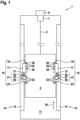
- Fig. 1 and 2 show differently designed elevator systems 1 with a braking device 15 according to two embodiments of the present invention.
- a concrete embodiment of the braking device 15 is shown larger and with more details.
- the elevator system 1 shown comprises an elevator car 3, which can be held by, for example, rope-like or belt-like support means 5 and displaced in an elevator shaft 11.
- the support means 5 can be displaced by a drive device 7.
- the drive device 7 is driven by a Control 9.
- the elevator car 3 is guided on both sides along at least one guide rail 13 serving as a stationary component 14.
- the elevator car 3 in order to keep the elevator car 3 stationary during a stop at a desired position, such as at a floor, the elevator car 3, after being moved to the desired position by the drive device 7, can be temporarily fixed to the stationary guide rails 13 by means of brakes 17 provided on its braking devices 15.
- Each of the brakes 17 is attached, for example, to a frame of the elevator car 3 by means of brake holding assemblies 19.
- At least one of the braking devices 15 further comprises a load measuring device 21.
- the load measuring device 21 comprises a force transmission element 25 and a counter element 29. Between the force transmission element 25 and the counter element 29, the load measuring device 21 may comprise a sensor, for example in the form of a strain gauge 27, by means of which a force acting on the load measuring device 21 between its force transmission element 25 and its counter element 29 can be measured.
- the load measuring device 21 may, for example, comprise evaluation electronics in its counter element 29, by means of which the measurement parameters prevailing at the sensor can be converted into electrical signals.
- the load measuring device 21 is also attached to the elevator car 3 via a load measuring device holding arrangement 23.
- Fig. 2 shows a further embodiment of an elevator installation 1 according to the invention.
- the braking device 15 is shown only schematically in this case and can be designed in a similar way to the one shown in Fig. 1 illustrated embodiment.
- the elevator installation 1 has an elevator car 3 and two counterweights 8.
- the elevator installation 1 comprises two drive devices 7, which are arranged in a shaft pit 10 of an elevator shaft 11.
- the traction and suspension are separate, i.e., two traction support means 4 (below the car) and two suspension support means 6 (above the car) are used.
- a braking device 15, as described above and below, proves to be particularly advantageous when used in such an elevator installation 1, since braking on the drive devices 7, i.e. via traction support means 4, which are not tensioned by the weight of the elevator car 3, can be avoided.
- the two drive devices are arranged at the top of the shaft head 12 of the elevator shaft 11 (not shown).
- the load measurement may be present only on one braking device 15.
- the load measuring device holding arrangement 23 and the brake holding arrangement 19 are mechanically connected to one another via a web arrangement 31.
- a plurality of elongated holes 35 are formed in the brake holding arrangement 19.
- a longitudinal direction of the elongated holes 35 is essentially parallel to a force direction 39 in which a force caused by the brake 17 is directed.
- the direction of force 39 essentially corresponds to the direction of movement of the elevator car 3 and is thus essentially vertical.
- the length of the elongated holes 35 can, for example, be approximately 0.5 mm greater than their width.
- the plurality of elongated holes 35 are arranged linearly one above the other along the direction of force 39.
- a fixing element 36 for example in the form of a bolt or a screw, can extend through each of the elongated holes 35 and can be fixed to the elevator car 3 or its frame.
- the brake holding arrangement 19 can thus be held to the elevator car 3 via the fixing elements 36, but can be moved slightly vertically relative to the elevator car 3 by displacing the fixing elements 36 within the elongated holes 35.
- the load measuring device holding arrangement 23 has a plurality of round holes 33. Fixing elements (not shown) can in turn run through the round holes 33, via which the load measuring device holding arrangement 23 can be fastened to the elevator car 3 or to its frame essentially without play.
- the brake 17 held by the brake holding arrangement 19 can shift slightly along the force direction 39 relative to the load measuring device holding arrangement 23 or relative to the elevator car 3 when a force in the force direction 39 is caused by activating the brake 17.
- Such a relative displacement causes, among other things, a deformation of the web arrangement 31.
- the web arrangement 31 is arranged, dimensioned and configured in such a way that this deformation is generally elastic, at least as long as the brake 17 only causes forces that are required to hold the elevator car 3 and its payload, for example during a stop at a floor.
- the relative displacements between the brake 17 and the car 3 caused when the brake 17 is activated can also be used to measure loads or load changes currently acting on the elevator car 3 with the aid of the load measuring device 21.
- the counter element 29 of the load measuring device 21 is firmly connected, for example, screwed, to the load measuring device holding arrangement 23.
- the force transmission element 25 is coupled, for example, to a part of the brake holding arrangement 19 and thus effectively connected to the brake 17.
- electronics arranged, for example, in the counter element 29 (not shown)
- mechanical stresses such as those that arise in the strain gauge 27 arranged between the force transmission element 25 and the counter element 29 due to the forces caused by the relative displacement, can be measured.
- the electronics can then generate an electrical signal, which can serve as a measure of the force experienced by the load measuring device 21.
- the braking device 15 can thus not only be used with its brake 17 to brake the elevator car 3, but can also be used with its load measuring device 21 to measure a load acting on the elevator car 3.
- the elevator car 3 can be moved to a floor, for example, using the drive device 7.
- the brake 17 of the braking device 15 can be activated, for example, via a control line 37, before the car doors are opened.
- a force currently acting between the brake 17 and the elevator car 3 can be measured using the load measuring device 21.
- this force can be zero, for example, in particular in the event that the elevator car 3 was braked to a standstill exclusively by controlling the drive device 7 and the brake 17 was only activated afterwards.
- this force can also be non-zero. This previously measured force can be saved as a reference value.
- load changes occur during the subsequent boarding and disembarking of passengers in the cabin, these changes can be measured using the load measuring device 21.
- the information about the measured load changes can be used to vary the forces exerted on the elevator cabin 7 via the support means 5 by means of targeted control of the drive device 7 in such a way that the load changes that have occurred in the meantime are compensated.
- the drive device 7 can change the forces acting on the elevator car 3 via the support means 5 until the force currently measured by the load measuring device 21 again corresponds to the previously determined reference value.
Landscapes
- Engineering & Computer Science (AREA)
- Mechanical Engineering (AREA)
- Automation & Control Theory (AREA)
- Computer Networks & Wireless Communication (AREA)
- Maintenance And Inspection Apparatuses For Elevators (AREA)
- Elevator Control (AREA)
- Indicating And Signalling Devices For Elevators (AREA)
Claims (15)
- Dispositif de freinage (15) pour freiner une cabine d'ascenseur déplaçable (3) d'une installation d'ascenseur (1) et pour mesurer les variations de charge provoquées dans la cabine d'ascenseur (3), le dispositif de freinage (15) comprenant :un frein (17) pour freiner la cabine d'ascenseur (3) par rapport à un composant stationnaire (14) de l'installation d'ascenseur (1) ;un ensemble de maintien de frein (19) pour maintenir le frein (17) sur la cabine d'ascenseur (3) ;un dispositif de mesure de charge (21) avec un élément de transmission de force (25) pour mesurer une force agissant sur l'élément de transmission de force (25) ;un agencement de maintien de dispositif de mesure de charge (23) pour maintenir le dispositif de mesure de charge (21) sur la cabine d'ascenseur (3) ;le frein (17) et l'ensemble de retenue de frein (19) étant configurés de telle sorte que le frein (17) doit être retenu sur la cabine d'ascenseur (3) au moyen de l'ensemble de retenue de frein (19) de telle sorte que le frein (17) peut être déplacé par rapport à la cabine d'ascenseur (3) dans une direction de force (39) provoquée par le frein (17) ;dans lequel le dispositif de mesure de charge (21) et l'ensemble de support de dispositif de mesure de charge (23) sont configurés de telle sorte que le dispositif de mesure de charge (21) doit être supporté sur la cabine d'ascenseur (3) au moyen de l'ensemble de support de dispositif de mesure de charge (23) de telle sorte que le dispositif de mesure de charge (21) est fixé dans la direction de force (39) provoquée par le frein (17) par rapport à la cabine d'ascenseur (3) ;l'élément de transmission de force (25) du dispositif de mesure de charge (21) est relié fonctionnellement au frein (17) pour pouvoir mesurer une force agissant entre le frein (17) et le dispositif de mesure de charge (21) en raison d'un déplacement relatif du frein (17) par rapport au dispositif de mesure de charge (21) ; caractérisé en ce que l'ensemble de support de dispositif de mesure de charge (23) et l'ensemble de support de frein (19) sont reliés l'un à l'autre de manière élastiquement déformable par l'intermédiaire d'un ensemble de barre (31).
- Dispositif de freinage selon la revendication 1,
dans lequel le frein (17) et l'ensemble de retenue de frein (19) sont configurés de telle sorte que le frein (17) doit être retenu sur la cabine d'ascenseur (3) au moyen de l'ensemble de retenue de frein (19) de telle sorte que le frein (17) peut être déplacé au maximum jusqu'à une position prédéterminée dans la direction de force (39) provoquée par le frein (17) par rapport à la cabine d'ascenseur (3). - Dispositif de freinage selon l'une quelconque des revendications précédentes, dans lequel l'ensemble de maintien de frein (19) présente des trous oblongs (35) dont la direction longitudinale s'étend parallèlement à la direction de force (39) exercée par le frein (17) et à travers lesquels peuvent s'étendre des éléments de fixation (36) maintenus fixes sur la cabine d'ascenseur (3) afin de maintenir l'ensemble de maintien de frein (19) sur la cabine d'ascenseur (3).
- Dispositif de freinage selon l'une quelconque des revendications précédentes, dans lequel l'ensemble de barrettes (31) est agencé, dimensionné et configuré de telle sorte que l'ensemble de barrettes (31) se déforme sensiblement exclusivement de manière élastique sous l'effet d'une force transmise entre l'ensemble de retenue de frein (19) et l'ensemble de retenue de dispositif de mesure de charge (23), laquelle force correspond à un poids de la cabine d'ascenseur (3), y compris une charge utile maximale admissible de la cabine d'ascenseur (3).
- Dispositif de freinage selon l'une quelconque des revendications précédentes, dans lequel l'ensemble de barrettes (31) est agencé, dimensionné et configuré de telle sorte que l'ensemble de barrettes (31) se déforme de moins de 1 mm dans la direction de la force (39) exercée par le frein (17), sous l'effet d'une force transmise entre l'ensemble de retenue de frein (19) et l'ensemble de retenue de dispositif de mesure de charge (23), qui correspond à une force de poids de la cabine d'ascenseur (3), y compris une charge utile maximale admissible de la cabine d'ascenseur (3).
- Dispositif de freinage selon l'une des revendications précédentes, dans lequel l'ensemble de barrettes (31) s'étend, au moins dans une zone partielle, transversalement à la direction d'effort (39) exercée par le frein (17).
- Dispositif de freinage selon l'une quelconque des revendications précédentes, dans lequel l'ensemble de retenue de frein (19), l'ensemble de retenue de dispositif de mesure de charge (23) et l'ensemble de barrette (31) sont formés d'un seul tenant avec un composant commun.
- Dispositif de freinage selon la revendication 7, dans lequel l'ensemble de retenue de frein (19), l'ensemble de retenue de dispositif de mesure de charge (23) et l'ensemble de barre (31) sont formés d'un seul tenant avec une pièce de tôle commune estampée.
- Dispositif de freinage selon l'une quelconque des revendications précédentes, dans lequel l'élément de transmission de force (25) est relié à un élément complémentaire (29) du dispositif de mesure de charge (21) fixé à l'ensemble de maintien du dispositif de mesure de charge (23) par l'intermédiaire d'une jauge de contrainte (27).
- Dispositif de freinage selon l'une quelconque des revendications précédentes, dans lequel le dispositif de mesure de charge (21) est configuré pour générer un signal électrique représentatif de la force exercée sur l'élément de transmission de force (25).
- Dispositif de freinage selon l'une des revendications précédentes, dans lequel le frein (17) est configuré en tant que frein d'arrêt pour maintenir la cabine d'ascenseur (3) stationnaire contre son poids pendant un arrêt, et
le frein (17) étant de préférence configuré de manière complémentaire également comme frein d'arrêt pour freiner en urgence la cabine d'ascenseur (3) en cas de chute libre. - Installation d'ascenseur (1) comprenant :une cabine d'ascenseur (3) ;un rail de guidage (13) ; etun dispositif de freinage (15) selon l'une quelconque des revendications 1 à 11 ;la cabine d'ascenseur (3) étant déplaçable le long du rail de guidage (13) ;le dispositif de freinage (15) étant maintenu sur la cabine d'ascenseur (3) au moyen de son agencement de maintien de frein (19) et de son agencement de maintien de dispositif de mesure de charge (23) ; etdans lequel le frein (17) du dispositif de freinage (15) est configuré pour coopérer avec le rail de guidage (13) afin de freiner la cabine d'ascenseur (3).
- Procédé de mesure d'une charge agissant sur une cabine d'ascenseur (3), le procédé comprenant :l'activation du frein (17) d'un dispositif de freinage (15) maintenu sur la cabine d'ascenseur (3) selon l'une des revendications 1 à 11 pendant que la cabine d'ascenseur (3) est à l'arrêt ; etmesurer la charge agissant sur la cabine d'ascenseur (3) à l'aide du dispositif de mesure de charge (21) du dispositif de freinage (15).
- Procédé de réglage d'une force devant être exercée par un dispositif d'entraînement (7) sur une cabine d'ascenseur (3) en réponse à une variation de charge dans la cabine d'ascenseur (3), le procédé comprenant :mesurer la variation de charge à l'aide d'un procédé selon la revendication 13 ; etajuster la force exercée par le dispositif d'entraînement (7) sur la cabine d'ascenseur (3) de telle sorte que la variation de charge mesurée soit compensée.
- Procédé selon la revendication 14, dans lequel, avant l'apparition de la variation de charge, une force mesurée par le dispositif de mesure de charge (21) est mesurée en tant que force de référence ; et
dans lequel la force exercée sur la cabine d'ascenseur (3) après l'activation du frein (17) et après la modification de la charge dans la cabine d'ascenseur (3) est réglée de telle sorte qu'une force correspondant à la force de référence est mesurée par le dispositif de mesure de charge (21).
Applications Claiming Priority (2)
| Application Number | Priority Date | Filing Date | Title |
|---|---|---|---|
| EP19206540 | 2019-10-31 | ||
| PCT/EP2020/080403 WO2021084012A1 (fr) | 2019-10-31 | 2020-10-29 | Dispositif de frein pour cabine d'ascenseur, comprenant un dispositif de mesure de charge intégré, son utilisation dans un système d'ascenseur, et procédé |
Publications (2)
| Publication Number | Publication Date |
|---|---|
| EP4051613A1 EP4051613A1 (fr) | 2022-09-07 |
| EP4051613B1 true EP4051613B1 (fr) | 2025-06-11 |
Family
ID=68424825
Family Applications (1)
| Application Number | Title | Priority Date | Filing Date |
|---|---|---|---|
| EP20796610.2A Active EP4051613B1 (fr) | 2019-10-31 | 2020-10-29 | Dispositif de freinage pour une cabine d'ascenseur pourvu de dispositif de mesure de charge intégré et son utilisation dans une installation d'ascenseur et procédé |
Country Status (8)
| Country | Link |
|---|---|
| US (1) | US11772933B2 (fr) |
| EP (1) | EP4051613B1 (fr) |
| JP (1) | JP7618666B2 (fr) |
| KR (1) | KR102946996B1 (fr) |
| CN (1) | CN114616202B (fr) |
| AU (1) | AU2020376295B2 (fr) |
| BR (1) | BR112022007765A2 (fr) |
| WO (1) | WO2021084012A1 (fr) |
Families Citing this family (9)
| Publication number | Priority date | Publication date | Assignee | Title |
|---|---|---|---|---|
| KR102946996B1 (ko) * | 2019-10-31 | 2026-04-01 | 인벤티오 아게 | 총합 부하 측정 디바이스를 포함하는 엘리베이터 카용 브레이크 디바이스, 엘리베이터 시스템에서의 그의 용도, 및 방법 |
| EP3819245B1 (fr) * | 2019-11-08 | 2025-05-21 | KONE Corporation | Ascenseur |
| EP4446269A3 (fr) * | 2019-11-12 | 2024-11-06 | KONE Corporation | Frein de stationnement d'ascenseur, procédé de fonctionnement d'un système d'ascenseur et système d'ascenseur |
| EP4197953A1 (fr) * | 2021-12-17 | 2023-06-21 | KONE Corporation | Frein de stationnement d'ascenseur, procédé de fonctionnement d'un frein de stationnement d'ascenseur et dispositif de commande d'un frein de stationnement d'ascenseur |
| EP4452809B1 (fr) | 2021-12-20 | 2026-02-04 | Inventio AG | Dispositif de mesure d'une force dans une installation d'ascenseur, procédé de vérification de l'équilibrage d'une installation d'ascenseur, ainsi qu'installation d'ascenseur permettant de mettre en oeuvre le procédé |
| CN118632814A (zh) | 2021-12-20 | 2024-09-10 | 因温特奥股份公司 | 用于测量电梯设备上的力的装置、用于测量电梯设备的可移动部件上的力的方法以及执行所述方法的电梯设备 |
| EP4452814B1 (fr) | 2021-12-23 | 2025-11-26 | Inventio Ag | Dispositif de freinage pour une cabine d'ascenseur et son utilisation dans une installation d'ascenseur et procédé |
| WO2025008297A1 (fr) * | 2023-07-04 | 2025-01-09 | Inventio Ag | Système d'ascenseur à charge lourde comprenant une pluralité de machines d'entraînement |
| WO2025172327A1 (fr) * | 2024-02-14 | 2025-08-21 | Inventio Ag | Dispositif de freinage et agencement de cabine pour un système d'ascenseur, et système d'ascenseur |
Citations (3)
| Publication number | Priority date | Publication date | Assignee | Title |
|---|---|---|---|---|
| JPH03216477A (ja) * | 1990-01-23 | 1991-09-24 | Mitsubishi Electric Corp | リニアモータ式エレベータの制御装置 |
| JPH07157212A (ja) * | 1993-12-06 | 1995-06-20 | Hitachi Ltd | リニアモータエレベータ |
| US6483047B1 (en) * | 2000-09-13 | 2002-11-19 | Otis Elevator Company | Elevator brake load weighing system |
Family Cites Families (20)
| Publication number | Priority date | Publication date | Assignee | Title |
|---|---|---|---|---|
| CH663949A5 (de) | 1984-02-14 | 1988-01-29 | Inventio Ag | Lastmesseinrichtung fuer eine aufzugskabine. |
| JPH0772060B2 (ja) * | 1985-09-03 | 1995-08-02 | 株式会社日立製作所 | エレベ−タ−の起動補償装置 |
| US5156239A (en) * | 1991-12-17 | 1992-10-20 | Otis Elevator Company | Disc brake/load weighing assembly for elevator drive sheave |
| JP2001019292A (ja) * | 1999-06-25 | 2001-01-23 | Inventio Ag | 鉛直搬送装置の荷重支持手段の鉛直方向変位と鉛直方向振動とを防止する装置および方法 |
| RU2271327C2 (ru) | 2000-05-01 | 2006-03-10 | Инвенцио Аг | Грузоподъемное приспособление для канатных лифтов со встроенным грузоизмерительным устройством |
| US6450299B1 (en) * | 2000-09-14 | 2002-09-17 | C.E. Electronics, Inc. | Load measuring for an elevator car |
| US7604099B2 (en) * | 2004-03-15 | 2009-10-20 | Mitsubishi Electric Corporation | Brake device for elevator |
| CA2543381C (fr) * | 2004-03-30 | 2009-06-23 | Mitsubishi Denki Kabushiki Kaisha | Dispositif de commande d'ascenseur |
| EP1826168B1 (fr) | 2004-12-15 | 2013-04-17 | Mitsubishi Electric Corporation | Dispositif d'arret d'urgence pour ascenseur |
| MY192706A (en) * | 2004-12-17 | 2022-09-02 | Inventio Ag | Lift installation with a braking device, and method for braking and holding a lift installation |
| FI120763B (fi) * | 2006-06-05 | 2010-02-26 | Kone Corp | Menetelmä kuorman mittaamiseksi hississä ja hissi |
| US7784589B2 (en) * | 2006-07-10 | 2010-08-31 | Inventio Ag | Elevator lift cage load measuring assembly |
| WO2009143450A2 (fr) * | 2008-05-23 | 2009-11-26 | Thyssenkrupp Elevator Capital Corporation | Système de guidage et d’équilibrage actif pour ascenseur |
| ES2614438T3 (es) * | 2009-03-16 | 2017-05-31 | Otis Elevator Company | Activador electromagnético de seguridad |
| US9856111B1 (en) * | 2009-04-24 | 2018-01-02 | Paul Anderson | Elevator structure and brake system therefor |
| ES2566063T3 (es) * | 2011-09-30 | 2016-04-08 | Inventio Ag | Dispositivo de freno con accionamiento electromecánico |
| JP6157924B2 (ja) | 2013-05-20 | 2017-07-05 | 株式会社日立製作所 | 安全装置付きエレベータ |
| DE102014213404A1 (de) * | 2014-07-10 | 2016-01-14 | Thyssenkrupp Ag | Aufzugsanlage mit Bremseinrichtung am Fahrkorb und Verfahren zum Betrieb der Selbigen |
| DE202018004562U1 (de) * | 2018-10-02 | 2018-10-16 | Matthias Schernikau Gmbh | Vorrichtung zur Fahrwegbegrenzung eines Fahrkorbs und/oder eines Gegengewichts einer Aufzugsanlage mit einer Führungsschiene |
| KR102946996B1 (ko) * | 2019-10-31 | 2026-04-01 | 인벤티오 아게 | 총합 부하 측정 디바이스를 포함하는 엘리베이터 카용 브레이크 디바이스, 엘리베이터 시스템에서의 그의 용도, 및 방법 |
-
2020
- 2020-10-29 KR KR1020227014116A patent/KR102946996B1/ko active Active
- 2020-10-29 AU AU2020376295A patent/AU2020376295B2/en active Active
- 2020-10-29 BR BR112022007765A patent/BR112022007765A2/pt unknown
- 2020-10-29 US US17/755,157 patent/US11772933B2/en active Active
- 2020-10-29 EP EP20796610.2A patent/EP4051613B1/fr active Active
- 2020-10-29 CN CN202080076633.4A patent/CN114616202B/zh active Active
- 2020-10-29 WO PCT/EP2020/080403 patent/WO2021084012A1/fr not_active Ceased
- 2020-10-29 JP JP2022525305A patent/JP7618666B2/ja active Active
Patent Citations (3)
| Publication number | Priority date | Publication date | Assignee | Title |
|---|---|---|---|---|
| JPH03216477A (ja) * | 1990-01-23 | 1991-09-24 | Mitsubishi Electric Corp | リニアモータ式エレベータの制御装置 |
| JPH07157212A (ja) * | 1993-12-06 | 1995-06-20 | Hitachi Ltd | リニアモータエレベータ |
| US6483047B1 (en) * | 2000-09-13 | 2002-11-19 | Otis Elevator Company | Elevator brake load weighing system |
Also Published As
| Publication number | Publication date |
|---|---|
| CN114616202B (zh) | 2023-09-29 |
| KR102946996B1 (ko) | 2026-04-01 |
| JP2022554006A (ja) | 2022-12-27 |
| AU2020376295A1 (en) | 2022-05-26 |
| CN114616202A (zh) | 2022-06-10 |
| KR20220084065A (ko) | 2022-06-21 |
| AU2020376295B2 (en) | 2024-03-07 |
| EP4051613A1 (fr) | 2022-09-07 |
| WO2021084012A1 (fr) | 2021-05-06 |
| JP7618666B2 (ja) | 2025-01-21 |
| US20220363515A1 (en) | 2022-11-17 |
| US11772933B2 (en) | 2023-10-03 |
| BR112022007765A2 (pt) | 2022-07-05 |
Similar Documents
| Publication | Publication Date | Title |
|---|---|---|
| EP4051613B1 (fr) | Dispositif de freinage pour une cabine d'ascenseur pourvu de dispositif de mesure de charge intégré et son utilisation dans une installation d'ascenseur et procédé | |
| EP1292524B1 (fr) | Parachute de freinage muni d'une adaptation de la force de freinage pour un ascenseur | |
| DE69203697T2 (de) | Doppelseitige Fangvorrichtung. | |
| EP2900586B1 (fr) | Élément de guidage pour un rail de guidage d'un escalier roulant ou d'un trottoir roulant | |
| DE3715098C2 (fr) | ||
| EP1067084A1 (fr) | Dispositif et méthode pour éviter les glissements et les oscillations verticales sur des appareils de prise de charge pour des installations de transport vertical | |
| EP1700811B1 (fr) | Ascenseur | |
| WO2012004268A1 (fr) | Surveillance des moyens de suspension dans une installation d'ascenseur | |
| EP3774630A1 (fr) | Procédé et dispositif servant à surveiller des propriétés d'un ensemble de moyens de support dans un système d'ascenseur | |
| EP3468908B1 (fr) | Dispositif de levage avec dispositif d'arrêt | |
| EP1840068A1 (fr) | Ascenseur comprenant und dispositif de frein de cabine d'ascenseur et méthode de freinage d'une cabine d'ascenseur | |
| EP3215449B1 (fr) | Ascenseur équipé d'un dispositif de freinage | |
| EP4452814B1 (fr) | Dispositif de freinage pour une cabine d'ascenseur et son utilisation dans une installation d'ascenseur et procédé | |
| EP2582606B1 (fr) | Frein d'arrêt à dispositif de blocage | |
| EP1879825B1 (fr) | Dispositif de compensation d'allongement de cables d'ascenseurs | |
| EP4271640B1 (fr) | Dispositif de suspension et son utilisation dans une installation d'ascenseur et procédé | |
| WO2021148456A1 (fr) | Dispositif de levage servant à soulever par commande une charge utile à l'intérieur d'une gaine d'ascenseur | |
| WO2008011896A1 (fr) | Dispositif de freinage ou de blocage destiné à la sécurisation temporaire d'un espace de sécurité et similaires | |
| EP3831759A1 (fr) | Dispositif de guidage et de freinage d'un corps mobile d'une installation d'ascenseur à déplacer le long d'un rail de guidage | |
| EP3037375A1 (fr) | Installation d'ascenseur dotée d'un dispositif d'arrêt et de réglage pour un système de cabine d'ascenseur | |
| WO2019141726A1 (fr) | Ensemble bande de mesure destiné à être utilisé dans un ascenseur, permettant de déterminer une position absolue d'une cabine d'ascenseur le long d'un trajet de déplacement | |
| DE102025155152A1 (de) | Aufzugsanlage mit Hängekabel und Kompensationstragmittel | |
| WO2025172327A1 (fr) | Dispositif de freinage et agencement de cabine pour un système d'ascenseur, et système d'ascenseur | |
| EP3720799B1 (fr) | Dispositif d'arrêt pour cabine d'ascenseur, système d'ascenseur muni d'un dispositif d'arrêt et procédé de déverrouillage d'un dispositif d'arrêt | |
| EP1547956B1 (fr) | Dispositif et méthode pour la réduction des vibrations d'un cage d'ascenseur |
Legal Events
| Date | Code | Title | Description |
|---|---|---|---|
| STAA | Information on the status of an ep patent application or granted ep patent |
Free format text: STATUS: UNKNOWN |
|
| STAA | Information on the status of an ep patent application or granted ep patent |
Free format text: STATUS: THE INTERNATIONAL PUBLICATION HAS BEEN MADE |
|
| PUAI | Public reference made under article 153(3) epc to a published international application that has entered the european phase |
Free format text: ORIGINAL CODE: 0009012 |
|
| STAA | Information on the status of an ep patent application or granted ep patent |
Free format text: STATUS: REQUEST FOR EXAMINATION WAS MADE |
|
| 17P | Request for examination filed |
Effective date: 20220331 |
|
| AK | Designated contracting states |
Kind code of ref document: A1 Designated state(s): AL AT BE BG CH CY CZ DE DK EE ES FI FR GB GR HR HU IE IS IT LI LT LU LV MC MK MT NL NO PL PT RO RS SE SI SK SM TR |
|
| RAP3 | Party data changed (applicant data changed or rights of an application transferred) |
Owner name: INVENTIO AG |
|
| DAV | Request for validation of the european patent (deleted) | ||
| DAX | Request for extension of the european patent (deleted) | ||
| STAA | Information on the status of an ep patent application or granted ep patent |
Free format text: STATUS: EXAMINATION IS IN PROGRESS |
|
| 17Q | First examination report despatched |
Effective date: 20230602 |
|
| GRAP | Despatch of communication of intention to grant a patent |
Free format text: ORIGINAL CODE: EPIDOSNIGR1 |
|
| STAA | Information on the status of an ep patent application or granted ep patent |
Free format text: STATUS: GRANT OF PATENT IS INTENDED |
|
| GRAJ | Information related to disapproval of communication of intention to grant by the applicant or resumption of examination proceedings by the epo deleted |
Free format text: ORIGINAL CODE: EPIDOSDIGR1 |
|
| STAA | Information on the status of an ep patent application or granted ep patent |
Free format text: STATUS: EXAMINATION IS IN PROGRESS |
|
| INTG | Intention to grant announced |
Effective date: 20250131 |
|
| INTC | Intention to grant announced (deleted) | ||
| GRAP | Despatch of communication of intention to grant a patent |
Free format text: ORIGINAL CODE: EPIDOSNIGR1 |
|
| STAA | Information on the status of an ep patent application or granted ep patent |
Free format text: STATUS: GRANT OF PATENT IS INTENDED |
|
| INTG | Intention to grant announced |
Effective date: 20250325 |
|
| GRAS | Grant fee paid |
Free format text: ORIGINAL CODE: EPIDOSNIGR3 |
|
| GRAA | (expected) grant |
Free format text: ORIGINAL CODE: 0009210 |
|
| STAA | Information on the status of an ep patent application or granted ep patent |
Free format text: STATUS: THE PATENT HAS BEEN GRANTED |
|
| AK | Designated contracting states |
Kind code of ref document: B1 Designated state(s): AL AT BE BG CH CY CZ DE DK EE ES FI FR GB GR HR HU IE IS IT LI LT LU LV MC MK MT NL NO PL PT RO RS SE SI SK SM TR |
|
| REG | Reference to a national code |
Ref country code: GB Ref legal event code: FG4D Free format text: NOT ENGLISH |
|
| REG | Reference to a national code |
Ref country code: CH Ref legal event code: EP |
|
| REG | Reference to a national code |
Ref country code: DE Ref legal event code: R096 Ref document number: 502020011212 Country of ref document: DE |
|
| REG | Reference to a national code |
Ref country code: IE Ref legal event code: FG4D Free format text: LANGUAGE OF EP DOCUMENT: GERMAN |
|
| REG | Reference to a national code |
Ref country code: NL Ref legal event code: FP |
|
| PG25 | Lapsed in a contracting state [announced via postgrant information from national office to epo] |
Ref country code: ES Free format text: LAPSE BECAUSE OF FAILURE TO SUBMIT A TRANSLATION OF THE DESCRIPTION OR TO PAY THE FEE WITHIN THE PRESCRIBED TIME-LIMIT Effective date: 20250611 Ref country code: FI Free format text: LAPSE BECAUSE OF FAILURE TO SUBMIT A TRANSLATION OF THE DESCRIPTION OR TO PAY THE FEE WITHIN THE PRESCRIBED TIME-LIMIT Effective date: 20250611 |
|
| REG | Reference to a national code |
Ref country code: LT Ref legal event code: MG9D |
|
| PG25 | Lapsed in a contracting state [announced via postgrant information from national office to epo] |
Ref country code: GR Free format text: LAPSE BECAUSE OF FAILURE TO SUBMIT A TRANSLATION OF THE DESCRIPTION OR TO PAY THE FEE WITHIN THE PRESCRIBED TIME-LIMIT Effective date: 20250912 Ref country code: NO Free format text: LAPSE BECAUSE OF FAILURE TO SUBMIT A TRANSLATION OF THE DESCRIPTION OR TO PAY THE FEE WITHIN THE PRESCRIBED TIME-LIMIT Effective date: 20250911 |
|
| PG25 | Lapsed in a contracting state [announced via postgrant information from national office to epo] |
Ref country code: BG Free format text: LAPSE BECAUSE OF FAILURE TO SUBMIT A TRANSLATION OF THE DESCRIPTION OR TO PAY THE FEE WITHIN THE PRESCRIBED TIME-LIMIT Effective date: 20250611 |
|
| PG25 | Lapsed in a contracting state [announced via postgrant information from national office to epo] |
Ref country code: HR Free format text: LAPSE BECAUSE OF FAILURE TO SUBMIT A TRANSLATION OF THE DESCRIPTION OR TO PAY THE FEE WITHIN THE PRESCRIBED TIME-LIMIT Effective date: 20250611 |
|
| PG25 | Lapsed in a contracting state [announced via postgrant information from national office to epo] |
Ref country code: RS Free format text: LAPSE BECAUSE OF FAILURE TO SUBMIT A TRANSLATION OF THE DESCRIPTION OR TO PAY THE FEE WITHIN THE PRESCRIBED TIME-LIMIT Effective date: 20250911 |
|
| PG25 | Lapsed in a contracting state [announced via postgrant information from national office to epo] |
Ref country code: LV Free format text: LAPSE BECAUSE OF FAILURE TO SUBMIT A TRANSLATION OF THE DESCRIPTION OR TO PAY THE FEE WITHIN THE PRESCRIBED TIME-LIMIT Effective date: 20250611 |
|
| REG | Reference to a national code |
Ref country code: CH Ref legal event code: U11 Free format text: ST27 STATUS EVENT CODE: U-0-0-U10-U11 (AS PROVIDED BY THE NATIONAL OFFICE) Effective date: 20251101 |
|
| PGFP | Annual fee paid to national office [announced via postgrant information from national office to epo] |
Ref country code: NL Payment date: 20251024 Year of fee payment: 6 |
|
| PG25 | Lapsed in a contracting state [announced via postgrant information from national office to epo] |
Ref country code: PT Free format text: LAPSE BECAUSE OF FAILURE TO SUBMIT A TRANSLATION OF THE DESCRIPTION OR TO PAY THE FEE WITHIN THE PRESCRIBED TIME-LIMIT Effective date: 20251013 |
|
| PG25 | Lapsed in a contracting state [announced via postgrant information from national office to epo] |
Ref country code: IS Free format text: LAPSE BECAUSE OF FAILURE TO SUBMIT A TRANSLATION OF THE DESCRIPTION OR TO PAY THE FEE WITHIN THE PRESCRIBED TIME-LIMIT Effective date: 20251011 |
|
| PGFP | Annual fee paid to national office [announced via postgrant information from national office to epo] |
Ref country code: DE Payment date: 20251028 Year of fee payment: 6 |
|
| PGFP | Annual fee paid to national office [announced via postgrant information from national office to epo] |
Ref country code: GB Payment date: 20251023 Year of fee payment: 6 |
|
| PG25 | Lapsed in a contracting state [announced via postgrant information from national office to epo] |
Ref country code: SM Free format text: LAPSE BECAUSE OF FAILURE TO SUBMIT A TRANSLATION OF THE DESCRIPTION OR TO PAY THE FEE WITHIN THE PRESCRIBED TIME-LIMIT Effective date: 20250611 |
|
| PGFP | Annual fee paid to national office [announced via postgrant information from national office to epo] |
Ref country code: IT Payment date: 20251022 Year of fee payment: 6 |
|
| PGFP | Annual fee paid to national office [announced via postgrant information from national office to epo] |
Ref country code: FR Payment date: 20251027 Year of fee payment: 6 |
|
| PGFP | Annual fee paid to national office [announced via postgrant information from national office to epo] |
Ref country code: CH Payment date: 20251101 Year of fee payment: 6 |
|
| PG25 | Lapsed in a contracting state [announced via postgrant information from national office to epo] |
Ref country code: CZ Free format text: LAPSE BECAUSE OF FAILURE TO SUBMIT A TRANSLATION OF THE DESCRIPTION OR TO PAY THE FEE WITHIN THE PRESCRIBED TIME-LIMIT Effective date: 20250611 |
|
| PG25 | Lapsed in a contracting state [announced via postgrant information from national office to epo] |
Ref country code: PL Free format text: LAPSE BECAUSE OF FAILURE TO SUBMIT A TRANSLATION OF THE DESCRIPTION OR TO PAY THE FEE WITHIN THE PRESCRIBED TIME-LIMIT Effective date: 20250611 |
|
| PG25 | Lapsed in a contracting state [announced via postgrant information from national office to epo] |
Ref country code: EE Free format text: LAPSE BECAUSE OF FAILURE TO SUBMIT A TRANSLATION OF THE DESCRIPTION OR TO PAY THE FEE WITHIN THE PRESCRIBED TIME-LIMIT Effective date: 20250611 |
|
| PG25 | Lapsed in a contracting state [announced via postgrant information from national office to epo] |
Ref country code: SK Free format text: LAPSE BECAUSE OF FAILURE TO SUBMIT A TRANSLATION OF THE DESCRIPTION OR TO PAY THE FEE WITHIN THE PRESCRIBED TIME-LIMIT Effective date: 20250611 |
|
| PG25 | Lapsed in a contracting state [announced via postgrant information from national office to epo] |
Ref country code: RO Free format text: LAPSE BECAUSE OF FAILURE TO SUBMIT A TRANSLATION OF THE DESCRIPTION OR TO PAY THE FEE WITHIN THE PRESCRIBED TIME-LIMIT Effective date: 20250611 |
|
| PG25 | Lapsed in a contracting state [announced via postgrant information from national office to epo] |
Ref country code: DK Free format text: LAPSE BECAUSE OF FAILURE TO SUBMIT A TRANSLATION OF THE DESCRIPTION OR TO PAY THE FEE WITHIN THE PRESCRIBED TIME-LIMIT Effective date: 20250611 |
|
| PLBE | No opposition filed within time limit |
Free format text: ORIGINAL CODE: 0009261 |
|
| STAA | Information on the status of an ep patent application or granted ep patent |
Free format text: STATUS: NO OPPOSITION FILED WITHIN TIME LIMIT |
|
| REG | Reference to a national code |
Ref country code: CH Ref legal event code: L10 Free format text: ST27 STATUS EVENT CODE: U-0-0-L10-L00 (AS PROVIDED BY THE NATIONAL OFFICE) Effective date: 20260423 |