EP4053360B1 - Procédé de construction d'une tour pour une éolienne - Google Patents
Procédé de construction d'une tour pour une éolienne Download PDFInfo
- Publication number
- EP4053360B1 EP4053360B1 EP21160711.4A EP21160711A EP4053360B1 EP 4053360 B1 EP4053360 B1 EP 4053360B1 EP 21160711 A EP21160711 A EP 21160711A EP 4053360 B1 EP4053360 B1 EP 4053360B1
- Authority
- EP
- European Patent Office
- Prior art keywords
- sections
- tower
- section
- manufacturing
- production
- Prior art date
- Legal status (The legal status is an assumption and is not a legal conclusion. Google has not performed a legal analysis and makes no representation as to the accuracy of the status listed.)
- Active
Links
Images




Classifications
-
- E—FIXED CONSTRUCTIONS
- E04—BUILDING
- E04H—BUILDINGS OR LIKE STRUCTURES FOR PARTICULAR PURPOSES; SWIMMING OR SPLASH BATHS OR POOLS; MASTS; FENCING; TENTS OR CANOPIES, IN GENERAL
- E04H12/00—Towers; Masts or poles; Chimney stacks; Water-towers; Methods of erecting such structures
- E04H12/02—Structures made of specified materials
- E04H12/12—Structures made of specified materials of concrete or other stone-like material, with or without internal or external reinforcements, e.g. with metal coverings, with permanent form elements
-
- B—PERFORMING OPERATIONS; TRANSPORTING
- B33—ADDITIVE MANUFACTURING TECHNOLOGY
- B33Y—ADDITIVE MANUFACTURING, i.e. MANUFACTURING OF THREE-DIMENSIONAL [3D] OBJECTS BY ADDITIVE DEPOSITION, ADDITIVE AGGLOMERATION OR ADDITIVE LAYERING, e.g. BY 3D PRINTING, STEREOLITHOGRAPHY OR SELECTIVE LASER SINTERING
- B33Y40/00—Auxiliary operations or equipment, e.g. for material handling
-
- B—PERFORMING OPERATIONS; TRANSPORTING
- B33—ADDITIVE MANUFACTURING TECHNOLOGY
- B33Y—ADDITIVE MANUFACTURING, i.e. MANUFACTURING OF THREE-DIMENSIONAL [3D] OBJECTS BY ADDITIVE DEPOSITION, ADDITIVE AGGLOMERATION OR ADDITIVE LAYERING, e.g. BY 3D PRINTING, STEREOLITHOGRAPHY OR SELECTIVE LASER SINTERING
- B33Y40/00—Auxiliary operations or equipment, e.g. for material handling
- B33Y40/20—Post-treatment, e.g. curing, coating or polishing
-
- B—PERFORMING OPERATIONS; TRANSPORTING
- B33—ADDITIVE MANUFACTURING TECHNOLOGY
- B33Y—ADDITIVE MANUFACTURING, i.e. MANUFACTURING OF THREE-DIMENSIONAL [3D] OBJECTS BY ADDITIVE DEPOSITION, ADDITIVE AGGLOMERATION OR ADDITIVE LAYERING, e.g. BY 3D PRINTING, STEREOLITHOGRAPHY OR SELECTIVE LASER SINTERING
- B33Y80/00—Products made by additive manufacturing
-
- E—FIXED CONSTRUCTIONS
- E04—BUILDING
- E04H—BUILDINGS OR LIKE STRUCTURES FOR PARTICULAR PURPOSES; SWIMMING OR SPLASH BATHS OR POOLS; MASTS; FENCING; TENTS OR CANOPIES, IN GENERAL
- E04H12/00—Towers; Masts or poles; Chimney stacks; Water-towers; Methods of erecting such structures
- E04H12/34—Arrangements for erecting or lowering towers, masts, poles, chimney stacks, or the like
- E04H12/341—Arrangements for casting in situ concrete towers or the like
-
- E—FIXED CONSTRUCTIONS
- E04—BUILDING
- E04H—BUILDINGS OR LIKE STRUCTURES FOR PARTICULAR PURPOSES; SWIMMING OR SPLASH BATHS OR POOLS; MASTS; FENCING; TENTS OR CANOPIES, IN GENERAL
- E04H12/00—Towers; Masts or poles; Chimney stacks; Water-towers; Methods of erecting such structures
- E04H12/34—Arrangements for erecting or lowering towers, masts, poles, chimney stacks, or the like
- E04H12/342—Arrangements for stacking tower sections on top of each other
-
- F—MECHANICAL ENGINEERING; LIGHTING; HEATING; WEAPONS; BLASTING
- F03—MACHINES OR ENGINES FOR LIQUIDS; WIND, SPRING, OR WEIGHT MOTORS; PRODUCING MECHANICAL POWER OR A REACTIVE PROPULSIVE THRUST, NOT OTHERWISE PROVIDED FOR
- F03D—WIND MOTORS
- F03D13/00—Assembly, mounting or commissioning of wind motors; Arrangements specially adapted for transporting wind motor components
- F03D13/10—Assembly of wind motors; Arrangements for erecting wind motors
-
- F—MECHANICAL ENGINEERING; LIGHTING; HEATING; WEAPONS; BLASTING
- F03—MACHINES OR ENGINES FOR LIQUIDS; WIND, SPRING, OR WEIGHT MOTORS; PRODUCING MECHANICAL POWER OR A REACTIVE PROPULSIVE THRUST, NOT OTHERWISE PROVIDED FOR
- F03D—WIND MOTORS
- F03D13/00—Assembly, mounting or commissioning of wind motors; Arrangements specially adapted for transporting wind motor components
- F03D13/20—Arrangements for mounting or supporting wind motors; Masts or towers for wind motors
-
- F—MECHANICAL ENGINEERING; LIGHTING; HEATING; WEAPONS; BLASTING
- F05—INDEXING SCHEMES RELATING TO ENGINES OR PUMPS IN VARIOUS SUBCLASSES OF CLASSES F01-F04
- F05B—INDEXING SCHEME RELATING TO WIND, SPRING, WEIGHT, INERTIA OR LIKE MOTORS, TO MACHINES OR ENGINES FOR LIQUIDS COVERED BY SUBCLASSES F03B, F03D AND F03G
- F05B2230/00—Manufacture
- F05B2230/30—Manufacture with deposition of material
- F05B2230/31—Layer deposition
-
- Y—GENERAL TAGGING OF NEW TECHNOLOGICAL DEVELOPMENTS; GENERAL TAGGING OF CROSS-SECTIONAL TECHNOLOGIES SPANNING OVER SEVERAL SECTIONS OF THE IPC; TECHNICAL SUBJECTS COVERED BY FORMER USPC CROSS-REFERENCE ART COLLECTIONS [XRACs] AND DIGESTS
- Y02—TECHNOLOGIES OR APPLICATIONS FOR MITIGATION OR ADAPTATION AGAINST CLIMATE CHANGE
- Y02E—REDUCTION OF GREENHOUSE GAS [GHG] EMISSIONS, RELATED TO ENERGY GENERATION, TRANSMISSION OR DISTRIBUTION
- Y02E10/00—Energy generation through renewable energy sources
- Y02E10/70—Wind energy
- Y02E10/72—Wind turbines with rotation axis in wind direction
-
- Y—GENERAL TAGGING OF NEW TECHNOLOGICAL DEVELOPMENTS; GENERAL TAGGING OF CROSS-SECTIONAL TECHNOLOGIES SPANNING OVER SEVERAL SECTIONS OF THE IPC; TECHNICAL SUBJECTS COVERED BY FORMER USPC CROSS-REFERENCE ART COLLECTIONS [XRACs] AND DIGESTS
- Y02—TECHNOLOGIES OR APPLICATIONS FOR MITIGATION OR ADAPTATION AGAINST CLIMATE CHANGE
- Y02E—REDUCTION OF GREENHOUSE GAS [GHG] EMISSIONS, RELATED TO ENERGY GENERATION, TRANSMISSION OR DISTRIBUTION
- Y02E10/00—Energy generation through renewable energy sources
- Y02E10/70—Wind energy
- Y02E10/728—Onshore wind turbines
Definitions
- the present invention relates to a method for erecting a tower for a wind turbine, which has a plurality of superimposed sections.
- a wind turbine consists of a tower built on a foundation.
- the tower supports a nacelle containing an electric generator driven by a rotor.
- a wind turbine tower has been discovered that has at least one tower section made of different materials.
- the tower section has a wall manufactured using an additive process, which a first material and a plurality of additively manufactured internal reinforcement structures. This may, for example, be a metal reinforcement embedded in an additively applied cement.
- a wind turbine tower has become known in which individually manufactured tower sections are telescopic and can be connected to each other.
- the invention is based on the object of providing a method for producing a tower for a wind turbine, which allows the erection of the tower for the wind turbine using simple means.
- the method according to the invention is used to erect a tower for a wind turbine.
- the tower consists of a plurality of stacked sections.
- the method according to the invention comprises the following method steps: At least two nested, ring-shaped sections of the tower are manufactured using an additive manufacturing process. Nested means that, starting from a center, an inner section represents the tower in a radial direction, and this in turn is supported by another
- the sections are manufactured as closed, monolithic sections and not assembled from multiple segments. Particularly with a very large section diameter, for example 10 meters or more, it is advantageous that no vertical joints are necessary between section segments, which can be very difficult to connect.
- a 3D printer in particular can be used for the additive manufacturing process.
- the suitable 3D printer does not have to be able to move freely in space; for example, to produce a ring-shaped section it is sufficient if the print head of the 3D printer can move concentrically to the center of the section.
- Various aggregates or additives, such as fibers, can be added to the concrete used.
- the manufactured tower sections are prepared at an erection site for the tower's construction. "Preparing” here also means that the tower sections can be assembled from the manufacturing sites directly or indirectly to form the tower, for example, using a lifting crane. According to the invention, the tower is erected from the prepared sections by stacking them one on top of the other. In an advantageous embodiment of the method, the outermost of several nested sections is picked up by the crane and placed on the foundation or on a section already standing there, and connected to it.
- One embodiment of the method according to the invention consists in producing and providing stacked sections of the tower at different production stations. This facilitates the production of the sections at the production stations, since two sections directly stacked in the tower are not provided as nested sections in one production station. Only every second, third, or nth section, depending on the number of production stations, comes from one of the manufacturing sites, so the distances between the nested sections at the manufacturing sites are larger. This significantly simplifies the spatial construction of the nested sections of the tower in the manufacturing sites.
- the manufacturing sites are located in the immediate vicinity of the erection site, i.e., the foundation on which the tower is built. Immediate proximity here means, for example, that the manufacturing sites and the foundation are accessible by a crane in such a way that the crane can lift the sections directly from the respective manufacturing site onto the foundation. This is particularly advantageous when the outermost sections have a very large diameter, as any additional transport is unnecessary.
- the manufacturing sites are located near, but not directly adjacent to, the erection site, and the sections are transported from the manufacturing sites to the staging sites.
- the staging sites are located directly adjacent to the erection site and can preferably be installed at the erection site using a crane.
- the manufacturing stations are enclosed for the duration of the manufacturing process.
- Enclosed manufacturing stations have the advantage that environmental influences such as rain or dirt can be kept away from the manufacture of the sections.
- the enclosure is designed with insulating elements, defined workshop conditions can be created.
- a conditioned atmosphere can This means controlling the temperature, air pressure, and/or humidity, as well as their temporal progression.
- controlled air circulation within the enclosure—that is, additional controlled air movement around and/or between the sections—to influence the curing behavior of the concrete and thus increase the placement rate.
- the controlled air movement can be generated using fans and/or fixed or movable guide vanes at suitable locations.
- the nested sections are manufactured concentrically. This means that the manufacturing process creates sections that share a common center point.
- the tapered elements are designed with a constant cone angle.
- the sections taper in such a way that the completed tower has an outer contour resembling a parabola or hyperbola.
- the tapered shape allows multiple sections to be positioned concentrically within one another at the manufacturing sites.
- a wall of the conical sections has a lower diameter which substantially corresponds to an upper diameter of another section or the wall has an upper diameter which corresponds to a lower diameter of another section essentially coincides.
- the respective other section is located in a different production location. This ensures that the walls of the sections alternately removed from the production locations match each other in terms of their diameters.
- the at least one section with the tapered shape has a wall thickness that increases from bottom to top.
- a section located lower in the tower i.e., closer to the foundation, can have a thinner wall thickness than a section located higher up, i.e., closer to the nacelle.
- On-site production makes it easier to construct very large section diameters, which structurally require a significantly thinner wall thickness.
- a greater wall thickness may be required to absorb the loads arising due to the necessarily smaller diameter required for the connection to the nacelle. If the individual section has a wall thickness that increases from bottom to top, this avoids sudden changes in wall thickness from one section to the next. Sudden changes in wall thickness lead to uneven stresses in the wall, which would have to be compensated for by additional measures, such as additional reinforcement.
- the sections in one of the manufacturing stations have the same height. This facilitates the additive manufacturing process for the sections at the manufacturing station.
- the device for additively manufacturing the sections i.e. the 3D printer, additionally has a tool for refining the surface of the sections, in particular for smoothing the surface of the Wall, so that after the end of production no uneven structures remain.
- the tool can, for example, be designed in the manner of one or more spatulas or squeegees, or as an oscillating or rotating tool, or a combination of these.
- the tool is preferably designed such that it processes the surface of the wall in an area in which the wall material has already partially hardened and is therefore more dimensionally stable than the freshly applied material layer.
- a tool can be provided for grinding, i.e., surface grinding or fine grinding, the end face of the section so that the joints between the sections can be created without mortar during construction. This tool is preferably only used when the end face of the section has already hardened sufficiently to allow grinding. Furthermore, additionally or alternatively, a tool can be provided for inserting additional components, such as attachment points for tower installations. All sections are preferably made of the same material, in particular the same concrete.
- the sections are produced sequentially, preferably starting with the production of the outer section in one production station.
- the production of two or more sections takes place simultaneously at at least one of the production stations.
- the sections are then produced simultaneously in increasingly higher levels.
- the device for additively producing the sections preferably has several print heads of essentially the same design.
- Figure 1 shows a foundation 10 for a wind turbine tower to be erected.
- a first crane 12 is provided next to the foundation 10, which can stack ring-shaped tower sections one above the other to form a tower, at least in the lower area of the tower.
- To the side of the foundation 10 are Two manufacturing stations 14, 16 are provided.
- Each of the manufacturing stations 14, 16 has a storage unit 18, 20, which are each connected to a conveyor unit 22, 24 and thus feed an additive manufacturing device 26.
- the additive manufacturing device 26 is described below with reference to the Figures 3 and 4 explained in more detail.
- the two production stations 14, 16 are each equipped with an enclosure, whereby the atmosphere within the enclosure can be influenced by an air conditioning unit 38, 39 with regard to temperature, air pressure, and humidity; their temporal progression can also be adjusted.
- a circulating fan 40 inside the enclosure supports even distribution.
- each section is ring-shaped, thus describing a 360° angle. Nested means that the section with the smallest diameter is located furthest inside, i.e. closest to the center, followed by a section with a larger diameter. As shown in Figure 1 As can be seen, four sections are stacked one inside the other in each of the two production stations 14 and 16. Each of the sections has a constant cone angle, with the upright section standing on its end with the larger diameter and tapering towards the top to a smaller diameter. The cone angle is constant across the height of the annular section.
- sections are alternately placed on top of each other from the production stations 14 and 16.
- the lower section A of the tower is produced in the production station 14.
- the following section which is placed on top of section A, i.e. section B, is produced in the other production station 16.
- the following section at the height C is then again produced in the Production station 14 of section A.
- the sequence of sections A, C, E and G is then obtained, from the outside to the inside, as shown in Figure 2 can be seen, while for manufacturing station 16 the sequence of sections is from outside to inside with B, D, F.
- the advantage of always leaving out one section in each of the manufacturing stations is that the distance between the sections during production is greater.
- each section has a height of 8 m. In this case, 8 sections could be manufactured in one manufacturing station 14 and the remaining 7 sections in the other manufacturing station 16.
- the diameter of the tower for the wind turbine is 12 m at the foundation and 4 m in the nacelle area, the diameter is reduced by approximately 530 mm from each section to the next. This means that the diameter of each section is 530 mm larger at its base than at its head.
- the distance between the nested sections would be only 200 mm to 300 mm, which might be too small for stripping devices and the like.
- the diameter of the inner section is then 1060 mm smaller than 530 mm, which leaves sufficient space for tools when machining the sections, even with a thicker wall.
- An enclosure is provided for each of the manufacturing stations 14 and 16.
- the enclosure serves two purposes: first, it protects the sections from harmful environmental influences during the manufacturing process. Second, the enclosure allows for a certain degree of conditioned atmosphere to be created within the enclosure, thus improving the conditions for additive manufacturing.
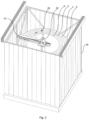
- Figure 2 shows an enclosure 28 in which the roof is shown transparent.
- the additive manufacturing process for sections A, C, E, and G takes place.
- Production takes place via the manufacturing device 26, which has a vertical mast 30 and a horizontal arm 32.
- the horizontal arm 32 moves in a circle around the mast 30.
- the height of the horizontal arm 32 on the mast is adjusted so that the arm 32 rises evenly with the increasing height of sections A to G.
- Figure 3 shows a schematic view of the entire structure of the production facility 26.
- the arm 32 can be adjusted in height in the direction of the double arrow h.
- a control system 34 controls the movements of arm 32.
- Arm 32 is connected to a flexible line 36 that runs from a reservoir 20 via a conveyor unit 22 to arm 32.
- the conveyor unit 22 is designed to convey liquid concrete from reservoir 20 via line 36 to arm 32, where the conveyed concrete exits to form the sections.
- the controller 34 may also control the conveyor station 22.
- Figure 4 shows another embodiment of the manufacturing facility.
- a double arm 42 is rotatably mounted on a crossbeam 44.
- the crossbeam 44 is carried by a support structure 46 and can be adjusted in height.
- On each side of the double arm 42 there are a number of work heads 48 for 3D printing, whereby the enlargement Z shows that these work heads 48 are also movable in the radial direction (double arrow i).
- On this side of the double arm 42 only one work head 48 is provided for every other section; further work heads 48 are provided on the other side of the double arm 42.
- the work heads 48 deliver the material for producing the sections and can also have tools for finishing the surface, for example for smoothing or grinding.
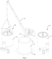
- Figure 5 shows a step in the erection of the tower from the manufactured sections.
- the enclosures of the manufacturing stations 14, 16 have been removed so that the sections can be picked up with the help of the crane 12 and placed on the foundation 10 or the sections already erected on it.
- Section A which was manufactured at the manufacturing station 14, is already standing on the foundation 10.
- Section B is attached to the crane 12 and is currently being lifted, with section B having been manufactured at the manufacturing station 16.
- section C is next. picked up again from production location 14 and placed on section B and so on.
- Figure 6 shows a cross-section of three sections 62, 64, 66 of a tower with a conical profile.
- Sections 62, 64, 66 each have a constant cone angle on the outer and inner contours, but the two cone angles are different, so that each section 62, 64, 66 has a greater wall thickness at its upper end than at its lower end.
- the diameters of sections 62, 64, 66 and their respective wall thicknesses are designed so that they fit together exactly.
- Figure 7 also shows a cross-section of three sections 72, 74, 76 of a tower with a parabolic profile.
- Sections 72, 74, 76 each extend with their outer and inner contours according to a segment of the parabola, such that each section 72, 74, 76 has a greater wall thickness at its upper end than at its lower end.
- the diameters and wall thicknesses are also designed such that sections 72, 74, 76 fit flush with one another without any overhang.
- Figure 8 shows schematically the course of the diameter or radius r and the wall thickness depending on the height h.
- Figure 8a shows a conical profile with sections 62, 64, 66 and
- Figure 8b shows a parabolic Profile with sections 72, 74, and 76. Shown are the inner sides 80, 82 and the outer sides 84, 86 of the tower wall and sections. The joints 88, 90 between the stacked sections are also shown. It is clearly visible that the wall thickness is greater in the upper section of the tower than in the lower section, and that the diameter decreases from bottom to top.
- the process according to the invention offers the possibility of manufacturing even large cement or concrete towers on-site without transport.
- the sections are manufactured on-site using a 3D printing process.
- the additive manufacturing process can also incorporate reinforcement structures or predetermined breaking points for openings into the tower section.
Landscapes
- Engineering & Computer Science (AREA)
- Architecture (AREA)
- Chemical & Material Sciences (AREA)
- Materials Engineering (AREA)
- Structural Engineering (AREA)
- Life Sciences & Earth Sciences (AREA)
- Civil Engineering (AREA)
- Manufacturing & Machinery (AREA)
- Sustainable Development (AREA)
- Sustainable Energy (AREA)
- Combustion & Propulsion (AREA)
- Mechanical Engineering (AREA)
- General Engineering & Computer Science (AREA)
- Wood Science & Technology (AREA)
- Wind Motors (AREA)
- Conveying And Assembling Of Building Elements In Situ (AREA)
Claims (13)
- Procédé de construction d'une tour pour une éolienne, dans lequel la tour présente une pluralité de sections placées les unes sur les autres, caractérisé en ce que le procédé présente les étapes suivantes :a. fabrication d'au moins deux sections de la tour placées les unes dans les autres à l'aide d'un procédé de fabrication additif, dans lequel la fabrication des sections de la tour est effectuée sur deux ou plusieurs sites de fabrication,b. mise à disposition des sections fabriquées de la tour sur un site de construction de la tour etc. construction de la tour sur le site de construction à partir des sections mises à disposition, en posant celles-ci les unes sur les autres, dans lequel des sections de différents sites de fabrications sont respectivement posées alternativement les unes sur les autres lors de la construction de la tour à partir des sections mises à disposition.
- Procédé selon la revendication 1, caractérisé en ce qu'une section située le plus à l'extérieur parmi la pluralité de sections placées les unes dans les autres est accueillie respectivement par une grue, soulevée et déposée sur le site de construction ou sur une section déjà placée sur celui-ci et reliée à celle-ci.
- Procédé selon la revendication 1 ou 2, caractérisé en ce que les sites de fabrication se situent à proximité immédiate du site de construction.
- Procédé selon l'une des revendications 1 à 3, caractérisé par le confinement de l'un au moins des sites de fabrication pour la durée de la fabrication des sections.
- Procédé selon la revendication 4, caractérisé en ce qu'une atmosphère conditionnée et/ou une convection d'air forcée règnent sur le site de fabrication confiné.
- Procédé selon l'une des revendications 1 à 5, caractérisé en ce que les sections sont fabriquées de manière à être placées concentriquement.
- Procédé selon l'une des revendications 1 à 6, caractérisé en ce que l'une au moins des sections présente une forme effilée de bas en haut.
- Procédé selon la revendication 7, caractérisé en ce qu'une paroi de l'au moins une section avec la forme effilée présente un diamètre inférieur coïncidant essentiellement avec le diamètre supérieur d'une autre section, et/ou présente un diamètre supérieur coïncidant essentiellement avec le diamètre inférieur d'une autre section.
- Procédé selon la revendication 7 ou 8, caractérisé en ce que l'au moins une section avec la forme effilée présente une épaisseur de paroi croissant de bas en haut.
- Procédé selon l'une des revendications 1 à 9, caractérisé en ce qu'un dispositif de fabrication additive des sections présente en outre un outil d'amélioration de la surface des sections.
- Procédé selon l'une des revendications 1 à 10, caractérisé en ce que la fabrication des sections sur l'un au moins des sites de fabrication est effectuée consécutivement, dans lequel la fabrication débute avec la section située le plus à l'extérieur.
- Procédé selon l'une des revendications 1 à 10, caractérisé en ce que la fabrication des sections est effectuée simultanément sur l'un au moins des sites de fabrication.
- Procédé selon la revendication 12, caractérisé en ce que le dispositif de fabrication additive des sections présente plusieurs têtes d'impression conçues de façon essentiellement identique.
Priority Applications (3)
| Application Number | Priority Date | Filing Date | Title |
|---|---|---|---|
| EP25177396.6A EP4578650A3 (fr) | 2021-03-04 | 2021-03-04 | Procédé de construction d'une tour pour une eolienne |
| EP21160711.4A EP4053360B1 (fr) | 2021-03-04 | 2021-03-04 | Procédé de construction d'une tour pour une éolienne |
| ES21160711T ES3035154T3 (en) | 2021-03-04 | 2021-03-04 | Method for creating a tower for a wind turbine |
Applications Claiming Priority (1)
| Application Number | Priority Date | Filing Date | Title |
|---|---|---|---|
| EP21160711.4A EP4053360B1 (fr) | 2021-03-04 | 2021-03-04 | Procédé de construction d'une tour pour une éolienne |
Related Child Applications (1)
| Application Number | Title | Priority Date | Filing Date |
|---|---|---|---|
| EP25177396.6A Division EP4578650A3 (fr) | 2021-03-04 | 2021-03-04 | Procédé de construction d'une tour pour une eolienne |
Publications (3)
| Publication Number | Publication Date |
|---|---|
| EP4053360A1 EP4053360A1 (fr) | 2022-09-07 |
| EP4053360C0 EP4053360C0 (fr) | 2025-05-21 |
| EP4053360B1 true EP4053360B1 (fr) | 2025-05-21 |
Family
ID=74858328
Family Applications (2)
| Application Number | Title | Priority Date | Filing Date |
|---|---|---|---|
| EP25177396.6A Pending EP4578650A3 (fr) | 2021-03-04 | 2021-03-04 | Procédé de construction d'une tour pour une eolienne |
| EP21160711.4A Active EP4053360B1 (fr) | 2021-03-04 | 2021-03-04 | Procédé de construction d'une tour pour une éolienne |
Family Applications Before (1)
| Application Number | Title | Priority Date | Filing Date |
|---|---|---|---|
| EP25177396.6A Pending EP4578650A3 (fr) | 2021-03-04 | 2021-03-04 | Procédé de construction d'une tour pour une eolienne |
Country Status (2)
| Country | Link |
|---|---|
| EP (2) | EP4578650A3 (fr) |
| ES (1) | ES3035154T3 (fr) |
Families Citing this family (5)
| Publication number | Priority date | Publication date | Assignee | Title |
|---|---|---|---|---|
| EP4343083A1 (fr) * | 2022-09-26 | 2024-03-27 | Nordex Energy Spain, S.A.U. | Segment en béton d'une section d'une tour d'éolienne, moule conçu pour couler un tel segment en béton et procédé d'assemblage d'une éolienne comprenant un tel segment en béton |
| US12529239B2 (en) | 2022-10-31 | 2026-01-20 | Ge Infrastructure Technology Llc | Wind turbine tower structure with stacked tower sections |
| WO2024260698A1 (fr) * | 2023-06-21 | 2024-12-26 | Nordex Energy Spain, S.A.U. | Segment de béton d'une section en béton supérieure d'une tour d'éolienne, moule configuré pour couler un tel segment de béton et procédé d'assemblage d'une éolienne comprenant un tel segment de béton |
| EP4731855A1 (fr) * | 2023-06-21 | 2026-04-29 | Nordex Energy Spain, S.A.U. | Segment en béton d'une section en béton supérieure d'une tour d'éolienne, moule conçu pour couler un tel segment en béton et procédé d'assemblage d'une éolienne comprenant un tel segment en béton |
| EP4495346A1 (fr) * | 2023-07-18 | 2025-01-22 | Guido Romanus Strohecker | Procédé de construction d'une construction et construction |
Family Cites Families (7)
| Publication number | Priority date | Publication date | Assignee | Title |
|---|---|---|---|---|
| DE102008016828A1 (de) * | 2008-04-01 | 2009-10-15 | Wobben, Aloys | Verfahren zur Herstellung von Betonfertigteilen |
| ES2396087B1 (es) * | 2011-06-30 | 2014-05-19 | Acciona Windpower, S.A. | Procedimiento de montaje de un aerogenerador y aerogenerador montado según dicho procedimiento |
| WO2013120889A1 (fr) | 2012-02-17 | 2013-08-22 | Siemens Aktiengesellschaft | Tour |
| ES2558025B1 (es) | 2014-07-30 | 2016-11-11 | Acciona Windpower, S.A. | Procedimiento de montaje de torres de hormigón de sección decreciente para aerogeneradores y aerogenerador asociado |
| US20190292803A1 (en) | 2018-03-26 | 2019-09-26 | General Electric Company | Additively manufactured tower structure and method of fabrication |
| WO2020068119A1 (fr) * | 2018-09-28 | 2020-04-02 | General Electric Company | Procédé de fabrication d'une structure de tour d'éolienne télescopique |
| CN113056606A (zh) * | 2018-09-28 | 2021-06-29 | 通用电气公司 | 用于制造风力涡轮塔架结构的系统和方法 |
-
2021
- 2021-03-04 EP EP25177396.6A patent/EP4578650A3/fr active Pending
- 2021-03-04 EP EP21160711.4A patent/EP4053360B1/fr active Active
- 2021-03-04 ES ES21160711T patent/ES3035154T3/es active Active
Also Published As
| Publication number | Publication date |
|---|---|
| EP4578650A2 (fr) | 2025-07-02 |
| EP4053360A1 (fr) | 2022-09-07 |
| EP4578650A3 (fr) | 2025-10-08 |
| ES3035154T3 (en) | 2025-08-29 |
| EP4053360C0 (fr) | 2025-05-21 |
Similar Documents
| Publication | Publication Date | Title |
|---|---|---|
| EP4053360B1 (fr) | Procédé de construction d'une tour pour une éolienne | |
| DE68912037T2 (de) | Baugerät und Bauverfahren. | |
| DE60309668T2 (de) | Windkraftanlage | |
| DE2823525C2 (de) | Windenergieanlage und Verfahren zu deren Errichten | |
| EP0674069B1 (fr) | Méthode et dispositif pour la réalisation de constructions avec l'emploi de briques de maçonnerie et/ou de coffrages | |
| DE102016205956A1 (de) | Selbstklettersystem, Selbstklettereinheit sowie Verfahren zum Umsetzen einer solchen Selbstklettereinheit an einem Betonbaukörper | |
| DE102008055607A1 (de) | Verfahren zum Errichten eines segmentierten Turms aus Spannbeton für Windkraftanlagen und Turm für Windkraftanlagen | |
| EP3464754B1 (fr) | Dispositif de montée pour la réalisation d'un mouvement par rapport à un mât et procédé de fabrication d'un mât | |
| DE102004032945A1 (de) | Einrichtung zur Herstellung und/oder Montage von Gütern | |
| WO2014005795A2 (fr) | Procédé de fabrication de cages d'armature destinées à des segments de tour, en particulier des segments de tour d'éolienne | |
| DE29908395U1 (de) | Vorrichtungen für einen Turmdrehkran als Obendreher mit Klettereinrichtung | |
| DE1284076B (de) | Verfahren zum Errichten eines Gebaeudes | |
| EP4495421A2 (fr) | Fondation pour une éolienne | |
| DE3146521A1 (de) | Verfahren und vorrichtung zum erstellen eines geschichteten behaelters an ort und stelle | |
| EP2712985B1 (fr) | Procédé de création d'une tour, notamment une tour d'éolienne | |
| EP3853472A1 (fr) | Segment de tour d'éolienne pour tour d'éolienne et procédé | |
| AT410343B (de) | Verfahren zur herstellung eines turmartigen bauwerks | |
| EP4419767B1 (fr) | Tour pour une éolienne ou une installation d'émission et de réception pour la téléphonie mobile | |
| CH637442A5 (de) | Kletterschalung zur herstellung einer geraden oder gekruemmten stahlbetonwand. | |
| DE3718436A1 (de) | Verfahren zur herstellung von turmartigen bauwerken | |
| EP3649305A1 (fr) | Procédé pour produire un coffrage à béton pour un segment de mât et procédé pour produire un segment de mât pour un mât d'une éolienne | |
| DE102012203883B4 (de) | Verfahren zur Errichtung eines Turms | |
| DE19936603A1 (de) | Verfahren zur Erstellung eines mast- oder turmartigen Hochbauwerkes sowie nach dem Verfahren herstellbares Hochbauwerk und bei der Verfahrensanwendung einsetzbare Innen- und/oder Außenschalung | |
| EP3805488A1 (fr) | Ensemble de moulage modulaire pour moules destiné au moulage des segments d'une paroi de tour d'une éolienne | |
| DE1285163B (de) | Verfahren zur Herstellung hoher Bauwerke und Vorrichtung zur Durchfuehrung dieses Verfahrens |
Legal Events
| Date | Code | Title | Description |
|---|---|---|---|
| PUAI | Public reference made under article 153(3) epc to a published international application that has entered the european phase |
Free format text: ORIGINAL CODE: 0009012 |
|
| STAA | Information on the status of an ep patent application or granted ep patent |
Free format text: STATUS: THE APPLICATION HAS BEEN PUBLISHED |
|
| AK | Designated contracting states |
Kind code of ref document: A1 Designated state(s): AL AT BE BG CH CY CZ DE DK EE ES FI FR GB GR HR HU IE IS IT LI LT LU LV MC MK MT NL NO PL PT RO RS SE SI SK SM TR |
|
| STAA | Information on the status of an ep patent application or granted ep patent |
Free format text: STATUS: REQUEST FOR EXAMINATION WAS MADE |
|
| 17P | Request for examination filed |
Effective date: 20230307 |
|
| RBV | Designated contracting states (corrected) |
Designated state(s): AL AT BE BG CH CY CZ DE DK EE ES FI FR GB GR HR HU IE IS IT LI LT LU LV MC MK MT NL NO PL PT RO RS SE SI SK SM TR |
|
| GRAP | Despatch of communication of intention to grant a patent |
Free format text: ORIGINAL CODE: EPIDOSNIGR1 |
|
| STAA | Information on the status of an ep patent application or granted ep patent |
Free format text: STATUS: GRANT OF PATENT IS INTENDED |
|
| RIC1 | Information provided on ipc code assigned before grant |
Ipc: B33Y 40/00 20200101ALI20241122BHEP Ipc: B33Y 40/20 20200101ALI20241122BHEP Ipc: E04H 12/34 20060101ALI20241122BHEP Ipc: F03D 13/10 20160101ALI20241122BHEP Ipc: F03D 13/20 20160101ALI20241122BHEP Ipc: B33Y 80/00 20150101ALI20241122BHEP Ipc: E04H 12/12 20060101AFI20241122BHEP |
|
| INTG | Intention to grant announced |
Effective date: 20241209 |
|
| GRAS | Grant fee paid |
Free format text: ORIGINAL CODE: EPIDOSNIGR3 |
|
| GRAA | (expected) grant |
Free format text: ORIGINAL CODE: 0009210 |
|
| STAA | Information on the status of an ep patent application or granted ep patent |
Free format text: STATUS: THE PATENT HAS BEEN GRANTED |
|
| AK | Designated contracting states |
Kind code of ref document: B1 Designated state(s): AL AT BE BG CH CY CZ DE DK EE ES FI FR GB GR HR HU IE IS IT LI LT LU LV MC MK MT NL NO PL PT RO RS SE SI SK SM TR |
|
| REG | Reference to a national code |
Ref country code: GB Ref legal event code: FG4D Free format text: NOT ENGLISH |
|
| REG | Reference to a national code |
Ref country code: CH Ref legal event code: EP |
|
| REG | Reference to a national code |
Ref country code: DE Ref legal event code: R096 Ref document number: 502021007501 Country of ref document: DE |
|
| REG | Reference to a national code |
Ref country code: IE Ref legal event code: FG4D Free format text: LANGUAGE OF EP DOCUMENT: GERMAN |
|
| U01 | Request for unitary effect filed |
Effective date: 20250603 |
|
| U07 | Unitary effect registered |
Designated state(s): AT BE BG DE DK EE FI FR IT LT LU LV MT NL PT RO SE SI Effective date: 20250611 |
|
| REG | Reference to a national code |
Ref country code: ES Ref legal event code: FG2A Ref document number: 3035154 Country of ref document: ES Kind code of ref document: T3 Effective date: 20250829 |
|
| PG25 | Lapsed in a contracting state [announced via postgrant information from national office to epo] |
Ref country code: GR Free format text: LAPSE BECAUSE OF FAILURE TO SUBMIT A TRANSLATION OF THE DESCRIPTION OR TO PAY THE FEE WITHIN THE PRESCRIBED TIME-LIMIT Effective date: 20250822 Ref country code: NO Free format text: LAPSE BECAUSE OF FAILURE TO SUBMIT A TRANSLATION OF THE DESCRIPTION OR TO PAY THE FEE WITHIN THE PRESCRIBED TIME-LIMIT Effective date: 20250821 |
|
| PG25 | Lapsed in a contracting state [announced via postgrant information from national office to epo] |
Ref country code: PL Free format text: LAPSE BECAUSE OF FAILURE TO SUBMIT A TRANSLATION OF THE DESCRIPTION OR TO PAY THE FEE WITHIN THE PRESCRIBED TIME-LIMIT Effective date: 20250521 |
|
| PG25 | Lapsed in a contracting state [announced via postgrant information from national office to epo] |
Ref country code: HR Free format text: LAPSE BECAUSE OF FAILURE TO SUBMIT A TRANSLATION OF THE DESCRIPTION OR TO PAY THE FEE WITHIN THE PRESCRIBED TIME-LIMIT Effective date: 20250521 |
|
| PG25 | Lapsed in a contracting state [announced via postgrant information from national office to epo] |
Ref country code: RS Free format text: LAPSE BECAUSE OF FAILURE TO SUBMIT A TRANSLATION OF THE DESCRIPTION OR TO PAY THE FEE WITHIN THE PRESCRIBED TIME-LIMIT Effective date: 20250821 |
|
| PG25 | Lapsed in a contracting state [announced via postgrant information from national office to epo] |
Ref country code: IS Free format text: LAPSE BECAUSE OF FAILURE TO SUBMIT A TRANSLATION OF THE DESCRIPTION OR TO PAY THE FEE WITHIN THE PRESCRIBED TIME-LIMIT Effective date: 20250921 |
|
| PG25 | Lapsed in a contracting state [announced via postgrant information from national office to epo] |
Ref country code: SM Free format text: LAPSE BECAUSE OF FAILURE TO SUBMIT A TRANSLATION OF THE DESCRIPTION OR TO PAY THE FEE WITHIN THE PRESCRIBED TIME-LIMIT Effective date: 20250521 |
|
| PG25 | Lapsed in a contracting state [announced via postgrant information from national office to epo] |
Ref country code: CZ Free format text: LAPSE BECAUSE OF FAILURE TO SUBMIT A TRANSLATION OF THE DESCRIPTION OR TO PAY THE FEE WITHIN THE PRESCRIBED TIME-LIMIT Effective date: 20250521 |
|
| PG25 | Lapsed in a contracting state [announced via postgrant information from national office to epo] |
Ref country code: SK Free format text: LAPSE BECAUSE OF FAILURE TO SUBMIT A TRANSLATION OF THE DESCRIPTION OR TO PAY THE FEE WITHIN THE PRESCRIBED TIME-LIMIT Effective date: 20250521 |
|
| PLBE | No opposition filed within time limit |
Free format text: ORIGINAL CODE: 0009261 |
|
| STAA | Information on the status of an ep patent application or granted ep patent |
Free format text: STATUS: NO OPPOSITION FILED WITHIN TIME LIMIT |
|
| REG | Reference to a national code |
Ref country code: CH Ref legal event code: L10 Free format text: ST27 STATUS EVENT CODE: U-0-0-L10-L00 (AS PROVIDED BY THE NATIONAL OFFICE) Effective date: 20260402 |
|
| 26N | No opposition filed |
Effective date: 20260224 |