EP4073444B1 - Couvercle multicouche d'un dispositif de tiroir à vide - Google Patents
Couvercle multicouche d'un dispositif de tiroir à vide Download PDFInfo
- Publication number
- EP4073444B1 EP4073444B1 EP20820909.8A EP20820909A EP4073444B1 EP 4073444 B1 EP4073444 B1 EP 4073444B1 EP 20820909 A EP20820909 A EP 20820909A EP 4073444 B1 EP4073444 B1 EP 4073444B1
- Authority
- EP
- European Patent Office
- Prior art keywords
- lid
- drawer
- circuit board
- printed circuit
- layer
- Prior art date
- Legal status (The legal status is an assumption and is not a legal conclusion. Google has not performed a legal analysis and makes no representation as to the accuracy of the status listed.)
- Active
Links
Images




Classifications
-
- F—MECHANICAL ENGINEERING; LIGHTING; HEATING; WEAPONS; BLASTING
- F25—REFRIGERATION OR COOLING; COMBINED HEATING AND REFRIGERATION SYSTEMS; HEAT PUMP SYSTEMS; MANUFACTURE OR STORAGE OF ICE; LIQUEFACTION SOLIDIFICATION OF GASES
- F25D—REFRIGERATORS; COLD ROOMS; ICE-BOXES; COOLING OR FREEZING APPARATUS NOT OTHERWISE PROVIDED FOR
- F25D25/00—Charging, supporting, and discharging the articles to be cooled
- F25D25/02—Charging, supporting, and discharging the articles to be cooled by shelves
- F25D25/024—Slidable shelves
- F25D25/025—Drawers
-
- B—PERFORMING OPERATIONS; TRANSPORTING
- B65—CONVEYING; PACKING; STORING; HANDLING THIN OR FILAMENTARY MATERIAL
- B65D—CONTAINERS FOR STORAGE OR TRANSPORT OF ARTICLES OR MATERIALS, e.g. BAGS, BARRELS, BOTTLES, BOXES, CANS, CARTONS, CRATES, DRUMS, JARS, TANKS, HOPPERS, FORWARDING CONTAINERS; ACCESSORIES, CLOSURES, OR FITTINGS THEREFOR; PACKAGING ELEMENTS; PACKAGES
- B65D81/00—Containers, packaging elements, or packages, for contents presenting particular transport or storage problems, or adapted to be used for non-packaging purposes after removal of contents
- B65D81/18—Containers, packaging elements, or packages, for contents presenting particular transport or storage problems, or adapted to be used for non-packaging purposes after removal of contents providing specific environment for contents, e.g. temperature above or below ambient
- B65D81/20—Containers, packaging elements, or packages, for contents presenting particular transport or storage problems, or adapted to be used for non-packaging purposes after removal of contents providing specific environment for contents, e.g. temperature above or below ambient under vacuum or superatmospheric pressure, or in a special atmosphere, e.g. of inert gas
- B65D81/2007—Containers, packaging elements, or packages, for contents presenting particular transport or storage problems, or adapted to be used for non-packaging purposes after removal of contents providing specific environment for contents, e.g. temperature above or below ambient under vacuum or superatmospheric pressure, or in a special atmosphere, e.g. of inert gas under vacuum
-
- A—HUMAN NECESSITIES
- A47—FURNITURE; DOMESTIC ARTICLES OR APPLIANCES; COFFEE MILLS; SPICE MILLS; SUCTION CLEANERS IN GENERAL
- A47B—TABLES; DESKS; OFFICE FURNITURE; CABINETS; DRAWERS; GENERAL DETAILS OF FURNITURE
- A47B77/00—Kitchen cabinets
- A47B77/04—Provision for particular uses of compartments or other parts ; Compartments moving up and down, revolving parts
- A47B77/16—Provision for particular uses of compartments or other parts ; Compartments moving up and down, revolving parts by adaptation of compartments or drawers for receiving or holding foodstuffs; by provision of rotatable or extensible containers for foodstuffs
-
- A—HUMAN NECESSITIES
- A47—FURNITURE; DOMESTIC ARTICLES OR APPLIANCES; COFFEE MILLS; SPICE MILLS; SUCTION CLEANERS IN GENERAL
- A47B—TABLES; DESKS; OFFICE FURNITURE; CABINETS; DRAWERS; GENERAL DETAILS OF FURNITURE
- A47B88/00—Drawers for tables, cabinets or like furniture; Guides for drawers
- A47B88/90—Constructional details of drawers
- A47B88/919—Accessories or additional elements for drawers, e.g. drawer lighting
-
- B—PERFORMING OPERATIONS; TRANSPORTING
- B65—CONVEYING; PACKING; STORING; HANDLING THIN OR FILAMENTARY MATERIAL
- B65D—CONTAINERS FOR STORAGE OR TRANSPORT OF ARTICLES OR MATERIALS, e.g. BAGS, BARRELS, BOTTLES, BOXES, CANS, CARTONS, CRATES, DRUMS, JARS, TANKS, HOPPERS, FORWARDING CONTAINERS; ACCESSORIES, CLOSURES, OR FITTINGS THEREFOR; PACKAGING ELEMENTS; PACKAGES
- B65D81/00—Containers, packaging elements, or packages, for contents presenting particular transport or storage problems, or adapted to be used for non-packaging purposes after removal of contents
- B65D81/18—Containers, packaging elements, or packages, for contents presenting particular transport or storage problems, or adapted to be used for non-packaging purposes after removal of contents providing specific environment for contents, e.g. temperature above or below ambient
- B65D81/20—Containers, packaging elements, or packages, for contents presenting particular transport or storage problems, or adapted to be used for non-packaging purposes after removal of contents providing specific environment for contents, e.g. temperature above or below ambient under vacuum or superatmospheric pressure, or in a special atmosphere, e.g. of inert gas
- B65D81/2007—Containers, packaging elements, or packages, for contents presenting particular transport or storage problems, or adapted to be used for non-packaging purposes after removal of contents providing specific environment for contents, e.g. temperature above or below ambient under vacuum or superatmospheric pressure, or in a special atmosphere, e.g. of inert gas under vacuum
- B65D81/2038—Containers, packaging elements, or packages, for contents presenting particular transport or storage problems, or adapted to be used for non-packaging purposes after removal of contents providing specific environment for contents, e.g. temperature above or below ambient under vacuum or superatmospheric pressure, or in a special atmosphere, e.g. of inert gas under vacuum with means for establishing or improving vacuum
-
- A—HUMAN NECESSITIES
- A47—FURNITURE; DOMESTIC ARTICLES OR APPLIANCES; COFFEE MILLS; SPICE MILLS; SUCTION CLEANERS IN GENERAL
- A47B—TABLES; DESKS; OFFICE FURNITURE; CABINETS; DRAWERS; GENERAL DETAILS OF FURNITURE
- A47B2210/00—General construction of drawers, guides and guide devices
- A47B2210/08—Covers or lids for sliding drawers
-
- F—MECHANICAL ENGINEERING; LIGHTING; HEATING; WEAPONS; BLASTING
- F25—REFRIGERATION OR COOLING; COMBINED HEATING AND REFRIGERATION SYSTEMS; HEAT PUMP SYSTEMS; MANUFACTURE OR STORAGE OF ICE; LIQUEFACTION SOLIDIFICATION OF GASES
- F25D—REFRIGERATORS; COLD ROOMS; ICE-BOXES; COOLING OR FREEZING APPARATUS NOT OTHERWISE PROVIDED FOR
- F25D2317/00—Details or arrangements for circulating cooling fluids; Details or arrangements for circulating gas, e.g. air, within refrigerated spaces, not provided for in other groups of this subclass
- F25D2317/04—Treating air flowing to refrigeration compartments
- F25D2317/041—Treating air flowing to refrigeration compartments by purification
- F25D2317/0411—Treating air flowing to refrigeration compartments by purification by dehumidification
-
- F—MECHANICAL ENGINEERING; LIGHTING; HEATING; WEAPONS; BLASTING
- F25—REFRIGERATION OR COOLING; COMBINED HEATING AND REFRIGERATION SYSTEMS; HEAT PUMP SYSTEMS; MANUFACTURE OR STORAGE OF ICE; LIQUEFACTION SOLIDIFICATION OF GASES
- F25D—REFRIGERATORS; COLD ROOMS; ICE-BOXES; COOLING OR FREEZING APPARATUS NOT OTHERWISE PROVIDED FOR
- F25D2317/00—Details or arrangements for circulating cooling fluids; Details or arrangements for circulating gas, e.g. air, within refrigerated spaces, not provided for in other groups of this subclass
- F25D2317/04—Treating air flowing to refrigeration compartments
- F25D2317/043—Treating air flowing to refrigeration compartments by creating a vacuum in a storage compartment
Definitions
- the present invention describes a multi-layer sandwich-constructed lid for placement on a drawer of a vacuum drawer device, which lid enables evacuation of a drawer interior after sealing to the drawer, wherein the lid has at least one outer airtight cover layer and a core layer, wherein recesses are formed in the core layer and partially in one of the at least one outer cover layer, in which recesses an evacuation channel, a pump and at least one sensor are arranged.
- Refrigerators for storing food have several disadvantages, as they constantly require a lot of electrical energy to maintain constant, massive cooling.
- the internal climate of refrigerators has received little attention to date.
- the Hygiene Council which conducted an international study called the Hygiene Report 2010, refrigerators contain around 1,140,000 germs per square centimeter, which is more contaminated than a toilet, which has around 100 germs per square centimeter. This report received widespread media coverage in 2010, but other than recommendations to clean refrigerators more frequently, no noticeable improvements have been made so far.
- Vacuum drawer device For the first time in the DE202017006169 generally discloses a vacuum drawer device with a drawer and a lid, wherein a vacuum can be generated in the interior of the drawer by means of a pump.
- Vacuum drawer device comprises a drawer with walls and a drawer interior, wherein the drawer is operatively connectable to a lid and is mounted within a drawer body for linear movement. Further details about the drawer, the lid, possibly lifting means and evacuation means are in the DE202017006169 but largely left open.
- the closest state of the art is the WO2019/141574 of the applicant.
- Food that does not necessarily require refrigeration can be stored at room temperature in a vacuum drawer device, thereby avoiding increased energy consumption for cooling.
- the drawer interior is evacuated to a slight negative pressure, which is generated and maintained in a controlled manner. This makes it easier to keep food edible or enjoyable for longer.
- Storage in a drawer body with a vacuum drawer device requires less energy than a refrigerator, as the oxygen removal from the interior is completed after a few minutes and almost no further electricity is required thereafter.
- a vacuum drawer device can be implemented without harmful materials such as refrigerants or thermal insulation.
- the consumption of plastic bags in the conventional vacuum sealing using vacuum sealers can be significantly reduced, yet food can still be stored for longer periods without any problems.
- the drawer body forms the outer shell, within which the lid and drawer are movably and securely mounted. Electrically operated lifting and evacuation devices are located in the lid or drawer, allowing controlled evacuation when the lid is placed on the drawer. Air can be pumped out of the drawer interior through an air duct. With the installation of sensors, the evacuation can be automated, and ventilation before the drawer is opened can also be detected and automatically initiated by the control system.
- the lid is designed to be as compact as possible, with multiple layers, and can also be easily mounted on existing drawers. To keep the height of the lid low, the lifting and evacuation devices are integrated into the lid as much as possible. In practice, however, the lid is still relatively heavy and bulky, and constant operation of the lid, i.e., with opposing lifting movements, can lead to malfunctions.
- the lid 2 which is movable within the drawer body 9 and is designed to be airtight, serves to evacuate the drawer interior R.
- the lid 2 is mounted so that it can be lowered onto the drawer 3 in a lifting direction H perpendicular to the pushing direction S.
- the lid 2 is attached to the drawer body 9 with mounting brackets 19, so that a relative movement of the lid 2 to the drawer 3 is possible.
- Lifting means 7 are arranged on or in the lid 2 within the drawer body 9, which keep the lid 2 movable within the drawer body 9 in the lifting direction H.
- the design of the lifting means 7 can be carried out in different ways, which will not be discussed further here.
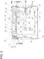
- FIG. 2 The airtight, multi-layered lid 2 is shown resting on the drawer 3 or sealing fittings 15.
- the surrounding drawer body 9 is omitted for simplicity, and the drawer 3 is shown in section with a front panel 17 and a handle 12.
- the lid 2 rests on the container interior R or the containers 14, hermetically sealing them.
- At least one evacuation channel should be arranged within the cover 2 in recesses A.
- recesses (A) are formed in a core layer (21') and partially in one of the at least one outer cover layers (22") of the cover (2), in which recesses an evacuation channel and/or a dehumidification channel, a pump and/or a fan and at least one sensor are arranged.
- Automated evacuation by means of a pump can be achieved through the at least one evacuation channel, and automated air exchange by means of a fan 81' of the drawer interior R or the interiors of the containers 14 can be achieved through the at least one air channel.
- the different paths of the air during evacuation and air exchange are indicated by dashed lines.
- a power cable 27' is arranged to a connector plug 25', which operates the control unit that controls the lifting means, the evacuation means, the air exchange means, and the sensors.
- the control unit is also arranged in a recess A in the lid 2, but could also be arranged within the drawer body 9, separate from the lid 2.
- the cover 2 is manufactured in a sandwich construction, with different materials being combined in different layers to form a cover 2.
- the cover 2 has two outer airtight cover layers 22', 22" and a core layer 21'.
- an additional printed circuit board 20' which can also be used instead of one of the outer airtight cover layers 22', 22".
- the layers 20', 21', 22', 22" are statically bonded together to form a multi-layer cover 2, which is designed to be correspondingly torsionally rigid.
- the upper cover layer 22' is airtight and can be made of MDF, CFRP, or glass.
- an air-impermeable plastic coating can also be arranged on an air-permeable material as the upper cover layer 22' in order to achieve the airtightness of the upper cover layer 22'.
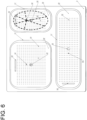
- Recesses A are provided in the core layer 21', in which the electrical devices, such as evacuation means, in particular the pump, air exchange means, in particular at least one fan 81', and sensors, in particular at least one humidity sensor 82', are arranged. Motors or other components of the lifting means can also be partially installed in the recesses A.
- At least one air duct which is necessary for the exhaust air of the fan 81', and at least one evacuation duct, which interacts with the pump and is necessary for generating a negative pressure or vacuum within the drawer interior R.
- All electrical components are mechanically mounted by means of a 20' printed circuit board and electrically connected to each other and to the control system.
- the core layer 21' can be made of a rigid plastic foam or a honeycomb plastic structure or a solid plastic layer, whereby the necessary recesses A must be arranged.
- the evacuation channels and/or air channels can be cut out of the material of the core layer 21'.
- Conductor tracks, to which the electrical loads are connected, are arranged on at least one side of the circuit board 20'. Contacting the electrical components, or the components to be controlled by the controller, and the controller on the circuit board 20' is simple and straightforward.
- the circuit board 20' is part of the sandwich-like cover 2 and is preferably installed oriented such that the conductor tracks point toward the drawer interior R. There is no disruptive cabling within the cover 2 that continues outside the cover 2 in the drawer body 9. The manufacture of the cover 2 is simplified, and the susceptibility to errors during the lifting movement of the cover 2 is minimized.
- a lower cover layer 22" with the same properties as the upper cover layer 22' can be used as part of the sandwich structure.
- This lower cover layer 22" is attached to the circuit board 20' on the drawer interior side.
- holes must be arranged in the circuit board 20' and the optional cover layer 22" so that the drawer interior R or the interior of the containers 14 can be pumped out.
- a layer of sealing profiles 31' is arranged on the drawer interior side, thereby improving the sealing against the edges of the containers 14 or the sealing fittings 15.
- the sealing profiles 31' are detachably attached and thus removable for cleaning purposes.
Landscapes
- Engineering & Computer Science (AREA)
- Mechanical Engineering (AREA)
- Chemical & Material Sciences (AREA)
- Combustion & Propulsion (AREA)
- Physics & Mathematics (AREA)
- Thermal Sciences (AREA)
- General Engineering & Computer Science (AREA)
- Drying Of Solid Materials (AREA)
- Drawers Of Furniture (AREA)
- Casings For Electric Apparatus (AREA)
- Packages (AREA)
Claims (11)
- Couvercle (2) multicouche de construction sandwich destiné à être posé sur un tiroir (3) d'un dispositif de tiroir à vide (0), lequel permet une évacuation et/ou une déshumidification d'un espace intérieur de tiroir (R) après étanchéification par rapport au tiroir (3), dans lequel le couvercle (2) présente au moins une couche de couverture étanche à l'air extérieure (22', 22'') et une couche centrale (21'), dans lequel des évidements (A), dans lesquels sont disposés un canal d'évacuation et/ou un canal de déshumidification, une pompe et/ou un ventilateur et au moins un capteur, sont moulés dans la couche centrale (21') et partiellement dans l'une de l'au moins une couche de couverture extérieure (22''), caractérisé en ce qu'une carte de circuit imprimé (20') est prévue, dans lequel les composants électriques intégrés dans le couvercle (2) sont maintenus mécaniquement et reliés électriquement sur la carte de circuit imprimé (20'), dans lequel des pistes conductrices, auxquelles les consommateurs électriques sont raccordés, sont disposées au moins unilatéralement sur la carte de circuit imprimé (20'), dans lequel- la carte de circuit imprimé (20') est disposée sur une des au moins une couches de couverture étanches à l'air extérieures (22', 22'') de manière orientée vers la couche centrale (21'),
ou dans lequel- l'au moins une couche de couverture étanche à l'air extérieure (22', 22") est conçue en tant que carte de circuit imprimé (20'), sur laquelle se situe la couche centrale (21') et les composants électriques intégrés dans le couvercle (2) sont maintenus mécaniquement et reliés électriquement sur la carte de circuit imprimé (20'). - Couvercle (2) selon la revendication 1, dans lequel des moyens d'échange d'air, en particulier l'au moins un ventilateur (81') et un capteur, en particulier au moins un capteur d'humidité (82'), sont insérés dans les évidements (A) et fixés mécaniquement sur la carte de circuit imprimé (20') et reliés électriquement entre eux et à la commande.
- Couvercle (2) selon l'une quelconque des revendications précédentes, dans lequel des pièces de moyens de levage et/ou moteurs sont insérées dans les évidements (A) et fixées mécaniquement sur la carte de circuit imprimé (20') et reliées électriquement entre elles et à la commande.
- Couvercle (2) selon l'une quelconque des revendications précédentes, dans lequel le côté piste conductrice de la carte de circuit imprimé (20') s'écarte du couvercle (2) en direction de l'espace intérieur de tiroir (R).
- Couvercle (2) selon l'une quelconque des revendications précédentes, dans lequel une couche de profilés d'étanchéité (31') est disposée côté intérieur de tiroir de façon reliée de manière détachable sur la carte de circuit imprimé (20') ou la couche de recouvrement extérieure (22'').
- Couvercle (2) selon la revendication 5, dans lequel un support de joint (32') et une couche de non-tissé de filtre à air (38') sont introduits dans la couche de profilés d'étanchéité (31').
- Couvercle (2) selon l'une quelconque des revendications précédentes, dans lequel les couches (20', 21', 22', 22'') individuelles de la construction sandwich du couvercle (2) sont maintenues par un cadre de couvercle (23') entourant les couches.
- Couvercle (2) selon l'une quelconque des revendications précédentes, dans lequel une source lumineuse (36') rayonnant vers l'espace intérieur de tiroir (R), laquelle émet de la lumière commandée par la commande avec une longueur d'onde de 460 nm (+/-10 nm), est reliée mécaniquement et électriquement sur la carte de circuit imprimé (20').
- Dispositif de tiroir à vide (0) avec un couvercle (2) selon l'une quelconque des revendications précédentes.
- Utilisation d'une carte de circuit imprimé (20') comme partie d'un couvercle (2) selon l'une quelconque des revendications précédentes, dans laquelle le couvercle (2) est conçu en construction sandwich et présente, à côté de la carte de circuit imprimé (20'), une couche de couverture étanche à l'air extérieure (22', 22") et une couche centrale (21').
- Dispositif de tiroir à vide (0), comprenant un tiroir (3) mobile linéairement dans un sens de déplacement de poussée (S) avec au moins un espace intérieur de tiroir (R), un couvercle (2) selon l'une quelconque des revendications précédentes et des moyens de levage électriques (7), dans lequel l'espace intérieur de tiroir (R) peut être fermé au moyen du couvercle (2) conçu de manière étanche à l'air dans un mouvement de levage dans un sens de levage (H) s'étendant perpendiculairement au sens de mouvement de poussée (S) de manière commandée par les moyens de levage électriques (7), dans lequel le couvercle (2) présente au moins un conduit d'air (11') menant dans l'intérieur du couvercle, dans lequel le conduit d'air (11') est en liaison fonctionnelle avec des moyens d'évacuation électriques de sorte que lorsque le couvercle (2) est posé, de l'air provenant de l'au moins un espace intérieur de tiroir (R) peut être pompé à travers l'au moins un conduit d'air (11'), caractérisé en ce qu'au moins une source de lumière (36') pour l'émission de lumière bleue dans la gamme de longueurs d'onde comprise entre 440 nm et 470 nm, de préférence à 460 nm, est disposée sur le côté du couvercle (2) orienté vers l'espace intérieur de tiroir (R).
Applications Claiming Priority (2)
| Application Number | Priority Date | Filing Date | Title |
|---|---|---|---|
| CH01569/19A CH716911A2 (de) | 2019-12-09 | 2019-12-09 | Mehrlagiger Deckel für eine Vakuumschubladeneinrichtung. |
| PCT/EP2020/084945 WO2021116044A1 (fr) | 2019-12-09 | 2020-12-07 | Couvercle multicouche d'un dispositif de tiroir à vide |
Publications (2)
| Publication Number | Publication Date |
|---|---|
| EP4073444A1 EP4073444A1 (fr) | 2022-10-19 |
| EP4073444B1 true EP4073444B1 (fr) | 2025-04-30 |
Family
ID=73748133
Family Applications (1)
| Application Number | Title | Priority Date | Filing Date |
|---|---|---|---|
| EP20820909.8A Active EP4073444B1 (fr) | 2019-12-09 | 2020-12-07 | Couvercle multicouche d'un dispositif de tiroir à vide |
Country Status (7)
| Country | Link |
|---|---|
| US (1) | US12098013B2 (fr) |
| EP (1) | EP4073444B1 (fr) |
| JP (1) | JP7447267B2 (fr) |
| CN (1) | CN114981601A (fr) |
| CH (1) | CH716911A2 (fr) |
| ES (1) | ES3033421T3 (fr) |
| WO (1) | WO2021116044A1 (fr) |
Families Citing this family (3)
| Publication number | Priority date | Publication date | Assignee | Title |
|---|---|---|---|---|
| CH716912A2 (de) * | 2019-12-09 | 2021-06-15 | Prins Intellectual Property Ag | Schubladeneinrichtung und Deckel mit Hubmitteln. |
| ES1290096Y (es) * | 2022-04-12 | 2022-07-28 | Caro Oscar Moreno | Cajón de vacío |
| AT527153A1 (de) | 2023-05-02 | 2024-11-15 | Blum Gmbh Julius | Frischhaltebehältnis |
Family Cites Families (29)
| Publication number | Priority date | Publication date | Assignee | Title |
|---|---|---|---|---|
| US5806575A (en) * | 1997-04-11 | 1998-09-15 | Tsay; Shiu Chu | Vacuum extractor of a vacuum container |
| TW559190U (en) * | 2000-07-27 | 2003-10-21 | Ren-Fu Chen | Decompressing container |
| ATE423950T1 (de) * | 2001-03-13 | 2009-03-15 | Applied Design & Eng Ltd | Verwendung von wärme in kühllagervorrichtungen |
| US20080131567A1 (en) * | 2003-10-01 | 2008-06-05 | Lemme Anthony R | Vacuum sealable coffee and marinating food storage container |
| DE10348119A1 (de) * | 2003-10-16 | 2005-05-25 | Braun Gmbh | System zum Evakuieren eines Nahrungsmittelbehälters sowie einen Behälter mit Deckel hierzu |
| US7325409B2 (en) * | 2004-03-24 | 2008-02-05 | Espinosa Edward P | Vacuum storage apparatus with sliding drawers |
| WO2007010267A2 (fr) * | 2005-07-20 | 2007-01-25 | Applied Design & Engineering Ltd | Ameliorations apportees a une chambre frigorifique |
| US20070271945A1 (en) * | 2006-05-24 | 2007-11-29 | Daewoo Electronics Corporation | Refrigerator having a vegetable box |
| US7721771B2 (en) * | 2006-05-25 | 2010-05-25 | Ming-Shi Chou | Automatic suction structure of a vacuum container |
| US7891205B2 (en) * | 2007-05-17 | 2011-02-22 | Electrolux Home Products, Inc. | Refrigerator defrosting and chilling compartment |
| DE102008010520A1 (de) * | 2008-02-22 | 2009-09-03 | BSH Bosch und Siemens Hausgeräte GmbH | Kältegerät mit Umluftkühlung |
| DE102011080124A1 (de) * | 2011-07-29 | 2013-01-31 | BSH Bosch und Siemens Hausgeräte GmbH | Kältegerät mit einem Filter zur Luftfilterung |
| US9586745B1 (en) * | 2012-05-17 | 2017-03-07 | JoAnne L. Givler | Reusable, moisture wicking liner apparatus for produce containers and associated method |
| CN204787589U (zh) * | 2015-06-30 | 2015-11-18 | 合肥华凌股份有限公司 | 一种湿度控制装置、保藏箱和冰箱 |
| KR101769205B1 (ko) * | 2015-08-21 | 2017-08-17 | 엘지전자 주식회사 | 냉장고 |
| CN105540028A (zh) * | 2016-01-27 | 2016-05-04 | 苏州浦灵达自动化科技有限公司 | 一种智能驱动式抽真空容器盖 |
| CN106275704B (zh) * | 2016-10-12 | 2018-09-28 | 宁波市安通机械有限公司 | 一种多功能真空储存箱 |
| CH713233B1 (de) * | 2016-12-15 | 2021-05-31 | Prins Intellectual Property Ag | Schubladenkorpus mit einer gesteuert evakuierbaren Schublade und Verfahren zum Umrüsten eines Schubladenkorpus. |
| CN106989556B (zh) * | 2017-03-07 | 2019-12-06 | 青岛海尔股份有限公司 | 冷藏冷冻装置及其抽屉组件 |
| CN106918191B (zh) * | 2017-03-08 | 2020-11-10 | Tcl家用电器(合肥)有限公司 | 冰箱及其果菜盒 |
| CH713594A2 (de) * | 2017-03-21 | 2018-09-28 | Bertschi Daniel | Container mit einem Containerinnenraum, der in einer Geschlossenstellung des Deckels gesteuert evakuierbar ist. |
| CH713601B1 (de) * | 2017-03-21 | 2021-06-15 | Prins Intellectual Property Ag | Schubladenkorpus mit Schublade und darin befindlichem evakuierbaren Abfallbehälter und Umrüstverfahren eines Schubladenkorpus. |
| DE202017006169U1 (de) | 2017-11-30 | 2018-01-11 | Franc Lopic | Vakuumschublade |
| CH714572A1 (de) | 2018-01-18 | 2019-07-31 | Novaris Gmbh | Deckel für einen Schubladenkorpus und Vakuumschubladeneinrichtung mit einem Deckel. |
| CN208875624U (zh) * | 2018-04-09 | 2019-05-21 | 苏晓哲 | 一种会计专用档案管理柜 |
| US11891228B2 (en) * | 2018-11-19 | 2024-02-06 | Changzhou Bestfull Mould & Plastics Co., Ltd | Automatic suction sealing box and working method thereof |
| CH716912A2 (de) * | 2019-12-09 | 2021-06-15 | Prins Intellectual Property Ag | Schubladeneinrichtung und Deckel mit Hubmitteln. |
| CH716910B1 (de) * | 2019-12-09 | 2025-06-30 | Blum Gmbh Julius | Vakuumschubladeneinrichtung zur Lagerung von Lebensmitteln. |
| CH716909A2 (de) * | 2019-12-09 | 2021-06-15 | Prins Intellectual Property Ag | Überwachungsverfahren eines Schubladeninnenraums einer Schublade einer Vakuumschubladeneinrichtung. |
-
2019
- 2019-12-09 CH CH01569/19A patent/CH716911A2/de unknown
-
2020
- 2020-12-07 ES ES20820909T patent/ES3033421T3/es active Active
- 2020-12-07 EP EP20820909.8A patent/EP4073444B1/fr active Active
- 2020-12-07 CN CN202080092831.XA patent/CN114981601A/zh active Pending
- 2020-12-07 JP JP2022534823A patent/JP7447267B2/ja active Active
- 2020-12-07 WO PCT/EP2020/084945 patent/WO2021116044A1/fr not_active Ceased
-
2022
- 2022-06-08 US US17/835,536 patent/US12098013B2/en active Active
Also Published As
| Publication number | Publication date |
|---|---|
| CH716911A2 (de) | 2021-06-15 |
| JP7447267B2 (ja) | 2024-03-11 |
| US20220357092A1 (en) | 2022-11-10 |
| WO2021116044A1 (fr) | 2021-06-17 |
| CN114981601A (zh) | 2022-08-30 |
| EP4073444A1 (fr) | 2022-10-19 |
| ES3033421T3 (en) | 2025-08-04 |
| JP2023505679A (ja) | 2023-02-10 |
| US12098013B2 (en) | 2024-09-24 |
Similar Documents
| Publication | Publication Date | Title |
|---|---|---|
| EP4073442B1 (fr) | Couvercle de tiroir | |
| EP3740099B1 (fr) | Couvercle pour un tiroir et dispositif de tiroir à vide comprenant un couvercle | |
| EP4073444A1 (fr) | Couvercle multicouche d'un dispositif de tiroir à vide | |
| DE69619527T2 (de) | Vakuumverpackungsvorrichtung | |
| EP2096388B1 (fr) | Appareil de réfrigération et/ou de refroidissement | |
| DE3924589C1 (fr) | ||
| EP1331982A1 (fr) | Calotte pour aerateur de filtre | |
| CH704557A2 (de) | Kühlgerät mit Unterdruckbehälter. | |
| EP3631309A1 (fr) | Laveur d'air | |
| CN104173165A (zh) | 一种升降解剖台 | |
| EP4073445B1 (fr) | Dispositif de tiroir et couvercle doté d'un moyen de levage | |
| EP2295907B1 (fr) | Installation sous vide destinée à refroidir des aliments | |
| DE102011006075A1 (de) | Gargerät mit Kühlluftführung | |
| CH713233B1 (de) | Schubladenkorpus mit einer gesteuert evakuierbaren Schublade und Verfahren zum Umrüsten eines Schubladenkorpus. | |
| DE20305607U1 (de) | Vorrichtung zum Frischhalten von Obst und Gemüse | |
| CN216346868U (zh) | 空气处理装置和具有其的空气处理设备 | |
| DE10049089B4 (de) | Saugheber | |
| EP0582940A1 (fr) | Armoire frigorifique | |
| CN210883040U (zh) | 一种通风的蔬菜存储用支架 | |
| EP4687587A1 (fr) | Contenant de conservation au frais | |
| EP1767863A2 (fr) | Appareil de cuisson à encastrer en hauteur | |
| DE9307935U1 (de) | Kühltisch | |
| EP2104411A1 (fr) | Système de refroidissement d'écrans plats dotés d'un verre de protection | |
| DE102013018587A1 (de) | Klimagerät für Labore |
Legal Events
| Date | Code | Title | Description |
|---|---|---|---|
| STAA | Information on the status of an ep patent application or granted ep patent |
Free format text: STATUS: UNKNOWN |
|
| STAA | Information on the status of an ep patent application or granted ep patent |
Free format text: STATUS: THE INTERNATIONAL PUBLICATION HAS BEEN MADE |
|
| PUAI | Public reference made under article 153(3) epc to a published international application that has entered the european phase |
Free format text: ORIGINAL CODE: 0009012 |
|
| STAA | Information on the status of an ep patent application or granted ep patent |
Free format text: STATUS: REQUEST FOR EXAMINATION WAS MADE |
|
| 17P | Request for examination filed |
Effective date: 20220613 |
|
| AK | Designated contracting states |
Kind code of ref document: A1 Designated state(s): AL AT BE BG CH CY CZ DE DK EE ES FI FR GB GR HR HU IE IS IT LI LT LU LV MC MK MT NL NO PL PT RO RS SE SI SK SM TR |
|
| DAV | Request for validation of the european patent (deleted) | ||
| DAX | Request for extension of the european patent (deleted) | ||
| P01 | Opt-out of the competence of the unified patent court (upc) registered |
Effective date: 20230523 |
|
| GRAP | Despatch of communication of intention to grant a patent |
Free format text: ORIGINAL CODE: EPIDOSNIGR1 |
|
| STAA | Information on the status of an ep patent application or granted ep patent |
Free format text: STATUS: GRANT OF PATENT IS INTENDED |
|
| GRAS | Grant fee paid |
Free format text: ORIGINAL CODE: EPIDOSNIGR3 |
|
| GRAA | (expected) grant |
Free format text: ORIGINAL CODE: 0009210 |
|
| STAA | Information on the status of an ep patent application or granted ep patent |
Free format text: STATUS: THE PATENT HAS BEEN GRANTED |
|
| INTG | Intention to grant announced |
Effective date: 20250228 |
|
| AK | Designated contracting states |
Kind code of ref document: B1 Designated state(s): AL AT BE BG CH CY CZ DE DK EE ES FI FR GB GR HR HU IE IS IT LI LT LU LV MC MK MT NL NO PL PT RO RS SE SI SK SM TR |
|
| REG | Reference to a national code |
Ref country code: CH Ref legal event code: EP Ref country code: GB Ref legal event code: FG4D Free format text: NOT ENGLISH |
|
| REG | Reference to a national code |
Ref country code: IE Ref legal event code: FG4D Free format text: LANGUAGE OF EP DOCUMENT: GERMAN |
|
| REG | Reference to a national code |
Ref country code: DE Ref legal event code: R096 Ref document number: 502020010975 Country of ref document: DE |
|
| REG | Reference to a national code |
Ref country code: ES Ref legal event code: FG2A Ref document number: 3033421 Country of ref document: ES Kind code of ref document: T3 Effective date: 20250804 |
|
| REG | Reference to a national code |
Ref country code: NL Ref legal event code: MP Effective date: 20250430 |
|
| PG25 | Lapsed in a contracting state [announced via postgrant information from national office to epo] |
Ref country code: FI Free format text: LAPSE BECAUSE OF FAILURE TO SUBMIT A TRANSLATION OF THE DESCRIPTION OR TO PAY THE FEE WITHIN THE PRESCRIBED TIME-LIMIT Effective date: 20250430 Ref country code: PT Free format text: LAPSE BECAUSE OF FAILURE TO SUBMIT A TRANSLATION OF THE DESCRIPTION OR TO PAY THE FEE WITHIN THE PRESCRIBED TIME-LIMIT Effective date: 20250901 |
|
| REG | Reference to a national code |
Ref country code: LT Ref legal event code: MG9D |
|
| PG25 | Lapsed in a contracting state [announced via postgrant information from national office to epo] |
Ref country code: NO Free format text: LAPSE BECAUSE OF FAILURE TO SUBMIT A TRANSLATION OF THE DESCRIPTION OR TO PAY THE FEE WITHIN THE PRESCRIBED TIME-LIMIT Effective date: 20250730 Ref country code: GR Free format text: LAPSE BECAUSE OF FAILURE TO SUBMIT A TRANSLATION OF THE DESCRIPTION OR TO PAY THE FEE WITHIN THE PRESCRIBED TIME-LIMIT Effective date: 20250731 |
|
| PG25 | Lapsed in a contracting state [announced via postgrant information from national office to epo] |
Ref country code: NL Free format text: LAPSE BECAUSE OF FAILURE TO SUBMIT A TRANSLATION OF THE DESCRIPTION OR TO PAY THE FEE WITHIN THE PRESCRIBED TIME-LIMIT Effective date: 20250430 Ref country code: PL Free format text: LAPSE BECAUSE OF FAILURE TO SUBMIT A TRANSLATION OF THE DESCRIPTION OR TO PAY THE FEE WITHIN THE PRESCRIBED TIME-LIMIT Effective date: 20250430 |
|
| PG25 | Lapsed in a contracting state [announced via postgrant information from national office to epo] |
Ref country code: BG Free format text: LAPSE BECAUSE OF FAILURE TO SUBMIT A TRANSLATION OF THE DESCRIPTION OR TO PAY THE FEE WITHIN THE PRESCRIBED TIME-LIMIT Effective date: 20250430 |
|
| PG25 | Lapsed in a contracting state [announced via postgrant information from national office to epo] |
Ref country code: HR Free format text: LAPSE BECAUSE OF FAILURE TO SUBMIT A TRANSLATION OF THE DESCRIPTION OR TO PAY THE FEE WITHIN THE PRESCRIBED TIME-LIMIT Effective date: 20250430 |
|
| PG25 | Lapsed in a contracting state [announced via postgrant information from national office to epo] |
Ref country code: RS Free format text: LAPSE BECAUSE OF FAILURE TO SUBMIT A TRANSLATION OF THE DESCRIPTION OR TO PAY THE FEE WITHIN THE PRESCRIBED TIME-LIMIT Effective date: 20250731 |
|
| PG25 | Lapsed in a contracting state [announced via postgrant information from national office to epo] |
Ref country code: IS Free format text: LAPSE BECAUSE OF FAILURE TO SUBMIT A TRANSLATION OF THE DESCRIPTION OR TO PAY THE FEE WITHIN THE PRESCRIBED TIME-LIMIT Effective date: 20250830 |
|
| PG25 | Lapsed in a contracting state [announced via postgrant information from national office to epo] |
Ref country code: LV Free format text: LAPSE BECAUSE OF FAILURE TO SUBMIT A TRANSLATION OF THE DESCRIPTION OR TO PAY THE FEE WITHIN THE PRESCRIBED TIME-LIMIT Effective date: 20250430 |
|
| PG25 | Lapsed in a contracting state [announced via postgrant information from national office to epo] |
Ref country code: DK Free format text: LAPSE BECAUSE OF FAILURE TO SUBMIT A TRANSLATION OF THE DESCRIPTION OR TO PAY THE FEE WITHIN THE PRESCRIBED TIME-LIMIT Effective date: 20250430 Ref country code: SM Free format text: LAPSE BECAUSE OF FAILURE TO SUBMIT A TRANSLATION OF THE DESCRIPTION OR TO PAY THE FEE WITHIN THE PRESCRIBED TIME-LIMIT Effective date: 20250430 |
|
| PGFP | Annual fee paid to national office [announced via postgrant information from national office to epo] |
Ref country code: AT Payment date: 20251223 Year of fee payment: 6 |
|
| PGFP | Annual fee paid to national office [announced via postgrant information from national office to epo] |
Ref country code: IT Payment date: 20251218 Year of fee payment: 6 |
|
| PGFP | Annual fee paid to national office [announced via postgrant information from national office to epo] |
Ref country code: TR Payment date: 20251118 Year of fee payment: 6 |
|
| PG25 | Lapsed in a contracting state [announced via postgrant information from national office to epo] |
Ref country code: CZ Free format text: LAPSE BECAUSE OF FAILURE TO SUBMIT A TRANSLATION OF THE DESCRIPTION OR TO PAY THE FEE WITHIN THE PRESCRIBED TIME-LIMIT Effective date: 20250430 |
|
| PG25 | Lapsed in a contracting state [announced via postgrant information from national office to epo] |
Ref country code: EE Free format text: LAPSE BECAUSE OF FAILURE TO SUBMIT A TRANSLATION OF THE DESCRIPTION OR TO PAY THE FEE WITHIN THE PRESCRIBED TIME-LIMIT Effective date: 20250430 |
|
| PG25 | Lapsed in a contracting state [announced via postgrant information from national office to epo] |
Ref country code: SK Free format text: LAPSE BECAUSE OF FAILURE TO SUBMIT A TRANSLATION OF THE DESCRIPTION OR TO PAY THE FEE WITHIN THE PRESCRIBED TIME-LIMIT Effective date: 20250430 |
|
| REG | Reference to a national code |
Ref country code: DE Ref legal event code: R097 Ref document number: 502020010975 Country of ref document: DE |
|
| PG25 | Lapsed in a contracting state [announced via postgrant information from national office to epo] |
Ref country code: RO Free format text: LAPSE BECAUSE OF FAILURE TO SUBMIT A TRANSLATION OF THE DESCRIPTION OR TO PAY THE FEE WITHIN THE PRESCRIBED TIME-LIMIT Effective date: 20250430 |
|
| PLBE | No opposition filed within time limit |
Free format text: ORIGINAL CODE: 0009261 |
|
| STAA | Information on the status of an ep patent application or granted ep patent |
Free format text: STATUS: NO OPPOSITION FILED WITHIN TIME LIMIT |
|
| REG | Reference to a national code |
Ref country code: CH Ref legal event code: L10 Free format text: ST27 STATUS EVENT CODE: U-0-0-L10-L00 (AS PROVIDED BY THE NATIONAL OFFICE) Effective date: 20260311 |
|
| 26N | No opposition filed |
Effective date: 20260202 |
|
| PGFP | Annual fee paid to national office [announced via postgrant information from national office to epo] |
Ref country code: ES Payment date: 20260122 Year of fee payment: 6 |
|
| PGFP | Annual fee paid to national office [announced via postgrant information from national office to epo] |
Ref country code: DE Payment date: 20251229 Year of fee payment: 6 |