EP4080032A1 - Système de transmission à variation continue hydrostatique - Google Patents
Système de transmission à variation continue hydrostatique Download PDFInfo
- Publication number
- EP4080032A1 EP4080032A1 EP20903352.1A EP20903352A EP4080032A1 EP 4080032 A1 EP4080032 A1 EP 4080032A1 EP 20903352 A EP20903352 A EP 20903352A EP 4080032 A1 EP4080032 A1 EP 4080032A1
- Authority
- EP
- European Patent Office
- Prior art keywords
- motor
- displacement
- pump
- engine
- detector
- Prior art date
- Legal status (The legal status is an assumption and is not a legal conclusion. Google has not performed a legal analysis and makes no representation as to the accuracy of the status listed.)
- Granted
Links
Images


Classifications
-
- F—MECHANICAL ENGINEERING; LIGHTING; HEATING; WEAPONS; BLASTING
- F02—COMBUSTION ENGINES; HOT-GAS OR COMBUSTION-PRODUCT ENGINE PLANTS
- F02D—CONTROLLING COMBUSTION ENGINES
- F02D41/00—Electrical control of supply of combustible mixture or its constituents
- F02D41/02—Circuit arrangements for generating control signals
- F02D41/04—Introducing corrections for particular operating conditions
- F02D41/12—Introducing corrections for particular operating conditions for deceleration
- F02D41/123—Introducing corrections for particular operating conditions for deceleration the fuel injection being cut-off
-
- F—MECHANICAL ENGINEERING; LIGHTING; HEATING; WEAPONS; BLASTING
- F02—COMBUSTION ENGINES; HOT-GAS OR COMBUSTION-PRODUCT ENGINE PLANTS
- F02D—CONTROLLING COMBUSTION ENGINES
- F02D29/00—Controlling engines, such controlling being peculiar to the devices driven thereby, the devices being other than parts or accessories essential to engine operation, e.g. controlling of engines by signals external thereto
- F02D29/02—Controlling engines, such controlling being peculiar to the devices driven thereby, the devices being other than parts or accessories essential to engine operation, e.g. controlling of engines by signals external thereto peculiar to engines driving vehicles; peculiar to engines driving variable pitch propellers
-
- F—MECHANICAL ENGINEERING; LIGHTING; HEATING; WEAPONS; BLASTING
- F02—COMBUSTION ENGINES; HOT-GAS OR COMBUSTION-PRODUCT ENGINE PLANTS
- F02D—CONTROLLING COMBUSTION ENGINES
- F02D29/00—Controlling engines, such controlling being peculiar to the devices driven thereby, the devices being other than parts or accessories essential to engine operation, e.g. controlling of engines by signals external thereto
- F02D29/04—Controlling engines, such controlling being peculiar to the devices driven thereby, the devices being other than parts or accessories essential to engine operation, e.g. controlling of engines by signals external thereto peculiar to engines driving pumps
-
- F—MECHANICAL ENGINEERING; LIGHTING; HEATING; WEAPONS; BLASTING
- F16—ENGINEERING ELEMENTS AND UNITS; GENERAL MEASURES FOR PRODUCING AND MAINTAINING EFFECTIVE FUNCTIONING OF MACHINES OR INSTALLATIONS; THERMAL INSULATION IN GENERAL
- F16H—GEARING
- F16H61/00—Control functions within control units of change-speed- or reversing-gearings for conveying rotary motion ; Control of exclusively fluid gearing, friction gearing, gearings with endless flexible members or other particular types of gearing
- F16H61/21—Providing engine brake control
-
- F—MECHANICAL ENGINEERING; LIGHTING; HEATING; WEAPONS; BLASTING
- F16—ENGINEERING ELEMENTS AND UNITS; GENERAL MEASURES FOR PRODUCING AND MAINTAINING EFFECTIVE FUNCTIONING OF MACHINES OR INSTALLATIONS; THERMAL INSULATION IN GENERAL
- F16H—GEARING
- F16H61/00—Control functions within control units of change-speed- or reversing-gearings for conveying rotary motion ; Control of exclusively fluid gearing, friction gearing, gearings with endless flexible members or other particular types of gearing
- F16H61/38—Control of exclusively fluid gearing
- F16H61/40—Control of exclusively fluid gearing hydrostatic
- F16H61/42—Control of exclusively fluid gearing hydrostatic involving adjustment of a pump or motor with adjustable output or capacity
- F16H61/421—Motor capacity control by electro-hydraulic control means, e.g. using solenoid valves
-
- F—MECHANICAL ENGINEERING; LIGHTING; HEATING; WEAPONS; BLASTING
- F16—ENGINEERING ELEMENTS AND UNITS; GENERAL MEASURES FOR PRODUCING AND MAINTAINING EFFECTIVE FUNCTIONING OF MACHINES OR INSTALLATIONS; THERMAL INSULATION IN GENERAL
- F16H—GEARING
- F16H61/00—Control functions within control units of change-speed- or reversing-gearings for conveying rotary motion ; Control of exclusively fluid gearing, friction gearing, gearings with endless flexible members or other particular types of gearing
- F16H61/38—Control of exclusively fluid gearing
- F16H61/40—Control of exclusively fluid gearing hydrostatic
- F16H61/42—Control of exclusively fluid gearing hydrostatic involving adjustment of a pump or motor with adjustable output or capacity
- F16H61/431—Pump capacity control by electro-hydraulic control means, e.g. using solenoid valves
-
- F—MECHANICAL ENGINEERING; LIGHTING; HEATING; WEAPONS; BLASTING
- F02—COMBUSTION ENGINES; HOT-GAS OR COMBUSTION-PRODUCT ENGINE PLANTS
- F02D—CONTROLLING COMBUSTION ENGINES
- F02D2200/00—Input parameters for engine control
- F02D2200/02—Input parameters for engine control the parameters being related to the engine
- F02D2200/10—Parameters related to the engine output, e.g. engine torque or engine speed
- F02D2200/101—Engine speed
-
- F—MECHANICAL ENGINEERING; LIGHTING; HEATING; WEAPONS; BLASTING
- F02—COMBUSTION ENGINES; HOT-GAS OR COMBUSTION-PRODUCT ENGINE PLANTS
- F02D—CONTROLLING COMBUSTION ENGINES
- F02D2200/00—Input parameters for engine control
- F02D2200/50—Input parameters for engine control said parameters being related to the vehicle or its components
- F02D2200/501—Vehicle speed
-
- F—MECHANICAL ENGINEERING; LIGHTING; HEATING; WEAPONS; BLASTING
- F02—COMBUSTION ENGINES; HOT-GAS OR COMBUSTION-PRODUCT ENGINE PLANTS
- F02D—CONTROLLING COMBUSTION ENGINES
- F02D2250/00—Engine control related to specific problems or objectives
- F02D2250/18—Control of the engine output torque
- F02D2250/24—Control of the engine output torque by using an external load, e.g. a generator
-
- F—MECHANICAL ENGINEERING; LIGHTING; HEATING; WEAPONS; BLASTING
- F02—COMBUSTION ENGINES; HOT-GAS OR COMBUSTION-PRODUCT ENGINE PLANTS
- F02D—CONTROLLING COMBUSTION ENGINES
- F02D41/00—Electrical control of supply of combustible mixture or its constituents
- F02D41/02—Circuit arrangements for generating control signals
- F02D41/021—Introducing corrections for particular conditions exterior to the engine
-
- F—MECHANICAL ENGINEERING; LIGHTING; HEATING; WEAPONS; BLASTING
- F16—ENGINEERING ELEMENTS AND UNITS; GENERAL MEASURES FOR PRODUCING AND MAINTAINING EFFECTIVE FUNCTIONING OF MACHINES OR INSTALLATIONS; THERMAL INSULATION IN GENERAL
- F16H—GEARING
- F16H59/00—Control inputs to control units of change-speed- or reversing-gearings for conveying rotary motion
- F16H59/14—Inputs being a function of torque or torque demand
- F16H59/18—Inputs being a function of torque or torque demand dependent on the position of the accelerator pedal
- F16H2059/186—Coasting
-
- F—MECHANICAL ENGINEERING; LIGHTING; HEATING; WEAPONS; BLASTING
- F16—ENGINEERING ELEMENTS AND UNITS; GENERAL MEASURES FOR PRODUCING AND MAINTAINING EFFECTIVE FUNCTIONING OF MACHINES OR INSTALLATIONS; THERMAL INSULATION IN GENERAL
- F16H—GEARING
- F16H59/00—Control inputs to control units of change-speed- or reversing-gearings for conveying rotary motion
- F16H59/36—Inputs being a function of speed
- F16H2059/366—Engine or motor speed
-
- F—MECHANICAL ENGINEERING; LIGHTING; HEATING; WEAPONS; BLASTING
- F16—ENGINEERING ELEMENTS AND UNITS; GENERAL MEASURES FOR PRODUCING AND MAINTAINING EFFECTIVE FUNCTIONING OF MACHINES OR INSTALLATIONS; THERMAL INSULATION IN GENERAL
- F16H—GEARING
- F16H59/00—Control inputs to control units of change-speed- or reversing-gearings for conveying rotary motion
- F16H59/14—Inputs being a function of torque or torque demand
- F16H59/18—Inputs being a function of torque or torque demand dependent on the position of the accelerator pedal
-
- F—MECHANICAL ENGINEERING; LIGHTING; HEATING; WEAPONS; BLASTING
- F16—ENGINEERING ELEMENTS AND UNITS; GENERAL MEASURES FOR PRODUCING AND MAINTAINING EFFECTIVE FUNCTIONING OF MACHINES OR INSTALLATIONS; THERMAL INSULATION IN GENERAL
- F16H—GEARING
- F16H59/00—Control inputs to control units of change-speed- or reversing-gearings for conveying rotary motion
- F16H59/36—Inputs being a function of speed
- F16H59/44—Inputs being a function of speed dependent on machine speed, e.g. the vehicle speed
-
- F—MECHANICAL ENGINEERING; LIGHTING; HEATING; WEAPONS; BLASTING
- F16—ENGINEERING ELEMENTS AND UNITS; GENERAL MEASURES FOR PRODUCING AND MAINTAINING EFFECTIVE FUNCTIONING OF MACHINES OR INSTALLATIONS; THERMAL INSULATION IN GENERAL
- F16H—GEARING
- F16H59/00—Control inputs to control units of change-speed- or reversing-gearings for conveying rotary motion
- F16H59/48—Inputs being a function of acceleration
Definitions
- the present invention relates to a hydraulic static transmission system for use in traveling of a vehicle.
- HST system hydraulic static transmission system
- traveling means such as wheels or crawlers
- variable displacement pump that is driven by an engine
- Patent Literature 1 discloses controlling the displacement q M of a motor and the displacement q P of a pump in accordance with a vehicle speed. Specifically, in a low speed region in which the vehicle speed is in the range of zero to V1, the displacement q P of the pump is increased from zero to the maximum value while the displacement q M of the motor is kept to the maximum value. In a medium speed region in which the vehicle speed is in the range of V1 to V2 and a high speed region in which the vehicle speed is higher than V2, the displacement q P of the pump is kept to the maximum value. The displacement q M of the motor decreases from the maximum value to the minimum value in the medium speed region, and is kept to the minimum value in the high speed region. According to this control, the higher the vehicle speed, the lower the speed reduction ratio.
- Patent Literature 2 discloses that while neither an accelerator pedal nor a brake pedal is being depressed, an idling fuel is supplied to an engine. When the brake pedal is depressed, the fuel supply to the engine is stopped and the speed reduction ratio is increased, and thereby an engine brake is applied.
- Patent Literature 2 the engine brake is not applied unless the brake pedal is depressed.
- an object of the present invention is to provide a HST system that makes it possible to use an engine brake regardless of whether or not a brake pedal is depressed.
- the inventors of the present invention have paid attention to the fact that it is often the case that the engine brake needs to be applied when a vehicle travels downhill (i.e., when the vehicle travels on a downward slope), and then have come up with the idea of automatically determining whether or not a particular downhill travel condition is satisfied.
- the particular downhill travel condition is a condition under which the engine brake should be used.
- the present invention has been made from such a technological point of view.
- a HST system is a HST system for use in traveling of a vehicle.
- the HST system includes: a variable displacement motor that drives traveling means; a motor regulator that changes a displacement of the motor; a variable displacement pump connected to the motor such that a closed loop is formed, the variable displacement pump being driven by an engine; a pump regulator that changes a displacement of the pump; a depression amount detector that detects a depression amount of an accelerator pedal; a vehicle speed detector that detects a vehicle speed of the vehicle; a rotation number detector that detects a number of rotations of the engine per unit time; and a controller that controls the motor regulator and the pump regulator.
- the controller determines whether or not a particular downhill travel condition is satisfied based on a result of detection by the vehicle speed detector and a result of detection by the rotation number detector; and in a case where the depression amount of the accelerator pedal, which is detected by the depression amount detector, is zero and the particular downhill travel condition is satisfied, controls the motor regulator to increase the displacement of the motor.
- the present invention makes it possible to use an engine brake regardless of whether or not a brake pedal is depressed.
- FIG. 1 shows a HST system 1 according to one embodiment of the present invention.
- the HST system 1 is a system for use in traveling of a vehicle.
- the vehicle in which the HST system 1 is installed is not particularly limited, but may be, for example, a construction machine such as a wheel loader, a wheel excavator, or a bulldozer, or may be an automobile.
- the traveling means of the vehicle are wheels 43.
- the traveling means of the vehicle may be, for example, crawlers.
- the HST system 1 includes: an engine 21; a variable displacement pump 22 driven by the engine 21; and a variable displacement motor 24, which drives the wheels 43.
- the motor 24 is connected to the pump 22 by a pair of supply/discharge lines 31 and 32, such that a closed loop is formed.
- the engine 21 is an internal combustion engine.
- the engine 21 is provided with fuel injection valves 21a ( FIG. 1 shows only one fuel injection valve 21a as a representative example).
- the fuel injection valves 21a are controlled by a below-described controller 51.
- the fuel injection valves 21a are controlled such that, in low and medium speed regions in which the vehicle speed is lower than V2 indicated in FIG. 4 , the number of rotations of the engine 21 is kept constant, whereas in a high speed region in which the vehicle speed is higher than V2, the number of rotations of the engine 21 increases in proportion to the vehicle speed.
- the pump 22 is an over-center pump. When the vehicle travels forward, the pump 22 supplies hydraulic oil to the motor 24 through one of the supply/discharge lines 31 and 32, and when the vehicle travels backward, the pump 22 supplies the hydraulic oil to the motor 24 through the other one of the supply/discharge lines 31 and 32.
- the motor 24 is coupled to the wheels 43 via a drive shaft 41 and an axle 42.
- an unshown axle shaft is provided with a mechanical brake.
- the mechanical brake presses a slide member, such as a pad or lining, against a disc or drum that rotates together with the axle shaft, thereby applying braking force to the axle shaft.
- the mechanical brake is directly connected to a brake device including a below-described brake pedal 53. The mechanical brake acts in accordance with a depression amount of the brake pedal 53.
- the pump 22 may be a swash plate pump or a bent axis pump.
- the motor 24 may be a swash plate motor or a bent axis motor.
- the displacement of the pump 22 is changed by a pump regulator 23, and the displacement of the motor 24 is changed by a motor regulator 25.
- Each of the pump regulator 23 and the motor regulator 25 moves in accordance with an electrical signal.
- the pump regulator 23 may electrically change the hydraulic pressure applied to a servo piston coupled to the swash plate of the pump 22, or may be an electric actuator coupled to the swash plate of the pump 22.
- the motor 24 is a swash plate motor
- the motor regulator 25 may electrically change the hydraulic pressure applied to a servo piston coupled to the swash plate of the motor 24, or may be an electric actuator coupled to the swash plate of the motor 24.
- the aforementioned controller 51 controls not only the fuel injection valves 21a, but also the pump regulator 23 and the motor regulator 25.
- the controller 51 is a computer including memories such as a ROM and RAM, a storage such as a HDD, and a CPU.
- the CPU executes a program stored in the ROM or HDD.
- An accelerator pedal 52 and the aforementioned brake pedal 53 are provided in an operator cab that is not shown.
- the accelerator pedal 52 receives an accelerator operation that is an operation to increase the vehicle speed
- the brake pedal 53 receives a brake operation that is an operation to decrease the vehicle speed.
- a depression amount of the accelerator pedal 52 is detected by a first depression amount detector 63, and a depression amount of the brake pedal 53 is detected by a second depression amount detector 64.
- the first depression amount detector 63 and the second depression amount detector 64 are, for example, potentiometers.
- the controller 51 is electrically connected to the first depression amount detector 63 and the second depression amount detector 64.
- the controller 51 is also electrically connected to a rotation number detector 61 and a vehicle speed detector 62.
- the rotation number detector 61 detects the number of rotations of the engine 21 per unit time (i.e., the rotation speed of the engine 21).
- the vehicle speed detector 62 detects the vehicle speed.
- FIG. 1 shows only part of signal lines for the purpose of simplifying the drawing.
- the vehicle speed detector 62 converts the number of rotations of the drive shaft 41 per unit time (in units of rpm) into the vehicle speed (in units of km/h).
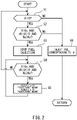
- control performed by the controller 51 is described with reference to FIG. 2 .
- the controller 51 determines whether or not a depression amount ⁇ of the accelerator pedal 52 detected by the first depression amount detector 63 is zero (step SI). In a case where the controller 51 determines that the depression amount ⁇ of the accelerator pedal 52 is not zero (NO in step S1), the flow proceeds to step S6, in which the controller 51 controls the fuel injection valves 21a to inject the fuel corresponding to the depression amount ⁇ of the accelerator pedal 52 into the engine 21.
- step S6 the controller 51 controls the pump regulator 23 and the motor regulator 25, such that the displacement q P of the pump 22 and the displacement q M of the motor 24 change in accordance with the vehicle speed V detected by the vehicle speed detector 62 as illustrated in a graph shown in FIG. 4 .
- step S1 determines whether or not a particular downhill travel condition is satisfied based on the result of the detection by the vehicle speed detector 62 and the result of the detection by the rotation number detector 61.
- the particular downhill travel condition includes three individual conditions. That is, the particular downhill travel condition being satisfied means the three individual conditions holding true at the same time.
- the first individual condition is that the vehicle speed V detected by the vehicle speed detector 62 is higher than a setting value Vs.
- the second individual condition is that a derivative value of the vehicle speed V (dV / dt) is greater than zero (i.e., the vehicle is increasing its speed).
- the third individual condition is that the number of rotations Ne of the engine 21 detected by the rotation number detector 61 is greater than a setting value Ns.
- the setting value Vs compared with the vehicle speed V is a value greater than V2 in FIG. 4 , which is the boundary between the high speed region and the medium speed region.
- the setting value Ns compared with the number of rotations Ne of the engine 21 is a value greater than the aforementioned number of rotations that is kept constant in the low and medium speed regions.
- step S2 determines that the particular downhill travel condition is satisfied (YES in step S2)
- step S3 determines that the particular downhill travel condition is not satisfied (NO in step S2)
- step S6 the controller 51 controls the fuel injection valves 21a to inject the fuel in such an amount that the number of engine rotations can be maintained as the number of engine rotations for idling.
- step S3 the controller 51 controls the fuel injection valves 21a to stop fuel injection into the engine 21. Then, after the fuel injection is stopped, the controller 51 determines whether or not the particular downhill travel condition is still satisfied (step S4).
- step S4 determines that the particular downhill travel condition is still satisfied after the fuel injection is stopped.
- step S5 determines that the particular downhill travel condition is not satisfied after the fuel injection is stopped.
- step S5 the controller 51 controls the motor regulator 25 to increase the displacement q M of the motor 24 by a predetermined amount, and controls the pump regulator 23 to decrease the displacement q P of the pump 22 by a predetermined amount. Thereafter, the flow returns to step S4, and the controller 51 repeats step S5 until the particular downhill travel condition is no longer satisfied. Accordingly, in a case where the particular downhill travel condition is satisfied, the displacement q M of the motor 24 increases gradually, and also, the displacement q P of the pump 22 decreases gradually.
- FIG. 3A to FIG. 3D show temporal changes in the number of rotations Ne of the engine 21, the displacement q P of the pump 22, the displacement q M of the motor 24, and the vehicle speed V in a case where: the vehicle speed V is in the high speed region; the vehicle is traveling on a downward slope, and the accelerator pedal 52 is not depressed.
- FIG. 3A to FIG. 3D as a result of the above-described control, when the vehicle speed V exceeds the setting value Vs, the engine brake is applied, and thereafter, increase in the number of rotations Ne of the engine 21 and increase in the vehicle speed V are suppressed.
- FIG. 3B to FIG. 3D at a point when increase in the vehicle speed V stops (NO in step S4), increase in the displacement q M of the motor 24 and decrease in the displacement q P of the pump 22 are stopped.
- the displacement q M of the motor 24 is increased, and thereby the speed reduction ratio is increased.
- the engine brake is applied for as long a time as possible. As a result, wear of the slide member of the mechanical brake is reduced.
- the controller 51 decreases the displacement q P of the pump 22 when increasing the displacement q M of the motor 24. Therefore, in this case, the speed reduction ratio at the time of using the engine brake is higher than in a case where the displacement q P of the pump 22 is kept constant. This makes it possible to increase the braking force of the engine brake.
- the controller 51 may increase the displacement q M of the motor 24 without decreasing the displacement q P of the pump 22.
- a HST system is a HST system for use in traveling of a vehicle.
- the HST system includes: a variable displacement motor that drives traveling means; a motor regulator that changes a displacement of the motor; a variable displacement pump connected to the motor such that a closed loop is formed, the variable displacement pump being driven by an engine; a pump regulator that changes a displacement of the pump; a depression amount detector that detects a depression amount of an accelerator pedal; a vehicle speed detector that detects a vehicle speed of the vehicle; a rotation number detector that detects a number of rotations of the engine per unit time; and a controller that controls the motor regulator and the pump regulator.
- the controller determines whether or not a particular downhill travel condition is satisfied based on a result of detection by the vehicle speed detector and a result of detection by the rotation number detector; and in a case where the depression amount of the accelerator pedal, which is detected by the depression amount detector, is zero and the particular downhill travel condition is satisfied, controls the motor regulator to increase the displacement of the motor.
- the particular downhill travel condition may include: a condition that the vehicle speed detected by the vehicle speed detector is higher than a setting value; a condition that a derivative value of the vehicle speed is greater than zero; and a condition that the number of rotations of the engine, which is detected by the rotation number detector, is greater than a setting value.
- the controller may control a fuel injection valve of the engine.
- the controller may: in a case where the depression amount of the accelerator pedal, which is detected by the depression amount detector, is zero and the particular downhill travel condition is satisfied, control the fuel injection valve to stop fuel injection into the engine; and in a case where the particular downhill travel condition is still satisfied after the fuel injection into the engine is stopped, control the motor regulator to increase the displacement of the motor.
- the controller may control the pump regulator to decrease the displacement of the pump when controlling the motor regulator to increase the displacement of the motor. According to this configuration, the speed reduction ratio at the time of using the engine brake is higher than in a case where the displacement of the pump is kept constant. This makes it possible to increase the braking force of the engine brake.
Landscapes
- Engineering & Computer Science (AREA)
- General Engineering & Computer Science (AREA)
- Mechanical Engineering (AREA)
- Chemical & Material Sciences (AREA)
- Combustion & Propulsion (AREA)
- Control Of Fluid Gearings (AREA)
- Control Of Vehicle Engines Or Engines For Specific Uses (AREA)
- Electrical Control Of Air Or Fuel Supplied To Internal-Combustion Engine (AREA)
Applications Claiming Priority (2)
| Application Number | Priority Date | Filing Date | Title |
|---|---|---|---|
| JP2019230263A JP2021099122A (ja) | 2019-12-20 | 2019-12-20 | 静油圧無段変速システム |
| PCT/JP2020/043946 WO2021124825A1 (fr) | 2019-12-20 | 2020-11-26 | Système de transmission à variation continue hydrostatique |
Publications (3)
| Publication Number | Publication Date |
|---|---|
| EP4080032A1 true EP4080032A1 (fr) | 2022-10-26 |
| EP4080032A4 EP4080032A4 (fr) | 2023-12-27 |
| EP4080032B1 EP4080032B1 (fr) | 2025-08-06 |
Family
ID=76476591
Family Applications (1)
| Application Number | Title | Priority Date | Filing Date |
|---|---|---|---|
| EP20903352.1A Active EP4080032B1 (fr) | 2019-12-20 | 2020-11-26 | Système de transmission à variation continue hydrostatique |
Country Status (4)
| Country | Link |
|---|---|
| US (1) | US11952952B2 (fr) |
| EP (1) | EP4080032B1 (fr) |
| JP (1) | JP2021099122A (fr) |
| WO (1) | WO2021124825A1 (fr) |
Families Citing this family (2)
| Publication number | Priority date | Publication date | Assignee | Title |
|---|---|---|---|---|
| EP3587254B1 (fr) * | 2018-06-28 | 2021-11-17 | GE Avio S.r.l. | Système et procédé de commande de servo-moteur électro-hydraulique, en particulier d'un moteur de turbopropulseur |
| IT202300002616A1 (it) * | 2023-02-15 | 2024-08-15 | Cnh Ind Italia Spa | Metodo di controllo di una trasmissione idraulica di un veicolo da lavoro o agricolo |
Family Cites Families (29)
| Publication number | Priority date | Publication date | Assignee | Title |
|---|---|---|---|---|
| US3665787A (en) * | 1970-07-24 | 1972-05-30 | Perkins Services Nv | Power plant |
| JPS5293869A (en) * | 1976-02-02 | 1977-08-06 | Aisin Seiki Co Ltd | Mechanical-hydraulic change gear |
| US4365473A (en) * | 1980-08-20 | 1982-12-28 | Caterpillar Tractor Co. | Hydrostatic transmission having an overspeed control |
| JPS6218335A (ja) | 1985-07-17 | 1987-01-27 | Shimadzu Corp | 車両用減速制御システム |
| JP2522219B2 (ja) * | 1991-03-01 | 1996-08-07 | 株式会社島津製作所 | 無段変速機のクラッチ制御機構 |
| JP2962112B2 (ja) * | 1993-08-20 | 1999-10-12 | トヨタ自動車株式会社 | 車両用駆動力制御装置 |
| US5517410A (en) | 1993-07-08 | 1996-05-14 | Toyota Jidosha Kabushiki Kaisha | Apparatus for controlling vehicle drive force depending upon vehicle load determined by engine load and vehicle speed |
| JP3400178B2 (ja) * | 1995-03-31 | 2003-04-28 | 日立建機株式会社 | 油圧駆動車両の走行制御装置 |
| DE69821750T2 (de) * | 1997-04-18 | 2006-06-22 | Transport Energy Systems Pty. Ltd., Holland Park | Hybridantriebssystem zur Verwendung im Fahrzeugbetrieb |
| JPH10311412A (ja) * | 1997-05-13 | 1998-11-24 | Daikin Ind Ltd | 車両用変速機の変速制御装置 |
| EP1029183B1 (fr) * | 1997-11-12 | 2008-01-02 | Folsom Technologies, Inc. | Machine hydraulique |
| JP3631620B2 (ja) | 1998-08-26 | 2005-03-23 | 新キャタピラー三菱株式会社 | 車両の走行速度制御装置 |
| JP2001235032A (ja) * | 2000-02-24 | 2001-08-31 | Komatsu Ltd | 油圧走行駆動装置 |
| JP4136488B2 (ja) * | 2002-06-26 | 2008-08-20 | 株式会社小松製作所 | 油圧駆動車の車速制御装置およびその制御方法 |
| JP2006312924A (ja) * | 2005-04-04 | 2006-11-16 | Denso Corp | クルーズ制御装置 |
| JP4528238B2 (ja) * | 2005-09-30 | 2010-08-18 | 株式会社クボタ | 作業車の車速制御構造 |
| US8322481B2 (en) * | 2006-12-28 | 2012-12-04 | Hitachi Construction Machinery Co., Ltd. | Traveling control apparatus for hydraulic traveling vehicle |
| WO2008123376A1 (fr) * | 2007-03-30 | 2008-10-16 | Komatsu Ltd. | Organe de commande de véhicule avec transmission à variation continue hydrostatique |
| JP4674592B2 (ja) * | 2007-04-02 | 2011-04-20 | アイシン・エィ・ダブリュ株式会社 | 車輌の変速制御装置 |
| JP5274581B2 (ja) | 2008-12-17 | 2013-08-28 | 株式会社小松製作所 | 静油圧式変速車両の制御装置 |
| US9140356B2 (en) | 2012-07-04 | 2015-09-22 | Kanzaki Kokyukoki Mfg. Co., Ltd. | Travel control unit of working vehicle |
| JP6142168B2 (ja) * | 2012-07-04 | 2017-06-07 | 株式会社 神崎高級工機製作所 | 作業車両の走行制御装置 |
| US9303633B2 (en) * | 2012-09-14 | 2016-04-05 | Caterpillar Inc. | Over-speed control system and method |
| US8948982B2 (en) * | 2013-01-31 | 2015-02-03 | Caterpillar Inc. | Open loop machine motor speed control based on downhill slope determination |
| US9688276B2 (en) * | 2015-02-26 | 2017-06-27 | Caterpillar Inc. | System and method for controlling engine and transmission system of a machine |
| JP2018178919A (ja) * | 2017-04-18 | 2018-11-15 | トヨタ自動車株式会社 | 車両の制御装置 |
| US10808839B2 (en) * | 2018-01-24 | 2020-10-20 | Cnh Industrial America Llc | Method and system for controlling a hydrostatic drive system of an agricultural vehicle |
| JP7193288B2 (ja) * | 2018-09-28 | 2022-12-20 | 日立建機株式会社 | 作業車両 |
| JP2020172792A (ja) * | 2019-04-11 | 2020-10-22 | 株式会社小松製作所 | 作業機械および制御方法 |
-
2019
- 2019-12-20 JP JP2019230263A patent/JP2021099122A/ja active Pending
-
2020
- 2020-11-26 EP EP20903352.1A patent/EP4080032B1/fr active Active
- 2020-11-26 WO PCT/JP2020/043946 patent/WO2021124825A1/fr not_active Ceased
- 2020-11-26 US US17/785,276 patent/US11952952B2/en active Active
Also Published As
| Publication number | Publication date |
|---|---|
| US11952952B2 (en) | 2024-04-09 |
| WO2021124825A1 (fr) | 2021-06-24 |
| EP4080032B1 (fr) | 2025-08-06 |
| EP4080032A4 (fr) | 2023-12-27 |
| JP2021099122A (ja) | 2021-07-01 |
| US20230022177A1 (en) | 2023-01-26 |
Similar Documents
| Publication | Publication Date | Title |
|---|---|---|
| US7841442B2 (en) | Hydrostatic transmission | |
| CN111492112B (zh) | 一种作业机械 | |
| CN103502698B (zh) | 作业车辆及作业车辆的控制方法 | |
| US20080184703A1 (en) | Method for regulating a hydrostatic drive system | |
| US8607919B2 (en) | Working vehicle and method for controlling a working vehicle | |
| US11035462B2 (en) | Work vehicle and control method for work vehicle | |
| US11261962B2 (en) | Hydrostatic travel drive and method for controlling the hydrostatic travel drive | |
| JPH06174081A (ja) | 自動推進駆動のための駆動機構 | |
| US11905680B2 (en) | Drive for a machine | |
| EP4080032B1 (fr) | Système de transmission à variation continue hydrostatique | |
| US20140244117A1 (en) | System and method for controlling a hydrostatic drive unit of a work vehicle | |
| CN113272193B (zh) | 作业机械以及作业机械的控制方法 | |
| CN111731266B (zh) | 基于车轮滑移的轮缘拉力极限 | |
| CN113302102B (zh) | 作业机械以及作业机械的控制方法 | |
| CN118715390A (zh) | 用于控制电动液压传动装置的装置和方法 | |
| EP4650534A1 (fr) | Engin de travaux et procédé de commande d'engin de travaux | |
| US12480282B2 (en) | Method of controlling hydraulic device | |
| EP1217128A1 (fr) | Système de gestion de puissance |
Legal Events
| Date | Code | Title | Description |
|---|---|---|---|
| STAA | Information on the status of an ep patent application or granted ep patent |
Free format text: STATUS: THE INTERNATIONAL PUBLICATION HAS BEEN MADE |
|
| PUAI | Public reference made under article 153(3) epc to a published international application that has entered the european phase |
Free format text: ORIGINAL CODE: 0009012 |
|
| STAA | Information on the status of an ep patent application or granted ep patent |
Free format text: STATUS: REQUEST FOR EXAMINATION WAS MADE |
|
| 17P | Request for examination filed |
Effective date: 20220704 |
|
| AK | Designated contracting states |
Kind code of ref document: A1 Designated state(s): AL AT BE BG CH CY CZ DE DK EE ES FI FR GB GR HR HU IE IS IT LI LT LU LV MC MK MT NL NO PL PT RO RS SE SI SK SM TR |
|
| DAV | Request for validation of the european patent (deleted) | ||
| DAX | Request for extension of the european patent (deleted) | ||
| A4 | Supplementary search report drawn up and despatched |
Effective date: 20231128 |
|
| RIC1 | Information provided on ipc code assigned before grant |
Ipc: F16H 61/431 20100101ALI20231122BHEP Ipc: F16H 61/421 20100101ALI20231122BHEP Ipc: F16H 61/21 20060101ALI20231122BHEP Ipc: F02D 29/04 20060101ALI20231122BHEP Ipc: F02D 29/02 20060101ALI20231122BHEP Ipc: F02D 41/12 20060101AFI20231122BHEP |
|
| REG | Reference to a national code |
Ref country code: DE Ref legal event code: R079 Free format text: PREVIOUS MAIN CLASS: F02D0041120000 Ipc: F02D0029020000 Ref document number: 602020056240 Country of ref document: DE |
|
| GRAP | Despatch of communication of intention to grant a patent |
Free format text: ORIGINAL CODE: EPIDOSNIGR1 |
|
| STAA | Information on the status of an ep patent application or granted ep patent |
Free format text: STATUS: GRANT OF PATENT IS INTENDED |
|
| RIC1 | Information provided on ipc code assigned before grant |
Ipc: F16H 61/431 20100101ALI20250324BHEP Ipc: F16H 61/421 20100101ALI20250324BHEP Ipc: F16H 61/21 20060101ALI20250324BHEP Ipc: F02D 41/12 20060101ALI20250324BHEP Ipc: F02D 29/04 20060101ALI20250324BHEP Ipc: F02D 29/02 20060101AFI20250324BHEP |
|
| INTG | Intention to grant announced |
Effective date: 20250403 |
|
| GRAS | Grant fee paid |
Free format text: ORIGINAL CODE: EPIDOSNIGR3 |
|
| GRAA | (expected) grant |
Free format text: ORIGINAL CODE: 0009210 |
|
| STAA | Information on the status of an ep patent application or granted ep patent |
Free format text: STATUS: THE PATENT HAS BEEN GRANTED |
|
| AK | Designated contracting states |
Kind code of ref document: B1 Designated state(s): AL AT BE BG CH CY CZ DE DK EE ES FI FR GB GR HR HU IE IS IT LI LT LU LV MC MK MT NL NO PL PT RO RS SE SI SK SM TR |
|
| REG | Reference to a national code |
Ref country code: GB Ref legal event code: FG4D |
|
| REG | Reference to a national code |
Ref country code: CH Ref legal event code: EP |
|
| REG | Reference to a national code |
Ref country code: DE Ref legal event code: R096 Ref document number: 602020056240 Country of ref document: DE |
|
| REG | Reference to a national code |
Ref country code: IE Ref legal event code: FG4D |
|
| REG | Reference to a national code |
Ref country code: NL Ref legal event code: MP Effective date: 20250806 |
|
| PG25 | Lapsed in a contracting state [announced via postgrant information from national office to epo] |
Ref country code: IS Free format text: LAPSE BECAUSE OF FAILURE TO SUBMIT A TRANSLATION OF THE DESCRIPTION OR TO PAY THE FEE WITHIN THE PRESCRIBED TIME-LIMIT Effective date: 20251206 |
|
| PGFP | Annual fee paid to national office [announced via postgrant information from national office to epo] |
Ref country code: DE Payment date: 20251118 Year of fee payment: 6 |
|
| PG25 | Lapsed in a contracting state [announced via postgrant information from national office to epo] |
Ref country code: NO Free format text: LAPSE BECAUSE OF FAILURE TO SUBMIT A TRANSLATION OF THE DESCRIPTION OR TO PAY THE FEE WITHIN THE PRESCRIBED TIME-LIMIT Effective date: 20251106 |
|
| REG | Reference to a national code |
Ref country code: LT Ref legal event code: MG9D |
|
| PG25 | Lapsed in a contracting state [announced via postgrant information from national office to epo] |
Ref country code: PT Free format text: LAPSE BECAUSE OF FAILURE TO SUBMIT A TRANSLATION OF THE DESCRIPTION OR TO PAY THE FEE WITHIN THE PRESCRIBED TIME-LIMIT Effective date: 20251209 |
|
| PG25 | Lapsed in a contracting state [announced via postgrant information from national office to epo] |
Ref country code: FI Free format text: LAPSE BECAUSE OF FAILURE TO SUBMIT A TRANSLATION OF THE DESCRIPTION OR TO PAY THE FEE WITHIN THE PRESCRIBED TIME-LIMIT Effective date: 20250806 |
|
| PG25 | Lapsed in a contracting state [announced via postgrant information from national office to epo] |
Ref country code: HR Free format text: LAPSE BECAUSE OF FAILURE TO SUBMIT A TRANSLATION OF THE DESCRIPTION OR TO PAY THE FEE WITHIN THE PRESCRIBED TIME-LIMIT Effective date: 20250806 Ref country code: NL Free format text: LAPSE BECAUSE OF FAILURE TO SUBMIT A TRANSLATION OF THE DESCRIPTION OR TO PAY THE FEE WITHIN THE PRESCRIBED TIME-LIMIT Effective date: 20250806 |
|
| PG25 | Lapsed in a contracting state [announced via postgrant information from national office to epo] |
Ref country code: GR Free format text: LAPSE BECAUSE OF FAILURE TO SUBMIT A TRANSLATION OF THE DESCRIPTION OR TO PAY THE FEE WITHIN THE PRESCRIBED TIME-LIMIT Effective date: 20251107 |
|
| PG25 | Lapsed in a contracting state [announced via postgrant information from national office to epo] |
Ref country code: SE Free format text: LAPSE BECAUSE OF FAILURE TO SUBMIT A TRANSLATION OF THE DESCRIPTION OR TO PAY THE FEE WITHIN THE PRESCRIBED TIME-LIMIT Effective date: 20250806 |
|
| PG25 | Lapsed in a contracting state [announced via postgrant information from national office to epo] |
Ref country code: LV Free format text: LAPSE BECAUSE OF FAILURE TO SUBMIT A TRANSLATION OF THE DESCRIPTION OR TO PAY THE FEE WITHIN THE PRESCRIBED TIME-LIMIT Effective date: 20250806 |
|
| PG25 | Lapsed in a contracting state [announced via postgrant information from national office to epo] |
Ref country code: PL Free format text: LAPSE BECAUSE OF FAILURE TO SUBMIT A TRANSLATION OF THE DESCRIPTION OR TO PAY THE FEE WITHIN THE PRESCRIBED TIME-LIMIT Effective date: 20250806 Ref country code: BG Free format text: LAPSE BECAUSE OF FAILURE TO SUBMIT A TRANSLATION OF THE DESCRIPTION OR TO PAY THE FEE WITHIN THE PRESCRIBED TIME-LIMIT Effective date: 20250806 |
|
| PG25 | Lapsed in a contracting state [announced via postgrant information from national office to epo] |
Ref country code: RS Free format text: LAPSE BECAUSE OF FAILURE TO SUBMIT A TRANSLATION OF THE DESCRIPTION OR TO PAY THE FEE WITHIN THE PRESCRIBED TIME-LIMIT Effective date: 20251106 |
|
| PG25 | Lapsed in a contracting state [announced via postgrant information from national office to epo] |
Ref country code: ES Free format text: LAPSE BECAUSE OF FAILURE TO SUBMIT A TRANSLATION OF THE DESCRIPTION OR TO PAY THE FEE WITHIN THE PRESCRIBED TIME-LIMIT Effective date: 20250806 |
|
| REG | Reference to a national code |
Ref country code: AT Ref legal event code: MK05 Ref document number: 1822072 Country of ref document: AT Kind code of ref document: T Effective date: 20250806 |
|
| PG25 | Lapsed in a contracting state [announced via postgrant information from national office to epo] |
Ref country code: RO Free format text: LAPSE BECAUSE OF FAILURE TO SUBMIT A TRANSLATION OF THE DESCRIPTION OR TO PAY THE FEE WITHIN THE PRESCRIBED TIME-LIMIT Effective date: 20250806 |
|
| PG25 | Lapsed in a contracting state [announced via postgrant information from national office to epo] |
Ref country code: SM Free format text: LAPSE BECAUSE OF FAILURE TO SUBMIT A TRANSLATION OF THE DESCRIPTION OR TO PAY THE FEE WITHIN THE PRESCRIBED TIME-LIMIT Effective date: 20250806 |
|
| PG25 | Lapsed in a contracting state [announced via postgrant information from national office to epo] |
Ref country code: DK Free format text: LAPSE BECAUSE OF FAILURE TO SUBMIT A TRANSLATION OF THE DESCRIPTION OR TO PAY THE FEE WITHIN THE PRESCRIBED TIME-LIMIT Effective date: 20250806 |
|
| PG25 | Lapsed in a contracting state [announced via postgrant information from national office to epo] |
Ref country code: AT Free format text: LAPSE BECAUSE OF FAILURE TO SUBMIT A TRANSLATION OF THE DESCRIPTION OR TO PAY THE FEE WITHIN THE PRESCRIBED TIME-LIMIT Effective date: 20250806 |
|
| PG25 | Lapsed in a contracting state [announced via postgrant information from national office to epo] |
Ref country code: IT Free format text: LAPSE BECAUSE OF FAILURE TO SUBMIT A TRANSLATION OF THE DESCRIPTION OR TO PAY THE FEE WITHIN THE PRESCRIBED TIME-LIMIT Effective date: 20250806 |
|
| PG25 | Lapsed in a contracting state [announced via postgrant information from national office to epo] |
Ref country code: CZ Free format text: LAPSE BECAUSE OF FAILURE TO SUBMIT A TRANSLATION OF THE DESCRIPTION OR TO PAY THE FEE WITHIN THE PRESCRIBED TIME-LIMIT Effective date: 20250806 |
|
| PG25 | Lapsed in a contracting state [announced via postgrant information from national office to epo] |
Ref country code: EE Free format text: LAPSE BECAUSE OF FAILURE TO SUBMIT A TRANSLATION OF THE DESCRIPTION OR TO PAY THE FEE WITHIN THE PRESCRIBED TIME-LIMIT Effective date: 20250806 Ref country code: SK Free format text: LAPSE BECAUSE OF FAILURE TO SUBMIT A TRANSLATION OF THE DESCRIPTION OR TO PAY THE FEE WITHIN THE PRESCRIBED TIME-LIMIT Effective date: 20250806 |