EP4096009A1 - Batterie, elektrische vorrichtung und verfahren und vorrichtung zur herstellung einer batterie - Google Patents
Batterie, elektrische vorrichtung und verfahren und vorrichtung zur herstellung einer batterie Download PDFInfo
- Publication number
- EP4096009A1 EP4096009A1 EP21916654.3A EP21916654A EP4096009A1 EP 4096009 A1 EP4096009 A1 EP 4096009A1 EP 21916654 A EP21916654 A EP 21916654A EP 4096009 A1 EP4096009 A1 EP 4096009A1
- Authority
- EP
- European Patent Office
- Prior art keywords
- battery
- wall
- battery cell
- groove
- pressure relief
- Prior art date
- Legal status (The legal status is an assumption and is not a legal conclusion. Google has not performed a legal analysis and makes no representation as to the accuracy of the status listed.)
- Granted
Links
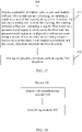
Images


Classifications
-
- H—ELECTRICITY
- H01—ELECTRIC ELEMENTS
- H01M—PROCESSES OR MEANS, e.g. BATTERIES, FOR THE DIRECT CONVERSION OF CHEMICAL ENERGY INTO ELECTRICAL ENERGY
- H01M50/00—Constructional details or processes of manufacture of the non-active parts of electrochemical cells other than fuel cells, e.g. hybrid cells
- H01M50/30—Arrangements for facilitating escape of gases
- H01M50/342—Non-re-sealable arrangements
- H01M50/3425—Non-re-sealable arrangements in the form of rupturable membranes or weakened parts, e.g. pierced with the aid of a sharp member
-
- H—ELECTRICITY
- H01—ELECTRIC ELEMENTS
- H01M—PROCESSES OR MEANS, e.g. BATTERIES, FOR THE DIRECT CONVERSION OF CHEMICAL ENERGY INTO ELECTRICAL ENERGY
- H01M10/00—Secondary cells; Manufacture thereof
- H01M10/04—Construction or manufacture in general
- H01M10/0422—Cells or battery with cylindrical casing
-
- H—ELECTRICITY
- H01—ELECTRIC ELEMENTS
- H01M—PROCESSES OR MEANS, e.g. BATTERIES, FOR THE DIRECT CONVERSION OF CHEMICAL ENERGY INTO ELECTRICAL ENERGY
- H01M10/00—Secondary cells; Manufacture thereof
- H01M10/04—Construction or manufacture in general
- H01M10/0431—Cells with wound or folded electrodes
-
- H—ELECTRICITY
- H01—ELECTRIC ELEMENTS
- H01M—PROCESSES OR MEANS, e.g. BATTERIES, FOR THE DIRECT CONVERSION OF CHEMICAL ENERGY INTO ELECTRICAL ENERGY
- H01M10/00—Secondary cells; Manufacture thereof
- H01M10/05—Accumulators with non-aqueous electrolyte
- H01M10/058—Construction or manufacture
- H01M10/0587—Construction or manufacture of accumulators having only wound construction elements, i.e. wound positive electrodes, wound negative electrodes and wound separators
-
- H—ELECTRICITY
- H01—ELECTRIC ELEMENTS
- H01M—PROCESSES OR MEANS, e.g. BATTERIES, FOR THE DIRECT CONVERSION OF CHEMICAL ENERGY INTO ELECTRICAL ENERGY
- H01M50/00—Constructional details or processes of manufacture of the non-active parts of electrochemical cells other than fuel cells, e.g. hybrid cells
- H01M50/10—Primary casings; Jackets or wrappings
- H01M50/102—Primary casings; Jackets or wrappings characterised by their shape or physical structure
- H01M50/103—Primary casings; Jackets or wrappings characterised by their shape or physical structure prismatic or rectangular
-
- H—ELECTRICITY
- H01—ELECTRIC ELEMENTS
- H01M—PROCESSES OR MEANS, e.g. BATTERIES, FOR THE DIRECT CONVERSION OF CHEMICAL ENERGY INTO ELECTRICAL ENERGY
- H01M50/00—Constructional details or processes of manufacture of the non-active parts of electrochemical cells other than fuel cells, e.g. hybrid cells
- H01M50/10—Primary casings; Jackets or wrappings
- H01M50/102—Primary casings; Jackets or wrappings characterised by their shape or physical structure
- H01M50/107—Primary casings; Jackets or wrappings characterised by their shape or physical structure having curved cross-section, e.g. round or elliptic
-
- H—ELECTRICITY
- H01—ELECTRIC ELEMENTS
- H01M—PROCESSES OR MEANS, e.g. BATTERIES, FOR THE DIRECT CONVERSION OF CHEMICAL ENERGY INTO ELECTRICAL ENERGY
- H01M50/00—Constructional details or processes of manufacture of the non-active parts of electrochemical cells other than fuel cells, e.g. hybrid cells
- H01M50/10—Primary casings; Jackets or wrappings
- H01M50/147—Lids or covers
- H01M50/148—Lids or covers characterised by their shape
- H01M50/152—Lids or covers characterised by their shape for cells having curved cross-section, e.g. round or elliptic
-
- H—ELECTRICITY
- H01—ELECTRIC ELEMENTS
- H01M—PROCESSES OR MEANS, e.g. BATTERIES, FOR THE DIRECT CONVERSION OF CHEMICAL ENERGY INTO ELECTRICAL ENERGY
- H01M50/00—Constructional details or processes of manufacture of the non-active parts of electrochemical cells other than fuel cells, e.g. hybrid cells
- H01M50/20—Mountings; Secondary casings or frames; Racks, modules or packs; Suspension devices; Shock absorbers; Transport or carrying devices; Holders
- H01M50/204—Racks, modules or packs for multiple batteries or multiple cells
- H01M50/207—Racks, modules or packs for multiple batteries or multiple cells characterised by their shape
- H01M50/209—Racks, modules or packs for multiple batteries or multiple cells characterised by their shape adapted for prismatic or rectangular cells
-
- H—ELECTRICITY
- H01—ELECTRIC ELEMENTS
- H01M—PROCESSES OR MEANS, e.g. BATTERIES, FOR THE DIRECT CONVERSION OF CHEMICAL ENERGY INTO ELECTRICAL ENERGY
- H01M50/00—Constructional details or processes of manufacture of the non-active parts of electrochemical cells other than fuel cells, e.g. hybrid cells
- H01M50/20—Mountings; Secondary casings or frames; Racks, modules or packs; Suspension devices; Shock absorbers; Transport or carrying devices; Holders
- H01M50/204—Racks, modules or packs for multiple batteries or multiple cells
- H01M50/207—Racks, modules or packs for multiple batteries or multiple cells characterised by their shape
- H01M50/213—Racks, modules or packs for multiple batteries or multiple cells characterised by their shape adapted for cells having curved cross-section, e.g. round or elliptic
-
- H—ELECTRICITY
- H01—ELECTRIC ELEMENTS
- H01M—PROCESSES OR MEANS, e.g. BATTERIES, FOR THE DIRECT CONVERSION OF CHEMICAL ENERGY INTO ELECTRICAL ENERGY
- H01M50/00—Constructional details or processes of manufacture of the non-active parts of electrochemical cells other than fuel cells, e.g. hybrid cells
- H01M50/20—Mountings; Secondary casings or frames; Racks, modules or packs; Suspension devices; Shock absorbers; Transport or carrying devices; Holders
- H01M50/249—Mountings; Secondary casings or frames; Racks, modules or packs; Suspension devices; Shock absorbers; Transport or carrying devices; Holders specially adapted for aircraft or vehicles, e.g. cars or trains
-
- H—ELECTRICITY
- H01—ELECTRIC ELEMENTS
- H01M—PROCESSES OR MEANS, e.g. BATTERIES, FOR THE DIRECT CONVERSION OF CHEMICAL ENERGY INTO ELECTRICAL ENERGY
- H01M50/00—Constructional details or processes of manufacture of the non-active parts of electrochemical cells other than fuel cells, e.g. hybrid cells
- H01M50/20—Mountings; Secondary casings or frames; Racks, modules or packs; Suspension devices; Shock absorbers; Transport or carrying devices; Holders
- H01M50/271—Lids or covers for the racks or secondary casings
-
- H—ELECTRICITY
- H01—ELECTRIC ELEMENTS
- H01M—PROCESSES OR MEANS, e.g. BATTERIES, FOR THE DIRECT CONVERSION OF CHEMICAL ENERGY INTO ELECTRICAL ENERGY
- H01M50/00—Constructional details or processes of manufacture of the non-active parts of electrochemical cells other than fuel cells, e.g. hybrid cells
- H01M50/30—Arrangements for facilitating escape of gases
- H01M50/375—Vent means sensitive to or responsive to temperature
-
- H—ELECTRICITY
- H01—ELECTRIC ELEMENTS
- H01M—PROCESSES OR MEANS, e.g. BATTERIES, FOR THE DIRECT CONVERSION OF CHEMICAL ENERGY INTO ELECTRICAL ENERGY
- H01M2220/00—Batteries for particular applications
- H01M2220/20—Batteries in motive systems, e.g. vehicle, ship, plane
-
- Y—GENERAL TAGGING OF NEW TECHNOLOGICAL DEVELOPMENTS; GENERAL TAGGING OF CROSS-SECTIONAL TECHNOLOGIES SPANNING OVER SEVERAL SECTIONS OF THE IPC; TECHNICAL SUBJECTS COVERED BY FORMER USPC CROSS-REFERENCE ART COLLECTIONS [XRACs] AND DIGESTS
- Y02—TECHNOLOGIES OR APPLICATIONS FOR MITIGATION OR ADAPTATION AGAINST CLIMATE CHANGE
- Y02E—REDUCTION OF GREENHOUSE GAS [GHG] EMISSIONS, RELATED TO ENERGY GENERATION, TRANSMISSION OR DISTRIBUTION
- Y02E60/00—Enabling technologies; Technologies with a potential or indirect contribution to GHG emissions mitigation
- Y02E60/10—Energy storage using batteries
Definitions
- This application relates to the technical field of energy storage components, and in particular, to a battery, an electrical device, and a method and device for manufacturing a battery.
- Lithium batteries are widely used due to advantages such as a small size, a high energy density, a high power density, reusability for many cycles, and a long shelf life.
- a battery is in abnormal use, for example, when the battery is overcharged or when an abnormal short circuit occurs inside the battery, an internal temperature and pressure is prone to rise, and a housing of the battery is at a risk of cracking or even explosion due to inability to withstand the internal pressure.
- a pressure relief region is usually disposed at an end cap of a battery cell.
- a battery in use is usually in the form of a battery module formed by connecting a plurality of battery cells in series, parallel, or series-and-parallel pattern. Therefore, when an internal pressure or temperature of the housing of the battery cell reaches a threshold, the internal pressure released by the battery cell in the pressure relief region is prone to impact another battery cell that is adjacent. The impact is prone to break the other battery cell or even cause a secondary explosion accident, thereby reducing safety and reliability of the battery in use.
- This application discloses a battery, an electrical device, and a method and device for manufacturing a battery to improve safety of the battery.
- a battery including: a plurality of battery cells arranged along a first direction.
- Each battery cell includes an end cap and a housing, an opening is made at an end of the housing along the first direction, the end cap is configured to close the opening, and the housing includes a first wall extending along the first direction.
- a pressure relief region is provided on the first wall. The pressure relief region is configured to release pressure along a second direction when an internal pressure or temperature of the battery cell reaches a threshold. The second direction intersects the first direction.
- a plurality of battery cells are arranged along the first direction.
- the end cap is mounted at the end of the housing along the first direction.
- the pressure relief region is provided on the first wall of the housing, the first wall extending along the first direction.
- the battery cell releases the internal pressure in the pressure relief region when the internal pressure or temperature in the housing of the battery cell reaches the threshold.
- the internal pressure can be released outward along the second direction intersecting the first direction. In this way, the pressure released from the pressure relief region will not impact an adjacent battery cell or damage other battery cells, thereby improving the safety of the battery.
- the pressure relief region of the first wall includes a fragile portion.
- the pressure relief region is configured to break the fragile portion to release the pressure when the internal pressure or temperature of the battery cell reaches the threshold.
- the fragile portion is formed on the first wall by making a first groove in the pressure relief region. A thickness of the fragile portion is less than a thickness of a remaining part of the first wall.
- the first groove can be formed in the pressure relief region of the first wall by stamping, milling, laser engraving, and other processing methods.
- the structure is simple, and the processing is convenient, thereby helping to reduce the manufacturing cost.
- the first groove is made on an outer surface of the housing, and/or the first groove is made on an inner surface of the housing.
- the existing processing method can hardly achieve a preset processing depth of the first groove when the first groove is made on only the inner surface or only the outer surface of the first wall.
- the battery cell is a cylindrical structure, and a bottom side of the first groove is a curved face, or a bottom side of the first groove is a flat face.
- the thickness of the fragile portion is equalized at all positions, and the structural strength of the fragile portion is relatively consistent.
- the internal pressure or temperature of the battery cell reaches the threshold, the internal pressure can be evenly released from all positions of the fragile portion.
- the bottom side of the first groove is a flat face, the structure is conveniently processible, and the thickness of the fragile portion gradually decreases from flanks to center in the width direction.
- the fragile portion is ruptured at a thinnest position.
- the structural strength of the fragile portion is relatively high, and the fragile portion is not prone to rupture under an external force other than the internal pressure or temperature.
- a second groove is made at a bottom side of the first groove.
- the thickness of the fragile portion at the second groove is less than the thickness of the remaining part of the fragile portion.
- the pressure relief region is configured to break a bottom side of the second groove to release the pressure when the internal pressure or temperature of the battery cell reaches the threshold.
- the thickness of the fragile portion at the second groove is less than the thickness of the remaining part of the fragile portion. Therefore, the structural strength of the fragile portion is high, and the battery cell is blasted at the bottom side of the second groove, thereby achieving an effect of directional blasting.
- the first wall includes a through-hole extending along the second direction and a pressure relief sheet covering the through-hole.
- the fragile portion is disposed on the pressure relief sheet.
- the fragile portion may be processed and formed on the pressure relief sheet first, and then mounted on the first wall through the pressure relief sheet.
- the structural processing and design of the fragile portion are not prone to be affected by the shape of the housing of the battery cell, thereby helping to reduce the difficulty of processing and manufacturing the fragile portion.
- the first wall further includes a body portion, and the body portion and the fragile portion are integrally formed.
- the first groove extends along the first direction.
- a ratio of a dimension of the first groove in the first direction to a dimension of the first wall in the first direction is greater than 1/3.
- the gas inside the battery cell generally concentrates at a position close to two ends along the first direction. If the ratio of the dimension of the first groove in the first direction to the dimension of the first wall in the first direction is greater, the fragile portion formed by making the first groove in the pressure relief region is closer to positions at the two ends of the battery cell along the first direction. This effectively shortens a pressure relief path of the gas inside the battery cell, so that the battery cell can release pressure quickly in time when the internal temperature or pressure of the battery cell reaches the threshold.
- the first groove is an annular structure.
- the first groove made in an annular shape, when the internal pressure or temperature of the battery cell reaches the threshold, the area of releasing pressure outward from the battery cell is increased, so that the internal pressure of the battery cell can be released quickly to avoid violent explosion, thereby improving the safety of the battery cell.
- the first groove is disposed around a central axis of the battery cell, the central axis being parallel to the first direction.
- the fragile portion is disposed as a circle around the central axis of the battery cell, the central axis being parallel to the first direction.
- the battery cell can release pressure outward from all positions surrounded by the fragile portion, thereby helping to shorten the path of gas exhausting and pressure release and improve the pressure release efficiency.
- the first groove includes a first part and a second part that are in communication with each other.
- the fragile portion includes a first fragile portion formed by disposing the first part and a second fragile portion formed by disposing the second part.
- a thickness of the first fragile portion is less than a thickness of the second fragile portion.
- the pressure relief region is configured to break the first fragile portion and avoid breaking at least a part of the second fragile portion when the internal pressure or temperature of the battery cell reaches the threshold.
- the first fragile portion is broken, but at least a part of the second fragile portion remains unbroken, thereby avoiding flying debris generated by the housing when the fragile portion is completely broken, and ensuring the safety of the battery cell.
- the first wall includes two fragile portions spaced apart along the first direction in the pressure relief region.
- the area of releasing pressure is increased in the pressure relief region, the pressure relief capability of the battery cell is improved, and the safety of the battery is further improved.
- a spacing between two fragile portions along the first direction is set based on a capacity of the battery cell.
- the housing further includes a second wall.
- the second wall and the end cap are connected to two ends of the first wall respectively, the two ends being opposite to each other along the first direction.
- the battery cell further includes an electrode assembly. After being wound, the electrode assembly includes a first end face contiguous to the end cap and a second end face contiguous to the second wall in the first direction.
- At least a part of the pressure relief region is a region located between the first end face and the end cap along the first direction on the first wall.
- the gas inside the battery cell is prone to concentrate at the two ends of the electrode assembly. Therefore, by disposing at least a part of the pressure relief region in the area that is on the first wall and between the first end face of the electrode assembly and the end cap, such embodiments can reduce the paths for releasing outward the pressure that is generated by the gas located between the end cap and the electrode terminal.
- At least a part of the pressure relief region is a region located between the second end face and the second wall along the first direction on the first wall.
- the gas inside the battery cell is prone to concentrate at the two ends of the electrode assembly. Therefore, by disposing at least a part of the pressure relief region in the area that is on the first wall and between the second end face of the electrode assembly and the second wall, such embodiments can reduce the paths for releasing outward the pressure that is generated by the gas located between the second wall and the second end face of the electrode terminal.
- an electrical device including the battery described above.
- the battery is configured to provide electrical energy.
- a method for manufacturing a battery including: providing a plurality of battery cells, where each battery cell includes an end cap and a housing, an opening is made at an end of the housing along a first direction, the end cap is configured to close the opening, the housing includes a first wall extending along the first direction, a pressure relief region is provided on the first wall, the pressure relief region is configured to release pressure along a second direction when an internal pressure or temperature of the battery cell reaches a threshold, and the second direction intersects the first direction; and arranging the plurality of battery cells along the first direction.
- a plurality of battery cells are arranged along the first direction.
- the end cap is mounted at the end of the housing along the first direction.
- the pressure relief region is provided on the first wall of the housing, the first wall extending along the first direction.
- the battery cell releases the internal pressure in the pressure relief region when the internal pressure or temperature in the housing of the battery cell reaches the threshold.
- the internal pressure can be released outward along the second direction intersecting the first direction. In this way, the pressure released from the pressure relief region will not impact an adjacent battery cell or damage other battery cells, thereby improving the safety of the battery.
- a device for manufacturing a battery including: a battery cell manufacturing module, configured to manufacture battery cells, where each battery cell includes: an end cap and a housing, an opening is made at an end of the housing along a first direction, the end cap is configured to close the opening, the housing includes a first wall extending along the first direction, a pressure relief region is provided on the first wall, the pressure relief region is configured to release pressure along a second direction when an internal pressure or temperature of the battery cell reaches a threshold, and the second direction intersects the first direction; and an assembling module, configured to arrange a plurality of battery cells along the first direction.
- a plurality of referred to in this application means two or more (including two).
- a plurality of groups means two or more groups (including two groups)
- a plurality of pieces means two or more pieces (including two pieces).
- a battery cell and a battery including a plurality of battery cells are applicable to various devices that use a battery as a power supply, for example, a mobile phone, a portable device, a notebook computer, an electric power cart, an electric vehicle, a ship, a spacecraft, an electric toy, an electric tool.
- the spacecraft may include an airplane, a rocket, a space shuttle, a spaceship, and the like.
- the electric toy may include a fixed or mobile electric toy, such as a game console, an electric car toy, an electric ship toy, an electric airplane toy, and the like.
- the electric tool may include an electric tool for metal cutting, an electric grinding tool, an electric assembly tool, an electric tool for railways, such as an electric drill, an electric grinder, an electric wrench, an electric screwdriver, an electric hammer, an electric impact drill, a concrete vibrator, an electric planer, and the like.
- the battery cell and the battery including a plurality of battery cells according to embodiments of this application are not only applicable to the devices described above, but also applicable to all battery-powered devices. However, for brevity, the following embodiments are described by using a vehicle 100 as an example.
- FIG. 1 is a schematic structural diagram of a vehicle 100 according to an embodiment of this application.
- the vehicle 100 may be an oil-fueled vehicle, a natural gas vehicle, or a new energy vehicle.
- the new energy vehicle may be a battery electric vehicle, a hybrid electric vehicle, a range-extended electric vehicle, or the like.
- a battery 200 may be disposed inside the vehicle 100.
- the battery 200 may be a battery pack or a battery module.
- the battery 200 may be disposed at the bottom, front, or rear of the vehicle 100.
- the controller 110 and the motor 120 may be further disposed inside the vehicle 100.
- the controller 110 may be configured to control the battery 200 to supply power to the motor 120. Through a transmission mechanism, the motor 120 may drive wheels of the vehicle 100 to run.
- the battery 200 may be configured to supply power to the vehicle 100.
- the battery 200 may serve as an operating power supply of the vehicle 100 to power a circuit system of the vehicle 100.
- the battery may be configured to meet operating power usage requirements of the vehicle 100 that is being started or navigated or running.
- the battery 200 serves not only as an operating power supply of the vehicle 100, but may also serve as a drive power supply of the vehicle 100 to provide driving motive power for the vehicle 100 in place of or partially in place of oil or natural gas.
- FIG. 2 is a schematic structural exploded view of a battery 200 according to an embodiment of this application.
- the battery 200 may include one or more battery cells 300.
- the plurality of battery cells 300 may be connected in series, parallel, or series-and-parallel pattern.
- the series-and-parallel pattern means a combination of series connection and parallel connection.
- the plurality of battery cells 300 may be connected in series, parallel, or series-and-parallel pattern to form a battery module (or referred to as a battery group) first, and then a plurality of battery modules may be connected in series, parallel, or series-and-parallel pattern to form the battery 200.
- the battery 200 may be directly formed of a plurality of battery cells 300, or the battery cells may form a battery module first and then a plurality of battery modules form the battery 200.
- the battery 200 includes a plurality of battery cells 300.
- the battery 200 further includes a box.
- the interior of the box is a hollow structure.
- a plurality of battery cells 300 are accommodated in the box.
- the box may further include a first cover portion 210 and a second cover portion 220.
- the first cover portion 210 and the second cover portion 220 are snap-fitted together.
- the plurality of battery cells 300 are connected in series, parallel, or series-and-parallel pattern, and then placed in an accommodation space formed by snap-fitting the first cover portion 210 and the second cover portion 220.
- the plurality of battery cells 300 may be placed in the box horizontally or vertically. As an example in this application, a plurality of battery cells 300 are placed in the box horizontally.
- FIG. 3 is a schematic diagram of a connection structure between one battery cell 300 and another battery cell 300 in a battery 200 according to an embodiment of this application.
- the battery 200 may further include other structures.
- the battery 200 may further include a busbar component 230 configured to implement electrical connection between the plurality of battery cells 300.
- the battery cell 300 may be in a cylindrical shape, a flat shape, a cuboidal shape, or other shapes. As an example in this application, the battery cell 300 is a cylinder.
- FIG. 4 is a schematic structural exploded view of an existing battery cell 300.
- An electrode assembly 310 and an electrolytic solution are disposed in the battery cell 300.
- the electrode assembly 310 may be formed by stacking or winding a positive electrode plate, a negative electrode plate, and a separator together.
- the battery cell 300 works primarily by the movement of metal ions in the electrolytic solution between the positive electrode plate and the negative electrode plate.
- the separator is an insulator located between the positive electrode plate and the negative electrode plate.
- the positive electrode plate and the negative electrode plate each include a coated region and an uncoated region. A positive active material is coated on the coated region of the positive electrode plate, and a negative active material is coated on the coated region of the negative electrode plate.
- the active materials are coated on a current collector formed of a metal sheet. No active material is coated on the uncoated region.
- the positive electrode plate includes a positive current collector and a positive active material layer.
- the positive active material layer is coated on a surface of the positive current collector.
- a part that is of the current collector and that is not coated with the positive active material layer protrudes from a part that is of the current collector and that is coated with the positive active material layer.
- the part that is of the current collector and that is not coated with the positive active material layer serves as a positive tab.
- the negative electrode plate includes a negative current collector and a negative active material layer. The negative active material layer is coated on a surface of the negative current collector.
- a part that is of the current collector and that is not coated with the negative active material layer protrudes from a part that is of the current collector and that is coated with the negative active material layer.
- the part that is of the current collector and that is not coated with the negative active material layer serves as a negative tab.
- the battery cell 300 further includes an end cap 320 and a housing 330.
- An opening is made on the housing 330.
- An inner space in communication with the opening is provided in the housing 330.
- the inner space may be configured to accommodate the electrode assembly 310 and the electrolytic solution.
- the end cap 320 fits onto the opening of the housing 330 to seal the electrode assembly 310 and the electrolytic solution in the housing 330.
- An electrode terminal is disposed on the end cap 320. The electrode terminal is electrically connected to a positive tab or a negative tab in the electrode assembly 310 by a connector adapter.
- a pressure relief position 350 is usually disposed on the battery cell 300.
- the pressure relief position 350 is a pressure relief region actuated to relieve the internal pressure or temperature when the internal pressure or temperature of the battery cell 300 reaches a preset threshold, and is also referred to as a pressure relief region.
- the pressure relief region may be in the form of an explosion-proof valve, a gas valve, a pressure relief valve, a safety valve, or the like, and may specifically adopt a pressure-sensitive or temperature-sensitive element or structure.
- the pressure relief region is actuated or a fragile structure disposed in the pressure relief region is broken to form an opening or channel for relieving the internal pressure or temperature.
- the pressure relief region of the battery cell 300 is usually disposed on the end cap 320. That is, both the pressure relief region and the electrode terminal are located on the end cap 320.
- a plurality of battery cells 300 are usually connected in series, parallel, or series-and-parallel pattern to form a battery module, and one battery cell 300 is usually connected to another battery cell 300 in an end-to-end opposition way.
- the pressure relief region is ruptured when thermal runaway occurs due to overcharge or abnormal short circuit inside the battery cell 300.
- another battery cell 300 that is adjacent is prone to be impacted. The impact causes the other battery cell 300 to break, or even results in a secondary explosion accident, thereby reducing the safety and reliability of the battery 200 in use.
- this application optimizes the structure and position of the pressure relief region.
- FIG. 5 is a schematic structural diagram of a battery cell 300 according to some embodiments of this application.
- the battery 200 includes a plurality of battery cells 300.
- the plurality of battery cells 300 are arranged along the first direction.
- Each battery cell 300 includes an end cap 320 and a housing 330.
- An opening is made at the end of the housing 330 along the first direction.
- the end cap 320 is configured to seal the opening.
- the housing 330 includes a first wall extending in the first direction.
- a pressure relief region is provided on the first wall. The pressure relief region is configured to release pressure along a second direction when the internal pressure or temperature of the battery cell 300 reaches the threshold.
- the second direction intersects the first direction.
- the battery cell 300 may be a cylindrical structure, a cuboidal structure, or other structures. That is, the housing 330 of the battery cell 300 may be a cylindrical structure, or a cuboidal structure, or other structures.
- the first direction may be a length direction of the battery cell 300 (the X-axis direction in the drawing).
- the number of openings of the housing 330 may be one or two.
- the opening is made at both ends of the housing 330 along the length direction separately.
- the number of the end caps 320 is also two.
- One of the two end caps 320 fits onto the opening at one end of the housing 330.
- the other fits onto the opening at the other end of the housing 330.
- the opening is made at one of two ends of the housing 330 along the length direction, but not made at the other end.
- the end cap 320 fits onto the opened end of the housing 330.
- the first wall may be a cylindrical surface of the cylindrical housing 330.
- the first wall may be at least one of four sidewalls of the cuboidal housing 330.
- the first wall may be parallel to the first direction, or may be at a preset angle to the first direction.
- the first wall is parallel to the first direction.
- that the first direction intersects the second direction may be that the first direction is perpendicular to the second direction.
- the first direction may be at a preset angle such as 45° to the second direction, without being specifically limited herein.
- the second direction may be a radial direction of the battery cell 300.
- a plurality of battery cells 300 are arranged along the first direction.
- the end cap 320 is mounted at the end of the housing 330 along the first direction.
- the pressure relief region is provided on the first wall of the housing 330, the first wall being parallel to the first direction.
- conductive materials splattered from the pressure relief region are not likely to be splattered onto the busbar component 230 of the adjacent battery 200, where the busbar component is independently located between the ends and is configured to electrically connect the battery cells 300. This can effectively prevent a second accident caused by a short circuit between the battery cells 300 arising from the conductive materials.
- the first wall includes a fragile portion 331 in the pressure relief region.
- the fragile portion 331 is broken to release the internal pressure of the battery cell 300.
- the fragile portion 331 may be formed on the first wall by applying a material in the pressure relief region with a structural strength lower than the structural strength of the body portion of the first wall; or, the fragile portion 332 may be formed by disposing a pressure relief component or a pressure relief mechanism in the pressure relief region, or the like, as long as the internal pressure of the battery cell 300 can be released when the internal temperature or pressure of the battery cell 300 reaches the threshold.
- FIG. 6 to FIG. 9 are schematic structural sectional views of a housing 330 sectioned along an A-A direction according to some embodiments of this application.
- the fragile portion 331 is formed on the first wall by making a first groove 332 in the pressure relief region.
- a thickness h1 of the fragile portion 331 is less than a thickness h0 of a remaining part of the first wall.
- the first groove 332 may be a groove of various shapes, such as a linear shape, an X shape, an annular shape, without being limited to the examples. As shown in FIG. 5 , the first groove 332 shown in FIG. 5 is a linear structure.
- the structural strength at the position of the first groove 332 is reduced to form the fragile portion 331.
- the first groove 332 can be formed in the pressure relief region of the first wall by stamping, milling, laser engraving, and other processing methods. The structure is simple, and the processing is convenient, thereby helping to reduce the manufacturing cost.
- FIG. 6 is a schematic structural sectional view of a housing 330 sectioned along an A-A direction when the first groove 332 is made on an outer surface of the first wall.
- the first groove 332 may be made on the outer surface of the first wall, and/or the first groove 332 is made on an inner surface of the housing 330.
- the first groove 332 is in a linear shape and the housing 330 is a cylindrical structure.
- the first groove 332 is made on the outer surface of the first wall.
- the inner space of the housing 330 of the battery cell 300 is limited, and brings inconvenience to the processing operation of the first groove 332. Therefore, the first groove 332 made on the outer surface of the first wall increases the external space, widens the field of vision, and facilitates visual observation and the processing of the first groove 332.
- FIG. 7 is a schematic structural sectional view of a housing 330 sectioned along an A-A direction when the first groove 332 is made on the inner surface of the first wall. In this way, the first groove 332 is prevented from being exposed outside the housing 330, thereby improving visual appearance of the battery cell 300.
- FIG. 8 is a schematic structural sectional view of a housing 330 sectioned along an A-A direction when the first groove 332 is made on both the inner surface and the outer surface of the first wall.
- the first groove 332 is made on both the inner surface and the outer surface of the first wall.
- the first groove 332 on the inner surface corresponds to the first groove on the outer surface of the first wall.
- the battery cell 300 is a cylindrical structure, and a bottom side of the first groove 332 is a curved face, or a bottom side of the first groove 332 is a flat face.
- the bottom side of the first groove 332 means a wall face perpendicular to the second direction in the first groove 332.
- FIG. 6 to FIG. 8 are schematic structural sectional views of a housing 330 sectioned along an A-A direction when the bottom wall of the first groove is parallel to the inner surface and/or outer surface of the first wall.
- the bottom side of the first groove 332 is a curved face parallel to the inner surface or the outer surface of the first wall, the thickness of the fragile portion 331 is equalized at all positions, and the structural strength of the fragile portion 331 is relatively consistent.
- the bottom side of the first groove 332 may be a curved face that is not parallel to the outer surface or the inner surface of the first wall.
- FIG. 9 is a schematic structural sectional view of a housing 330 sectioned along an A-A direction when the bottom side of the first groove 332 is a flat face.
- the bottom side of the first groove 332 may be a flat face instead.
- the first groove 332 with this structure is conveniently processible.
- the thickness of the fragile portion 331 gradually decreases from flanks to center in the width direction. When the internal pressure or temperature of the battery cell 300 reaches the threshold, the fragile portion 331 is ruptured at a thinnest position.
- the structural strength of the fragile portion 331 with this structure is relatively high, and the fragile portion 331 is not prone to rupture under an external force other than the internal pressure or temperature.
- the structure in which the bottom side of the first groove 332 is a curved face or a flat face is not only applicable to the battery cell 300 with a cylindrical structure, but also applicable to the battery cell 300 with a cuboidal structure or other structures.
- FIG. 10 is a schematic structural exploded view of a battery cell 300 according to some embodiments of this application.
- the first wall includes a through-hole 333 extending along the first direction and a pressure relief sheet 340 covering the through-hole 333.
- the fragile portion 331 is disposed on the pressure relief sheet 340.
- the pressure relief sheet 340 fits onto the through-hole 333 of the first wall to seal the through-hole 333.
- the pressure relief sheet 340 may be fixed onto the first wall by welding such as laser welding, ultrasonic welding, or the like.
- the fragile portion 331 may be processed and formed on the pressure relief sheet 340 first, and then mounted on the first wall through the pressure relief sheet 340.
- the structural processing and design of the fragile portion 331 are not prone to be affected by the shape of the housing 330 of the battery cell 300, thereby helping to reduce the difficulty of processing and manufacturing the fragile portion 331.
- the first wall further includes a body portion.
- the body portion and the fragile portion 331 are integrally formed.
- the fragile portion 331 and the first wall are an integrated structure.
- the first groove 332 extends along the first direction.
- a ratio of a dimension of the first groove 332 in the first direction to a dimension of the first wall in the first direction is greater than 1/3.
- the ratio of the length of the first groove 332 in the first direction to the length of the first wall in the first direction is 1/3.
- the gas pressure inside the battery cell 300 generally concentrates at a position close to two ends along the first direction. If the ratio of the dimension of the first groove 332 in the first direction to the dimension of the first wall in the first direction is greater, the fragile portion 331 formed by making the first groove 332 in the pressure relief region is closer to positions at the two ends of the battery cell 300 along the first direction. This effectively shortens a pressure relief path of the gas inside the battery cell 300, so that the battery cell 300 can release pressure quickly in time when the internal temperature or pressure of the battery cell 300 reaches the threshold.
- the first groove 332 is made in an annular shape. With the first groove 332 made in an annular shape, when the internal pressure or temperature of the battery cell 300 reaches the threshold, the housing 330 of the battery cell 300 can rupture along an annular edge, thereby increasing the area of releasing pressure outward from the battery cell 300. In this way, the internal pressure of the battery cell 300 can be released outward quickly in time, thereby improving the safety of the battery cell 300.
- first groove 332 may be in a regular annular shape, or in other irregular quasi-annular shapes.
- the first groove 332 is disposed around a central axis of the battery cell 300, the central axis being parallel to the first direction.
- the fragile portion 331 is disposed as a circle around the central axis of the battery cell 300, the central axis being parallel to the first direction.
- the battery cell 300 can release pressure outward from all positions surrounded by the fragile portion 331, thereby helping to shorten the path of gas exhausting and pressure release from inside to outside of the battery cell 300 and improve the pressure release efficiency.
- the central axis of the annular shape may intersect, for example, be perpendicular to, the first direction.
- the first groove 332 may be made on the inner surface of the first wall, or the outer surface of the first wall, or both the inner surface and the outer surface of the first wall. Therefore, for ease of description, as an example in the following embodiments, the first groove 332 is an annular shape and is made on the outer surface of the first wall.
- a second groove 3321 is further made at a bottom wall of the first groove 332.
- the thickness h2 of the fragile portion 331 at the second groove 3321 is less than the thickness h1 of the remaining part of the fragile portion 331.
- the pressure relief region is configured to break a bottom wall of the second groove 3321 to release the pressure when the internal pressure or temperature of the battery cell 300 reaches the threshold.
- the thickness h2 of the fragile portion 331 at the second groove 3321 is less than the thickness h1 of the remaining part of the fragile portion. Therefore, the structural strength of the fragile portion 331 is high, and the battery cell 300 is blasted at the bottom side of the second groove 3321 when the internal pressure or temperature of the battery cell reaches the threshold, thereby achieving an effect of directional blasting.
- the dimension of the second groove 3321 on the bottom side of the first groove 332 in the first direction may be less than or equal to the dimension of the first groove 332 in the first direction, without being specifically limited herein.
- the first groove 332 includes a first part 332a and a second part 332b.
- the first part 332a is in communication with the second part 332b.
- the fragile portion 331 includes a first fragile portion 331a and a second fragile portion 331b.
- the first fragile portion 331a formed by disposing the first part 332a in the pressure relief region
- the second fragile portion 331b is formed by disposing the second part 332b in the pressure relief region.
- a thickness h11 of the first fragile portion 331a is less than a thickness h12 of the second fragile portion 331b.
- the pressure relief region is configured to break the first fragile portion 331a and avoid breaking at least a part of the second fragile portion 331b when the internal pressure or temperature of the battery cell 300 reaches the threshold.
- the first part 332a and the second part 332b may each account for a percentage of the first groove 332, such as 1/2 of the first groove 332.
- the first groove 332 is disposed in an annular shape.
- the corresponding first part and second part each account for 1/2 of the length of the first groove.
- the allocation may be performed according to actual conditions.
- the first part 332a accounts for 2/3 of the first groove 332
- the second part 332b accounts for 1/3 of the first groove 332.
- the first fragile portion 331a is broken, but at least a part of the second fragile portion 331b remains unbroken, thereby avoiding flying debris generated by the housing when the fragile portion 331 is completely broken, and ensuring the safety of the battery cell.
- one part of the second groove 332 is made on the bottom wall of the first part 332a, and the other part of the second groove 332 is made on the bottom wall of the second part 332b.
- the first wall includes two fragile portions 331 in the pressure relief region.
- the two fragile portions 331 are spaced apart along the first direction.
- a spacing between the two fragile portions 331 along the first direction may be set based on a capacity of the battery cell 300. The higher the capacity of the battery cell 300, the larger the spacing between the two fragile portions 331 along the first direction. In other embodiments, the number of the fragile portions 331 disposed along the first direction in the pressure relief region may be selected depending on the capacity or dimension of the battery cell 300.
- FIG. 16 is a schematic structural exploded view of a battery cell according to other embodiments of this application.
- the housing 330 further includes a second wall.
- the second wall and the end cap 320 are connected to two ends of the first wall respectively, the two ends being opposite to each other along the first direction.
- the battery cell 300 further includes an electrode assembly 310. After being wound, the battery cell 300 includes a first end face 321 contiguous to the end cap 320 and a second end face 322 contiguous to the second wall in the first direction.
- the second wall may be another end cap 320 disposed at the other end of the housing 330, or may be a bottom wall disposed at the bottom of the housing 330.
- At least a part of the pressure relief region is a region located between the first end face 311 and the end cap 320 along the first direction on the first wall.
- a least a part of the fragile portion 331 is a region located between the first end face 311 and the end cap 320 that are opposite to each other on the first wall.
- the number of the fragile portions 331 may be one or more.
- the gas inside the battery cell 300 is prone to concentrate at the two ends of the electrode assembly 310. Therefore, with at least a part of the pressure relief region being located between the first end face of the electrode assembly 310 and the end cap 320 on the first wall, this application can reduce the paths for releasing outward the pressure that is generated by the gas located between the end cap 320 and the electrode assembly 310. In this way, the internal pressure of the battery cell 300 can be released quickly in time when the internal pressure or temperature of the battery cell 300 reaches the threshold.
- At least a part of the pressure relief region is a region located between the second end face 312 and the second wall along the first direction on the first wall. That is, a least a part of the fragile portion 331 is a region located between the second end face 312 and the second wall that are opposite to each other on the first wall.
- the number of the fragile portions 331 may be one or more.
- the gas inside the battery cell 300 is prone to concentrate at the two ends of the electrode assembly 310. Therefore, with at least a part of the pressure relief region being located between the second end face 312 of the electrode assembly 310 and the second wall on the first wall, this application can reduce the paths for releasing outward the pressure that is generated by the gas located between the second wall and the second end face 312 of the electrode assembly 310. In this way, the internal pressure of the battery cell 300 can be released quickly in time when the internal pressure or temperature of the battery cell 300 reaches the threshold.
- At least one fragile portion 331 is provided between the first end face 311 and the end cap 320 along the first direction on the first wall, and at least one fragile portion 331 is provided between the second end face 312 and the second wall along the first direction on the first wall. In this way, the gas at the two ends of the electrode assembly 310 can be released outward in time when the internal pressure or temperature of the battery reaches the threshold.
- the pressure relief region may be a region located between the first end face 311 and the second end face 312 along the first direction on the first wall. That is, the pressure relief region is located in the middle of the housing 330.
- the battery cell 300, the battery 200, and the vehicle 100 according to embodiments of this application have been described above.
- the following describes a method for manufacturing a battery cell 300 according to an embodiment of this application.
- FIG. 17 is a schematic flowchart of a method for manufacturing a battery according to an embodiment of this application.
- the method 400 includes the following steps:
- each battery cell 300 includes an end cap 320 and a housing 330.
- An opening is made at an end of the housing 330 along a first direction.
- the end cap 320 is configured to close the opening.
- the housing 330 includes a first wall extending along the first direction.
- a pressure relief region is provided on the first wall. The pressure relief region is configured to release pressure along a second direction when an internal pressure or temperature of the battery cell 300 reaches a threshold. The second direction intersects the first direction; and
- a plurality of battery cells 300 are arranged along the first direction.
- the end cap 320 is mounted at the end of the housing 330 along the first direction.
- the pressure relief region is provided on the first wall of the housing 330, the first wall being parallel to the first direction.
- FIG. 18 is a schematic structural block diagram of a device for manufacturing a battery according to an embodiment of this application.
- the device 500 includes a battery cell 300 manufacturing module 501 and an assembling module 502.
- the battery cell 300 manufacturing module 501 is configured to manufacture battery cells 300, where each battery cell 300 includes an end cap 320 and a housing 330. An opening is made at an end of the housing 330 along a first direction. The end cap 320 is configured to close the opening.
- the housing 330 includes a first wall extending along the first direction. A pressure relief region is provided on the first wall. The pressure relief region is configured to release pressure along a second direction when an internal pressure or temperature of the battery cell 300 reaches a threshold. The second direction intersects the first direction.
- the assembling module 502 is configured to arrange a plurality of battery cells 300 along the first direction.
Landscapes
- Chemical & Material Sciences (AREA)
- Chemical Kinetics & Catalysis (AREA)
- Electrochemistry (AREA)
- General Chemical & Material Sciences (AREA)
- Engineering & Computer Science (AREA)
- Manufacturing & Machinery (AREA)
- Aviation & Aerospace Engineering (AREA)
- Gas Exhaust Devices For Batteries (AREA)
- Sealing Battery Cases Or Jackets (AREA)
Applications Claiming Priority (1)
| Application Number | Priority Date | Filing Date | Title |
|---|---|---|---|
| PCT/CN2021/076293 WO2022170495A1 (zh) | 2021-02-09 | 2021-02-09 | 电池、用电装置、制备电池的方法和装置 |
Publications (3)
| Publication Number | Publication Date |
|---|---|
| EP4096009A1 true EP4096009A1 (de) | 2022-11-30 |
| EP4096009A4 EP4096009A4 (de) | 2023-05-10 |
| EP4096009B1 EP4096009B1 (de) | 2025-05-21 |
Family
ID=82837383
Family Applications (1)
| Application Number | Title | Priority Date | Filing Date |
|---|---|---|---|
| EP21916654.3A Active EP4096009B1 (de) | 2021-02-09 | 2021-02-09 | Batterie, elektrische vorrichtung und verfahren und vorrichtung zur herstellung einer batterie |
Country Status (5)
| Country | Link |
|---|---|
| US (1) | US12567645B2 (de) |
| EP (1) | EP4096009B1 (de) |
| CN (1) | CN115210950A (de) |
| HU (1) | HUE072138T2 (de) |
| WO (1) | WO2022170495A1 (de) |
Cited By (1)
| Publication number | Priority date | Publication date | Assignee | Title |
|---|---|---|---|---|
| EP4510321A1 (de) * | 2023-07-25 | 2025-02-19 | Eve Energy Co., Ltd. | Explosionssichere batterie |
Families Citing this family (8)
| Publication number | Priority date | Publication date | Assignee | Title |
|---|---|---|---|---|
| USD1079601S1 (en) * | 2022-07-18 | 2025-06-17 | Xiamen Hithium Energy Storage Technology Co., Ltd. | Cylindrical battery |
| USD1079600S1 (en) * | 2022-08-29 | 2025-06-17 | Xiamen Hithium Energy Storage Technology Co., Ltd. | Cylindrical battery |
| WO2024148518A1 (zh) * | 2023-01-10 | 2024-07-18 | 宁德时代新能源科技股份有限公司 | 电池单体、电池以及用电装置 |
| CN220984777U (zh) | 2023-05-09 | 2024-05-17 | 宁德时代新能源科技股份有限公司 | 电池单体、电池及用电设备 |
| CN116231221B (zh) * | 2023-05-09 | 2023-07-25 | 宁德时代新能源科技股份有限公司 | 电池单体、电池及用电设备 |
| CN119069896A (zh) | 2023-05-31 | 2024-12-03 | 宁德时代新能源科技股份有限公司 | 电池单体、电池及用电设备 |
| CN220627884U (zh) * | 2023-07-25 | 2024-03-19 | 株式会社Aesc日本 | 圆柱电芯、电池组及电子设备 |
| CN118431663B (zh) * | 2024-07-03 | 2024-11-19 | 浙江晶科储能有限公司 | 电池包及储能系统 |
Family Cites Families (11)
| Publication number | Priority date | Publication date | Assignee | Title |
|---|---|---|---|---|
| JPH06333548A (ja) * | 1993-05-19 | 1994-12-02 | Matsushita Electric Ind Co Ltd | 防爆型電池 |
| JPH10269997A (ja) * | 1997-03-21 | 1998-10-09 | Shin Kobe Electric Mach Co Ltd | 円筒密閉形蓄電池 |
| KR100551885B1 (ko) * | 2003-10-20 | 2006-02-10 | 삼성에스디아이 주식회사 | 리튬 이온 2차 전지 |
| US8236441B2 (en) * | 2007-07-24 | 2012-08-07 | A123 Systems, Inc. | Battery cell design and methods of its construction |
| JP5782225B2 (ja) * | 2010-03-24 | 2015-09-24 | 日立エーアイシー株式会社 | 蓄電デバイス |
| US9196920B2 (en) * | 2011-10-18 | 2015-11-24 | Johnson Controls Technology Llc | Electrochemical cell having a safety device |
| JP6536354B2 (ja) * | 2015-11-02 | 2019-07-03 | 株式会社村田製作所 | 電池、電池パック、電子機器、電動車両、蓄電装置および電力システム |
| PL3396750T3 (pl) * | 2015-12-24 | 2020-04-30 | Lg Chem, Ltd. | Kompozycja środka wiążącego dla akumulatora, i elektroda dla akumulatora i obejmujący ją akumulator litowy |
| CN205846021U (zh) * | 2016-05-20 | 2016-12-28 | 深圳市沃特玛电池有限公司 | 一种电池壳体及具有该壳体的电池 |
| DE102016212450A1 (de) * | 2016-07-08 | 2018-01-11 | Bayerische Motoren Werke Aktiengesellschaft | Gehäuseteil einer Batteriezelle oder für eine Batteriezelle sowie Verfahren zum Applizieren eines Berstelements an einem Gehäuseteil einer Batteriezelle |
| CN210245599U (zh) * | 2019-07-16 | 2020-04-03 | 常州微宙电子科技有限公司 | 一种针式锂离子电池 |
-
2021
- 2021-02-09 EP EP21916654.3A patent/EP4096009B1/de active Active
- 2021-02-09 WO PCT/CN2021/076293 patent/WO2022170495A1/zh not_active Ceased
- 2021-02-09 CN CN202180008113.4A patent/CN115210950A/zh active Pending
- 2021-02-09 HU HUE21916653A patent/HUE072138T2/hu unknown
-
2022
- 2022-07-28 US US17/815,570 patent/US12567645B2/en active Active
Cited By (1)
| Publication number | Priority date | Publication date | Assignee | Title |
|---|---|---|---|---|
| EP4510321A1 (de) * | 2023-07-25 | 2025-02-19 | Eve Energy Co., Ltd. | Explosionssichere batterie |
Also Published As
| Publication number | Publication date |
|---|---|
| EP4096009A4 (de) | 2023-05-10 |
| WO2022170495A1 (zh) | 2022-08-18 |
| US12567645B2 (en) | 2026-03-03 |
| CN115210950A (zh) | 2022-10-18 |
| US20220367968A1 (en) | 2022-11-17 |
| HUE072138T2 (hu) | 2025-10-28 |
| EP4096009B1 (de) | 2025-05-21 |
Similar Documents
| Publication | Publication Date | Title |
|---|---|---|
| US12567645B2 (en) | Battery, electrical device, and method and device for manufacturing battery | |
| EP4401206B1 (de) | Energiespeichervorrichtung mit batterieendabdeckungsanordnung, und elektrische vorrichtung | |
| EP4439838A1 (de) | Batteriezelle, batterie und elektrische vorrichtung | |
| EP4080661B1 (de) | Batteriezelle, batterie und energieverbrauchende vorrichtung | |
| EP4266480A1 (de) | Batteriezelle, batterie und elektrische vorrichtung | |
| US12597676B2 (en) | Battery cell, method and system for manufacturing battery cell, battery, and electrical device | |
| EP4167368A1 (de) | Druckentlastungsvorrichtung, batteriezelle, batterie und stromverbrauchende vorrichtung | |
| EP4087045B1 (de) | Batteriezelle, batterie, elektronische vorrichtung und herstellungsverfahren | |
| EP4675780A2 (de) | Endkappe, batteriezelle, batterie und stromverbrauchende vorrichtung | |
| EP4220788B1 (de) | Batteriezelle, batterie und elektrische vorrichtung | |
| US20250192347A1 (en) | Insulation film, battery cell, battery and electrical device | |
| EP4181279A1 (de) | Batteriezelle, verfahren und system zur herstellung davon, batterie und elektrische vorrichtung | |
| EP4507114A1 (de) | Laminierte elektrodenanordnung, batteriezelle, batterie und elektrische vorrichtung | |
| KR102937096B1 (ko) | 케이스, 배터리 셀, 배터리 및 전기 기기 | |
| US12463274B2 (en) | Battery cell, method and system for manufacturing same, battery, and electrical device | |
| EP4354649B1 (de) | Batteriezelle sowie verfahren zur herstellung einer batteriezelle | |
| EP4715966A1 (de) | Batteriezellengehäuse und herstellungsverfahren dafür, batteriezelle, batterie und elektrische vorrichtung | |
| EP4261987B1 (de) | Batteriezelle, batterie und elektrische vorrichtung | |
| EP4481911A1 (de) | Batteriezelle, batterie und elektrische vorrichtung | |
| EP4407757B1 (de) | Batteriezelle und herstellungsverfahren und herstellungssystem dafür, batterie und elektrische vorrichtung | |
| EP4184668A1 (de) | Druckentlastungsvorrichtung, batteriezelle, batterie und elektrische vorrichtung | |
| EP4510349A1 (de) | Endkappe, batteriezelle, batterie, elektrische vorrichtung und herstellungsverfahren | |
| AU2020463875A1 (en) | Battery cell, battery, and method and apparatus for preparing battery cell | |
| US20250337082A1 (en) | Battery cell, battery, power consumption device and manufacturing device and method for battery cell | |
| US12176571B2 (en) | Exhaust apparatus, battery cell, battery, and electric apparatus |
Legal Events
| Date | Code | Title | Description |
|---|---|---|---|
| STAA | Information on the status of an ep patent application or granted ep patent |
Free format text: STATUS: UNKNOWN |
|
| STAA | Information on the status of an ep patent application or granted ep patent |
Free format text: STATUS: THE INTERNATIONAL PUBLICATION HAS BEEN MADE |
|
| PUAI | Public reference made under article 153(3) epc to a published international application that has entered the european phase |
Free format text: ORIGINAL CODE: 0009012 |
|
| STAA | Information on the status of an ep patent application or granted ep patent |
Free format text: STATUS: REQUEST FOR EXAMINATION WAS MADE |
|
| 17P | Request for examination filed |
Effective date: 20220822 |
|
| AK | Designated contracting states |
Kind code of ref document: A1 Designated state(s): AL AT BE BG CH CY CZ DE DK EE ES FI FR GB GR HR HU IE IS IT LI LT LU LV MC MK MT NL NO PL PT RO RS SE SI SK SM TR |
|
| A4 | Supplementary search report drawn up and despatched |
Effective date: 20230413 |
|
| RIC1 | Information provided on ipc code assigned before grant |
Ipc: H01M 50/375 20210101ALI20230405BHEP Ipc: H01M 50/107 20210101ALI20230405BHEP Ipc: H01M 50/249 20210101ALI20230405BHEP Ipc: H01M 50/213 20210101ALI20230405BHEP Ipc: H01M 50/342 20210101AFI20230405BHEP |
|
| STAA | Information on the status of an ep patent application or granted ep patent |
Free format text: STATUS: EXAMINATION IS IN PROGRESS |
|
| 17Q | First examination report despatched |
Effective date: 20240213 |
|
| DAV | Request for validation of the european patent (deleted) | ||
| DAX | Request for extension of the european patent (deleted) | ||
| RAP1 | Party data changed (applicant data changed or rights of an application transferred) |
Owner name: CONTEMPORARY AMPEREX TECHNOLOGY(HONG KONG) LIMITED |
|
| GRAP | Despatch of communication of intention to grant a patent |
Free format text: ORIGINAL CODE: EPIDOSNIGR1 |
|
| STAA | Information on the status of an ep patent application or granted ep patent |
Free format text: STATUS: GRANT OF PATENT IS INTENDED |
|
| INTG | Intention to grant announced |
Effective date: 20250206 |
|
| GRAS | Grant fee paid |
Free format text: ORIGINAL CODE: EPIDOSNIGR3 |
|
| GRAA | (expected) grant |
Free format text: ORIGINAL CODE: 0009210 |
|
| STAA | Information on the status of an ep patent application or granted ep patent |
Free format text: STATUS: THE PATENT HAS BEEN GRANTED |
|
| AK | Designated contracting states |
Kind code of ref document: B1 Designated state(s): AL AT BE BG CH CY CZ DE DK EE ES FI FR GB GR HR HU IE IS IT LI LT LU LV MC MK MT NL NO PL PT RO RS SE SI SK SM TR |
|
| REG | Reference to a national code |
Ref country code: GB Ref legal event code: FG4D |
|
| P01 | Opt-out of the competence of the unified patent court (upc) registered |
Free format text: CASE NUMBER: APP_19257/2025 Effective date: 20250422 |
|
| REG | Reference to a national code |
Ref country code: CH Ref legal event code: EP |
|
| REG | Reference to a national code |
Ref country code: DE Ref legal event code: R096 Ref document number: 602021031304 Country of ref document: DE |
|
| REG | Reference to a national code |
Ref country code: IE Ref legal event code: FG4D |
|
| REG | Reference to a national code |
Ref country code: NL Ref legal event code: MP Effective date: 20250521 |
|
| PG25 | Lapsed in a contracting state [announced via postgrant information from national office to epo] |
Ref country code: ES Free format text: LAPSE BECAUSE OF FAILURE TO SUBMIT A TRANSLATION OF THE DESCRIPTION OR TO PAY THE FEE WITHIN THE PRESCRIBED TIME-LIMIT Effective date: 20250521 Ref country code: PT Free format text: LAPSE BECAUSE OF FAILURE TO SUBMIT A TRANSLATION OF THE DESCRIPTION OR TO PAY THE FEE WITHIN THE PRESCRIBED TIME-LIMIT Effective date: 20250922 Ref country code: FI Free format text: LAPSE BECAUSE OF FAILURE TO SUBMIT A TRANSLATION OF THE DESCRIPTION OR TO PAY THE FEE WITHIN THE PRESCRIBED TIME-LIMIT Effective date: 20250521 |
|
| REG | Reference to a national code |
Ref country code: LT Ref legal event code: MG9D |
|
| PG25 | Lapsed in a contracting state [announced via postgrant information from national office to epo] |
Ref country code: NO Free format text: LAPSE BECAUSE OF FAILURE TO SUBMIT A TRANSLATION OF THE DESCRIPTION OR TO PAY THE FEE WITHIN THE PRESCRIBED TIME-LIMIT Effective date: 20250821 Ref country code: GR Free format text: LAPSE BECAUSE OF FAILURE TO SUBMIT A TRANSLATION OF THE DESCRIPTION OR TO PAY THE FEE WITHIN THE PRESCRIBED TIME-LIMIT Effective date: 20250822 |
|
| PG25 | Lapsed in a contracting state [announced via postgrant information from national office to epo] |
Ref country code: PL Free format text: LAPSE BECAUSE OF FAILURE TO SUBMIT A TRANSLATION OF THE DESCRIPTION OR TO PAY THE FEE WITHIN THE PRESCRIBED TIME-LIMIT Effective date: 20250521 Ref country code: NL Free format text: LAPSE BECAUSE OF FAILURE TO SUBMIT A TRANSLATION OF THE DESCRIPTION OR TO PAY THE FEE WITHIN THE PRESCRIBED TIME-LIMIT Effective date: 20250521 |
|
| PG25 | Lapsed in a contracting state [announced via postgrant information from national office to epo] |
Ref country code: BG Free format text: LAPSE BECAUSE OF FAILURE TO SUBMIT A TRANSLATION OF THE DESCRIPTION OR TO PAY THE FEE WITHIN THE PRESCRIBED TIME-LIMIT Effective date: 20250521 |
|
| PG25 | Lapsed in a contracting state [announced via postgrant information from national office to epo] |
Ref country code: HR Free format text: LAPSE BECAUSE OF FAILURE TO SUBMIT A TRANSLATION OF THE DESCRIPTION OR TO PAY THE FEE WITHIN THE PRESCRIBED TIME-LIMIT Effective date: 20250521 |
|
| PG25 | Lapsed in a contracting state [announced via postgrant information from national office to epo] |
Ref country code: RS Free format text: LAPSE BECAUSE OF FAILURE TO SUBMIT A TRANSLATION OF THE DESCRIPTION OR TO PAY THE FEE WITHIN THE PRESCRIBED TIME-LIMIT Effective date: 20250821 |
|
| PG25 | Lapsed in a contracting state [announced via postgrant information from national office to epo] |
Ref country code: IS Free format text: LAPSE BECAUSE OF FAILURE TO SUBMIT A TRANSLATION OF THE DESCRIPTION OR TO PAY THE FEE WITHIN THE PRESCRIBED TIME-LIMIT Effective date: 20250921 |
|
| PG25 | Lapsed in a contracting state [announced via postgrant information from national office to epo] |
Ref country code: LV Free format text: LAPSE BECAUSE OF FAILURE TO SUBMIT A TRANSLATION OF THE DESCRIPTION OR TO PAY THE FEE WITHIN THE PRESCRIBED TIME-LIMIT Effective date: 20250521 |
|
| REG | Reference to a national code |
Ref country code: AT Ref legal event code: MK05 Ref document number: 1797605 Country of ref document: AT Kind code of ref document: T Effective date: 20250521 |
|
| PG25 | Lapsed in a contracting state [announced via postgrant information from national office to epo] |
Ref country code: AT Free format text: LAPSE BECAUSE OF FAILURE TO SUBMIT A TRANSLATION OF THE DESCRIPTION OR TO PAY THE FEE WITHIN THE PRESCRIBED TIME-LIMIT Effective date: 20250521 Ref country code: DK Free format text: LAPSE BECAUSE OF FAILURE TO SUBMIT A TRANSLATION OF THE DESCRIPTION OR TO PAY THE FEE WITHIN THE PRESCRIBED TIME-LIMIT Effective date: 20250521 Ref country code: SM Free format text: LAPSE BECAUSE OF FAILURE TO SUBMIT A TRANSLATION OF THE DESCRIPTION OR TO PAY THE FEE WITHIN THE PRESCRIBED TIME-LIMIT Effective date: 20250521 |
|
| PG25 | Lapsed in a contracting state [announced via postgrant information from national office to epo] |
Ref country code: CZ Free format text: LAPSE BECAUSE OF FAILURE TO SUBMIT A TRANSLATION OF THE DESCRIPTION OR TO PAY THE FEE WITHIN THE PRESCRIBED TIME-LIMIT Effective date: 20250521 |
|
| PG25 | Lapsed in a contracting state [announced via postgrant information from national office to epo] |
Ref country code: EE Free format text: LAPSE BECAUSE OF FAILURE TO SUBMIT A TRANSLATION OF THE DESCRIPTION OR TO PAY THE FEE WITHIN THE PRESCRIBED TIME-LIMIT Effective date: 20250521 |
|
| PG25 | Lapsed in a contracting state [announced via postgrant information from national office to epo] |
Ref country code: SK Free format text: LAPSE BECAUSE OF FAILURE TO SUBMIT A TRANSLATION OF THE DESCRIPTION OR TO PAY THE FEE WITHIN THE PRESCRIBED TIME-LIMIT Effective date: 20250521 |
|
| PG25 | Lapsed in a contracting state [announced via postgrant information from national office to epo] |
Ref country code: IT Free format text: LAPSE BECAUSE OF FAILURE TO SUBMIT A TRANSLATION OF THE DESCRIPTION OR TO PAY THE FEE WITHIN THE PRESCRIBED TIME-LIMIT Effective date: 20250521 |
|
| REG | Reference to a national code |
Ref country code: DE Ref legal event code: R097 Ref document number: 602021031304 Country of ref document: DE |
|
| PLBE | No opposition filed within time limit |
Free format text: ORIGINAL CODE: 0009261 |
|
| STAA | Information on the status of an ep patent application or granted ep patent |
Free format text: STATUS: NO OPPOSITION FILED WITHIN TIME LIMIT |
|
| REG | Reference to a national code |
Ref country code: CH Ref legal event code: L10 Free format text: ST27 STATUS EVENT CODE: U-0-0-L10-L00 (AS PROVIDED BY THE NATIONAL OFFICE) Effective date: 20260402 |
|
| PGFP | Annual fee paid to national office [announced via postgrant information from national office to epo] |
Ref country code: GB Payment date: 20260224 Year of fee payment: 6 |
|
| PGFP | Annual fee paid to national office [announced via postgrant information from national office to epo] |
Ref country code: DE Payment date: 20260223 Year of fee payment: 6 |
|
| PGFP | Annual fee paid to national office [announced via postgrant information from national office to epo] |
Ref country code: FR Payment date: 20260224 Year of fee payment: 6 |
|
| 26N | No opposition filed |
Effective date: 20260224 |