EP4134586A1 - Beleuchtungsvorrichtung zur abbildung einer virtuellen beleuchteten oberfläche eines kollektors - Google Patents
Beleuchtungsvorrichtung zur abbildung einer virtuellen beleuchteten oberfläche eines kollektors Download PDFInfo
- Publication number
- EP4134586A1 EP4134586A1 EP22198166.5A EP22198166A EP4134586A1 EP 4134586 A1 EP4134586 A1 EP 4134586A1 EP 22198166 A EP22198166 A EP 22198166A EP 4134586 A1 EP4134586 A1 EP 4134586A1
- Authority
- EP
- European Patent Office
- Prior art keywords
- light
- collector
- light source
- optical axis
- reflecting surface
- Prior art date
- Legal status (The legal status is an assumption and is not a legal conclusion. Google has not performed a legal analysis and makes no representation as to the accuracy of the status listed.)
- Granted
Links
Images

Classifications
-
- F—MECHANICAL ENGINEERING; LIGHTING; HEATING; WEAPONS; BLASTING
- F21—LIGHTING
- F21S—NON-PORTABLE LIGHTING DEVICES; SYSTEMS THEREOF; VEHICLE LIGHTING DEVICES SPECIALLY ADAPTED FOR VEHICLE EXTERIORS
- F21S41/00—Illuminating devices specially adapted for vehicle exteriors, e.g. headlamps
- F21S41/10—Illuminating devices specially adapted for vehicle exteriors, e.g. headlamps characterised by the light source
- F21S41/14—Illuminating devices specially adapted for vehicle exteriors, e.g. headlamps characterised by the light source characterised by the type of light source
- F21S41/141—Light emitting diodes [LED]
- F21S41/147—Light emitting diodes [LED] the main emission direction of the LED being angled to the optical axis of the illuminating device
-
- F—MECHANICAL ENGINEERING; LIGHTING; HEATING; WEAPONS; BLASTING
- F21—LIGHTING
- F21S—NON-PORTABLE LIGHTING DEVICES; SYSTEMS THEREOF; VEHICLE LIGHTING DEVICES SPECIALLY ADAPTED FOR VEHICLE EXTERIORS
- F21S41/00—Illuminating devices specially adapted for vehicle exteriors, e.g. headlamps
- F21S41/30—Illuminating devices specially adapted for vehicle exteriors, e.g. headlamps characterised by reflectors
- F21S41/32—Optical layout thereof
-
- B—PERFORMING OPERATIONS; TRANSPORTING
- B60—VEHICLES IN GENERAL
- B60Q—ARRANGEMENT OF SIGNALLING OR LIGHTING DEVICES, THE MOUNTING OR SUPPORTING THEREOF OR CIRCUITS THEREFOR, FOR VEHICLES IN GENERAL
- B60Q1/00—Arrangement of optical signalling or lighting devices, the mounting or supporting thereof or circuits therefor
- B60Q1/02—Arrangement of optical signalling or lighting devices, the mounting or supporting thereof or circuits therefor the devices being primarily intended to illuminate the way ahead or to illuminate other areas of way or environments
- B60Q1/04—Arrangement of optical signalling or lighting devices, the mounting or supporting thereof or circuits therefor the devices being primarily intended to illuminate the way ahead or to illuminate other areas of way or environments the devices being headlights
- B60Q1/14—Arrangement of optical signalling or lighting devices, the mounting or supporting thereof or circuits therefor the devices being primarily intended to illuminate the way ahead or to illuminate other areas of way or environments the devices being headlights having dimming means
-
- F—MECHANICAL ENGINEERING; LIGHTING; HEATING; WEAPONS; BLASTING
- F21—LIGHTING
- F21S—NON-PORTABLE LIGHTING DEVICES; SYSTEMS THEREOF; VEHICLE LIGHTING DEVICES SPECIALLY ADAPTED FOR VEHICLE EXTERIORS
- F21S41/00—Illuminating devices specially adapted for vehicle exteriors, e.g. headlamps
- F21S41/10—Illuminating devices specially adapted for vehicle exteriors, e.g. headlamps characterised by the light source
- F21S41/14—Illuminating devices specially adapted for vehicle exteriors, e.g. headlamps characterised by the light source characterised by the type of light source
- F21S41/141—Light emitting diodes [LED]
- F21S41/147—Light emitting diodes [LED] the main emission direction of the LED being angled to the optical axis of the illuminating device
- F21S41/148—Light emitting diodes [LED] the main emission direction of the LED being angled to the optical axis of the illuminating device the main emission direction of the LED being perpendicular to the optical axis
-
- F—MECHANICAL ENGINEERING; LIGHTING; HEATING; WEAPONS; BLASTING
- F21—LIGHTING
- F21S—NON-PORTABLE LIGHTING DEVICES; SYSTEMS THEREOF; VEHICLE LIGHTING DEVICES SPECIALLY ADAPTED FOR VEHICLE EXTERIORS
- F21S41/00—Illuminating devices specially adapted for vehicle exteriors, e.g. headlamps
- F21S41/20—Illuminating devices specially adapted for vehicle exteriors, e.g. headlamps characterised by refractors, transparent cover plates, light guides or filters
- F21S41/25—Projection lenses
-
- F—MECHANICAL ENGINEERING; LIGHTING; HEATING; WEAPONS; BLASTING
- F21—LIGHTING
- F21S—NON-PORTABLE LIGHTING DEVICES; SYSTEMS THEREOF; VEHICLE LIGHTING DEVICES SPECIALLY ADAPTED FOR VEHICLE EXTERIORS
- F21S41/00—Illuminating devices specially adapted for vehicle exteriors, e.g. headlamps
- F21S41/30—Illuminating devices specially adapted for vehicle exteriors, e.g. headlamps characterised by reflectors
- F21S41/32—Optical layout thereof
- F21S41/321—Optical layout thereof the reflector being a surface of revolution or a planar surface, e.g. truncated
-
- F—MECHANICAL ENGINEERING; LIGHTING; HEATING; WEAPONS; BLASTING
- F21—LIGHTING
- F21S—NON-PORTABLE LIGHTING DEVICES; SYSTEMS THEREOF; VEHICLE LIGHTING DEVICES SPECIALLY ADAPTED FOR VEHICLE EXTERIORS
- F21S41/00—Illuminating devices specially adapted for vehicle exteriors, e.g. headlamps
- F21S41/30—Illuminating devices specially adapted for vehicle exteriors, e.g. headlamps characterised by reflectors
- F21S41/32—Optical layout thereof
- F21S41/33—Multi-surface reflectors, e.g. reflectors with facets or reflectors with portions of different curvature
- F21S41/338—Multi-surface reflectors, e.g. reflectors with facets or reflectors with portions of different curvature the reflector having surface portions added to its general concavity
-
- F—MECHANICAL ENGINEERING; LIGHTING; HEATING; WEAPONS; BLASTING
- F21—LIGHTING
- F21S—NON-PORTABLE LIGHTING DEVICES; SYSTEMS THEREOF; VEHICLE LIGHTING DEVICES SPECIALLY ADAPTED FOR VEHICLE EXTERIORS
- F21S41/00—Illuminating devices specially adapted for vehicle exteriors, e.g. headlamps
- F21S41/30—Illuminating devices specially adapted for vehicle exteriors, e.g. headlamps characterised by reflectors
- F21S41/32—Optical layout thereof
- F21S41/36—Combinations of two or more separate reflectors
- F21S41/365—Combinations of two or more separate reflectors successively reflecting the light
-
- F—MECHANICAL ENGINEERING; LIGHTING; HEATING; WEAPONS; BLASTING
- F21—LIGHTING
- F21S—NON-PORTABLE LIGHTING DEVICES; SYSTEMS THEREOF; VEHICLE LIGHTING DEVICES SPECIALLY ADAPTED FOR VEHICLE EXTERIORS
- F21S41/00—Illuminating devices specially adapted for vehicle exteriors, e.g. headlamps
- F21S41/60—Illuminating devices specially adapted for vehicle exteriors, e.g. headlamps characterised by a variable light distribution
-
- F—MECHANICAL ENGINEERING; LIGHTING; HEATING; WEAPONS; BLASTING
- F21—LIGHTING
- F21V—FUNCTIONAL FEATURES OR DETAILS OF LIGHTING DEVICES OR SYSTEMS THEREOF; STRUCTURAL COMBINATIONS OF LIGHTING DEVICES WITH OTHER ARTICLES, NOT OTHERWISE PROVIDED FOR
- F21V13/00—Producing particular characteristics or distribution of the light emitted by means of a combination of elements specified in two or more of main groups F21V1/00 - F21V11/00
- F21V13/02—Combinations of only two kinds of elements
- F21V13/04—Combinations of only two kinds of elements the elements being reflectors and refractors
-
- F—MECHANICAL ENGINEERING; LIGHTING; HEATING; WEAPONS; BLASTING
- F21—LIGHTING
- F21V—FUNCTIONAL FEATURES OR DETAILS OF LIGHTING DEVICES OR SYSTEMS THEREOF; STRUCTURAL COMBINATIONS OF LIGHTING DEVICES WITH OTHER ARTICLES, NOT OTHERWISE PROVIDED FOR
- F21V5/00—Refractors for light sources
- F21V5/04—Refractors for light sources of lens shape
-
- F—MECHANICAL ENGINEERING; LIGHTING; HEATING; WEAPONS; BLASTING
- F21—LIGHTING
- F21V—FUNCTIONAL FEATURES OR DETAILS OF LIGHTING DEVICES OR SYSTEMS THEREOF; STRUCTURAL COMBINATIONS OF LIGHTING DEVICES WITH OTHER ARTICLES, NOT OTHERWISE PROVIDED FOR
- F21V7/00—Reflectors for light sources
- F21V7/04—Optical design
-
- F—MECHANICAL ENGINEERING; LIGHTING; HEATING; WEAPONS; BLASTING
- F21—LIGHTING
- F21W—INDEXING SCHEME ASSOCIATED WITH SUBCLASSES F21K, F21L, F21S and F21V, RELATING TO USES OR APPLICATIONS OF LIGHTING DEVICES OR SYSTEMS
- F21W2102/00—Exterior vehicle lighting devices for illuminating purposes
-
- F—MECHANICAL ENGINEERING; LIGHTING; HEATING; WEAPONS; BLASTING
- F21—LIGHTING
- F21W—INDEXING SCHEME ASSOCIATED WITH SUBCLASSES F21K, F21L, F21S and F21V, RELATING TO USES OR APPLICATIONS OF LIGHTING DEVICES OR SYSTEMS
- F21W2107/00—Use or application of lighting devices on or in particular types of vehicles
- F21W2107/10—Use or application of lighting devices on or in particular types of vehicles for land vehicles
-
- F—MECHANICAL ENGINEERING; LIGHTING; HEATING; WEAPONS; BLASTING
- F21—LIGHTING
- F21Y—INDEXING SCHEME ASSOCIATED WITH SUBCLASSES F21K, F21L, F21S and F21V, RELATING TO THE FORM OR THE KIND OF THE LIGHT SOURCES OR OF THE COLOUR OF THE LIGHT EMITTED
- F21Y2115/00—Light-generating elements of semiconductor light sources
- F21Y2115/10—Light-emitting diodes [LED]
Definitions
- the invention relates to the field of lighting and light signaling, more particularly in the automotive field.
- the published patent document FR 3 047 541 A1 discloses a lighting device comprising two optical modules arranged oppositely. Each of these two optical modules essentially comprises a light source and a collector with a reflective surface. These two light sources are arranged on two opposite faces of a common support. Each of the reflecting surfaces is a surface of revolution in a half-space delimited by the common support of the light sources. The two reflective surfaces thus form two opposite half-shells.
- One of the two optical modules is configured to form an illumination beam with horizontal cut-off, corresponding to a so-called "code” beam (in English "low-beam”). To do this, the module comprises a reflective surface with a so-called “cutoff” edge located at a focal point of the reflective surface.
- Such a light device has the disadvantage of requiring high precision in the positioning of the folder and the cutting edge.
- the projection lens must be a thick lens due to its short focal length, which increases its weight and complicates its production, such as shrinkage defects in particular.
- the collector has a certain height and, therefore, a certain overall height.
- the object of the invention is to overcome at least one of the drawbacks of the aforementioned state of the art. More particularly, the object of the invention is to propose a luminous module or device for lighting and/or signaling which is compact and more economical to produce.
- the subject of the invention is a light device, in particular for a motor vehicle, comprising a light source capable of emitting light rays; a collector with a reflecting surface configured to collect and reflect the light rays emitted by the light source; an optical system configured to project the light rays coming from the reflecting surface into a light beam along an optical axis of the light device; remarkable in that the luminous device comprises a mirror configured to form a virtual image of the light source and of the reflective surface of the collector, and the optical system is configured to form an image of said virtual image.
- the light source and the reflective surface form a light module.
- a light module is able to form a light beam.
- the light device may comprise several light modules. In the presence of a single luminous module, the luminous device is comparable to the luminous module.
- the light device forms an autonomous assembly in that each of its components, such as for example the light source(s), the collector(s) and the optical system, is rigidly linked to the other components, in particular via a specific support (not detailed) , and is thus optically positioned relative to the other components.
- One or more lighting devices can thus be arranged in a headlamp housing in order to perform, where appropriate in combination, all the regulatory lighting and signaling functions.
- the reflective surface of the collector and the mirror are configured so that the light rays reflected by a rear part of said reflective surface are parallel to the optical axis or present, in a vertical plane and relative to said axis, an angle of inclination less than or equal to 25°, preferably less than or equal to 10°.
- the mirror is plane and parallel to the optical axis or is inclined with respect to said optical axis by an angle less than 10°.
- the light source is configured to emit the light rays in a main direction perpendicular to the optical axis or inclined with respect to a direction perpendicular to said optical axis by an angle less than 25°.
- the reflective surface of the collector has a parabolic or elliptical profile.
- it is a surface of revolution of said profile.
- the revolution is around an axis advantageously parallel to the optical axis.
- the reflecting surface is a free-form surface or a swept surface or an asymmetrical surface. It can also include several sectors.
- the mirror extends in an extension, towards the optical system, of the reflective surface of the collector.
- the reflective surface of the collector is configured to reflect the light rays emitted by the light source in a main direction divergent with the optical axis.
- the mirror is formed on the collector.
- the light source is arranged on a substrate, the mirror being aligned with said substrate.
- the reflective surface of the collector is configured to reflect the light rays emitted by the light source in a main direction converging with the optical axis, said optical axis passing through the substrate.
- the optical system has a focus located on a zone located between the virtual light source and the virtual reflecting surface.
- the focal point of the optical system is located on the virtual reflecting surface, at the rear of the virtual light source along the optical axis.
- the optical system comprises a lens corresponding to a converging lens portion centered on a virtual optical axis parallel to the optical axis and passing through the focal point of the optical system.
- the reflective surface of the collector has a rear edge, the light beam being a horizontal cut-off beam, said cut-off being an image of said rear edge.
- the light source and the collector are located above the optical axis when the light device is in the functional position, the cutoff of the light beam being a lower cutoff.
- the light source and the collector are located below the optical axis when the light device is in the functional position, the cutoff of the light beam being an upper cutoff.
- the light source, the collector and the light beam are a first light source, a first collector and a first light beam, respectively
- the light device comprising a second light source and a second collector with a reflective surface configured to collect and reflect the light rays emitted by the second light source, the optical system being configured to project the light rays coming from said reflective surface into a second light beam along an optical axis of the device and corresponding to an image of said reflective surface.
- the first collector and the first light source form a first light module and the second collector and the second light source form a second light module.
- the light device is configured so that the second light beam is a real image of the reflecting surface of the second collector illuminated by the second light source.
- the light rays reflected by the reflecting surface of the second collector are transmitted to the optical system without being reflected by a mirror, unlike the light rays reflected by the reflecting surface of the first collector.
- the first collector and the first light source are opposed, with respect to the optical axis, to the second collector and to the second light source, respectively; or the first collector and the first light source, on the one hand, and the second collector and the second light source, on the other hand, are arranged side by side.
- the measures of the invention are advantageous in that they make it possible to produce a compact luminous module or device, easy to assemble with a reduced number of parts and able to carry out various lighting and/or signaling functions. More particularly, the fact of imaging the illuminated reflective surface of the collector makes it possible to produce a light beam with a concentration of light at a vertically off-center position of said beam. Also, the invention makes it very easy to return the image produced and thus to modulate the light beam or beams to the lighting and/or signaling functions to be provided, in particular the "dipped" and "highway” lighting functions. .
- the notions of "above” and “below” the optical axis of the light device are to be understood when the light device is in the functional position, that is to say with a orientation corresponding to that for which it was designed.
- the notions “front” and “rear” are to be understood along the general direction of the light, along the optical axis, when the luminous device is in the functional position.
- THE figures 1 to 4 illustrate a first embodiment of a light device according to the invention.
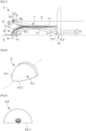
- the light device 2 essentially comprises a light source 4, a collector 6 capable of reflecting the light rays emitted by the light source to form a first light beam 12 along an optical axis 8 of the device, and a projection lens 10 of said beam .
- a projection lens 10 of said beam other systems projection optics as the projection lens are possible, such as in particular one or more mirrors.
- the light source 4 is advantageously of the semiconductor type, such as in particular an electroluminescent diode.
- the light source 4 emits light rays in a half-space delimited by the main plane of said source, according to the example shown, in a main direction perpendicular to said plane and to the optical axis 8.
- the direction main emission may be inclined relative to a direction perpendicular to the optical axis by an angle less than or equal to 25°.
- the collector 6 comprises a support 6.1, in the form of a shell or cap, and a reflecting surface 6.2 on the inner face of the support 6.1.
- the reflective surface 6.2 is advantageously of the profile of the elliptical or parabolic or “free form” type.
- the luminous device 2 also comprises a mirror 7 arranged in the extension of the reflecting surface 6.2 of the collector 6.
- the mirror 7 comprises a support 7.1 and a flat reflecting surface 7.2 formed on the support 7.1. The latter can be confused with or adjacent to the support 6.1 of the collector.
- the reflective surface 6.2 of the collector 6 is advantageously a surface of revolution around an axis parallel to the optical axis 8.
- the expression "parabolic type” generally applies to reflectors whose surface has a single focal point, that is to say a zone of convergence of the light rays such that the light rays emitted by a light source placed at the level of this convergence zone are projected at a great distance after reflection on the surface. Projected at a great distance means that these light rays do not converge on an area located at least 10 times the dimensions of the reflector.
- the reflected rays do not converge towards a convergence zone or, if they do converge, this convergence zone is located at a distance greater than or equal to 10 times the dimensions of the reflector.
- a parabolic-type surface may therefore have parabolic portions or not.
- a reflector having such a surface is generally used alone to create a light beam. Alternatively it can be used as a projection surface associated with an elliptical-type reflector. In this case the light source of the parabolic type reflector is the convergence zone of the rays reflected by the elliptical type reflector.
- the mirror 7, more particularly its flat reflective surface 7.2 is advantageously parallel to the optical axis 8. It can however be inclined with respect to said axis, for example by an angle less than or equal to 10°. If it is tilted, the mirror is advantageously divergent with the optical axis in the main direction of propagation of the light, that is to say from the light source 4 towards the projection lens 10.
- the collector 6 in the form of a shell or cap is advantageously made of materials having good heat resistance, for example glass or synthetic polymers such as polycarbonate PC or polyetherimide PEI.
- the light source 4 is placed at a focal point of the reflective surface 6.2 of the collector 6 so that its rays are collected and reflected towards the mirror 7.
- the latter forms a virtual image 6.2 of the reflective surface 6.2 and a virtual image 4 of the light source 4, shown in broken line at the figure 1 .
- the optical system 10 projects a light image of the virtual image 6.2 of the reflecting surface 6.2 and the virtual image 4 of the light source 4.
- At least some of these rays reflected by the mirror 7 have angles of inclination ⁇ relative to said axis, in a vertical plane, which are less than or equal to 25°, preferably less than or equal to 10°, so as to be under the so-called Gaussian conditions, making it possible to obtain a stigma, that is ie sharpness of the projected image.
- angles of inclination ⁇ relative to said axis, in a vertical plane which are less than or equal to 25°, preferably less than or equal to 10°, so as to be under the so-called Gaussian conditions, making it possible to obtain a stigma, that is ie sharpness of the projected image.
- the projection lens 10 has a first entry face 10.1 and exit face 10.2.
- the lens 10 is said to be thin, for example with a thickness along the optical axis which is less than 7 mm, in particular because of the low height of the lens and its long focal length.
- the lens 10 may have a focal point 10.3 advantageously located between the virtual light source and the virtual reflecting surface.
- the focus 10.3 in question is advantageously located on a zone 6.3 located between the virtual images 6.2 and 4 of the reflecting surface 6.2 and of the light source 4.
- the focus can be located on the virtual image 6.2 of the reflective surface 6.2, axially (that is to say along the optical axis) behind the virtual image 4 of the virtual light source 4.
- this focus it is also possible for this focus to be located at behind or in front of the virtual image of the reflective surface 6.2 of the collector 6 provided that it is close, preferably less than 10 mm, preferably less than 5 mm.
- the lens 10 is advantageously of the symmetrical convergent type with respect to the virtual optical axis 8 (in dashed line) located above the optical axis 8 and advantageously passing through the focal point 10.3.
- the reflective surface 6.2 of the collector 6, if it is of the elliptical type, has a second focus located at the front of the lens 10 and at a distance from the optical axis 8. It should be noted that it is also possible that this focal point is located at the rear of the lens and/or on the optical axis, provided that it is close to the lens, so as to reduce the width of the beam at the level of the entrance face of the lens.
- the light source 4 and the collector 6 are advantageously a first light source and a first collector, the device then possibly comprising a second light source 14 and a second collector 16 (shown in dashed lines).
- the second light source 14 and the second collector 16, forming a second light module are opposite with respect to the optical axis 8 More particularly, the first and second light sources 4 and 14 are on opposite faces of a common substrate through which the optical axis 8 passes.
- FIG. 2 is a rear view, in perspective, of a rear part of the collector 6 of the luminous device 2 of the figure 1 .
- the shape of the shell or cap of the support 6.1 as well as the fact that the reflecting surface 6.2 (not visible) has a rear edge 6.2.1.
- the plane in question comprises the rear edge 6.2.1. This extends laterally in the plane on either side of the axis of revolution.
- FIG. 3 is a representation of the light intensity at the reflective surface 6.2 of the collector seen from the outside, along the optical axis.
- This is the projected image of the virtual image of the reflective surface 6.2 of the collector, produced by the mirror 7 ( figure 1 ). More specifically, surface illuminance, ie the power of striking electromagnetic radiation per unit area perpendicular to its direction, expressed in W/m 2 .
- the dark zone covering the majority of the surface corresponds to weaker illuminations while the central, lighter zone corresponds to greater illuminations. It can be seen that the dark area is clearly delimited by the lower edge 6.2.1.
- the illuminated surface 6.2 naturally has a sharp lower edge capable of forming a cut in the projected lighting beam imaging this surface and also a light concentration force, in a central position at the height of the light source.
- FIG 4 is a graphic representation of the image projected by the light device of the figure 1 .
- the horizontal axis H and the vertical axis V intersect at the level of the optical axis of the light device.
- the curves are isolux, that is to say correspond to the zones of the light beam 12 which have the same illumination expressed in lux.
- the curves in the center correspond to a higher level of illumination than at the periphery.
- the light beam 12 has a lower horizontal cut-off, essentially at the level of the horizontal axis.
- the cut is not perfectly straight; it has a curvature which corresponds to aberrations of the image thus produced.
- the horizontal cut is made by the edge 6.2.1 ( picture 3 ) which is the trailing edge ( figure 2 ) of the reflective surface 6.2 of the collector 6.
- the focal point 10.3 of the lens 10 ( figure 1 ) is advantageously located close to this edge ( picture 3 ) on the virtual reflecting surface, that is to say behind the virtual image 4 of the (first) light source 4. It can also be observed that the light beam produced has a high concentration of light above above the horizontal axis H.
- This light beam 12 is thus particularly suitable for carrying out a lighting function of the “road” type (“high-beam” in English) in addition to a lighting function of the “code” type (“low-beam” in English). English).
- FIG 5 is a schematic representation of a variant of the luminous device 2 of the first embodiment of the invention, illustrated in figure 1 .
- This variant of differs from the figure 1 in that the components of the light device 2' are turned over by 180° with respect to the optical axis 8, all other things possibly being equal.
- the light beam produced 12' is shown in figure 6 which is to be compared to figure 4 .
- a reversal of the light image can be observed, namely with an upper horizontal cutoff and a strong concentration of light under and at the level of the horizontal axis.
- This light beam is particularly suitable for performing a lighting function of the “code” (“low-beam”) type.
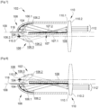
- FIG 7 is a schematic view of a light device according to a second embodiment of the invention.
- the reference numbers of the first embodiment are used to designate identical or corresponding elements, these numbers however being increased by 100. Reference is also made to the description of these elements within the framework of the first embodiment. Specific numbers between 100 and 200 are used to designate elements specific to this embodiment.
- This second embodiment differs from the first embodiment at the figure 1 essentially in that the mirror configured to form a virtual image of the light source and the reflecting surface is arranged differently, namely at the level of the optical axis 108 or at least close to it.
- the mirror 107 extends in fact along the optical axis 108, the latter being advantageously aligned with the support of the light source 104.
- the reflective surface 106.2 of the collector is configured to reflect towards the mirror the rays emitted by the source. light 104. These reflected rays correspond to virtual images 106.2 and 104 of the reflective surface 106.2 and of the light source 104, shown in broken lines.
- the light beam produced 112 will then correspond essentially to the light beam 12 of the first embodiment, illustrated in figure 4 .
- the lens 110 may have a focal point 110.3 advantageously located between the virtual light source and the virtual reflecting surface.
- the focal point 110.3 in question is advantageously located on a zone 106.3 located between the virtual image 106.2 of the reflecting surface 106.2 and the virtual image 104 of the light source 104.
- the focal point can be located on the virtual image 106.2 of the reflective surface 106.2, axially (that is to say along the optical axis) behind the virtual image 104 of the light source 104. It should be noted that it is also possible for this focus to be located at the rear or at the front of the virtual image 106.2 of the reflective surface 106.2 of the collector 106 provided that it is close, preferably less than 10 mm, preferably less than 5 mm.
- the mirror 107 more particularly its flat reflective surface 107.2 is advantageously parallel to the optical axis 108. It can however be inclined with respect to said axis, for example by an angle less than or equal to 10 °.
- the light source 104 and the collector 106 are advantageously a first light source and a first collector, the device then possibly comprising a second light source and a second collector.
- the first light source 104 and the first collector 106, on the one hand, and the second light source and the second collector, on the other hand, can be opposed with respect to the optical axis 8. Alternatively, they can be placed side by side.
- FIG 8 is a schematic representation of a variant of the light device 102 of the second embodiment of the invention illustrated in figure 7 .
- This variant differs from the figure 7 in that the components of the light device 102' are rotated 180° with respect to the optical axis 108, all other things being equal.
- the light beam produced 112' essentially corresponds to the light beam 12' produced by the light device of the figure 5 and illustrated at figure 6 .
- This is a light image reversed in relation to that of the light beam 112 produced by the light device of the figure 7 , essentially corresponding to that of the figure 4 , namely with an upper horizontal cut-off and a light concentration force under and at the level of the horizontal axis H.
- This light beam is particularly suitable for performing a “code” type (“low-beam” in English).
- the light devices which have just been described are particularly advantageous in that, by imaging the illuminated reflective surface, they make it possible to produce light beams with a concentration of light at a vertically off-center position. These beams are particularly useful for carrying out the “code” (“low-beam” in English) and “route” (“high-beam” in English) functions.
- these light devices through the use of a mirror, make it possible to turn over the light source and the collector associated with the light source, and thus accommodate bulk constraints.
Landscapes
- Engineering & Computer Science (AREA)
- General Engineering & Computer Science (AREA)
- Physics & Mathematics (AREA)
- Microelectronics & Electronic Packaging (AREA)
- Optics & Photonics (AREA)
- Mechanical Engineering (AREA)
- Non-Portable Lighting Devices Or Systems Thereof (AREA)
Applications Claiming Priority (2)
| Application Number | Priority Date | Filing Date | Title |
|---|---|---|---|
| FR1902615A FR3093788B1 (fr) | 2019-03-14 | 2019-03-14 | Dispositif lumineux imageant une surface eclairee virtuelle d’un collecteur |
| EP20158866.2A EP3708905B1 (de) | 2019-03-14 | 2020-02-21 | Beleuchtungsvorrichtung zur abbildung eines gespiegelten bilds eines kollektors |
Related Parent Applications (2)
| Application Number | Title | Priority Date | Filing Date |
|---|---|---|---|
| EP20158866.2A Division EP3708905B1 (de) | 2019-03-14 | 2020-02-21 | Beleuchtungsvorrichtung zur abbildung eines gespiegelten bilds eines kollektors |
| EP20158866.2A Division-Into EP3708905B1 (de) | 2019-03-14 | 2020-02-21 | Beleuchtungsvorrichtung zur abbildung eines gespiegelten bilds eines kollektors |
Publications (2)
| Publication Number | Publication Date |
|---|---|
| EP4134586A1 true EP4134586A1 (de) | 2023-02-15 |
| EP4134586B1 EP4134586B1 (de) | 2025-07-09 |
Family
ID=67383999
Family Applications (2)
| Application Number | Title | Priority Date | Filing Date |
|---|---|---|---|
| EP22198166.5A Active EP4134586B1 (de) | 2019-03-14 | 2020-02-21 | Beleuchtungsvorrichtung zur abbildung einer virtuellen beleuchteten oberfläche eines kollektors |
| EP20158866.2A Active EP3708905B1 (de) | 2019-03-14 | 2020-02-21 | Beleuchtungsvorrichtung zur abbildung eines gespiegelten bilds eines kollektors |
Family Applications After (1)
| Application Number | Title | Priority Date | Filing Date |
|---|---|---|---|
| EP20158866.2A Active EP3708905B1 (de) | 2019-03-14 | 2020-02-21 | Beleuchtungsvorrichtung zur abbildung eines gespiegelten bilds eines kollektors |
Country Status (8)
| Country | Link |
|---|---|
| US (1) | US10920949B2 (de) |
| EP (2) | EP4134586B1 (de) |
| JP (1) | JP7515276B2 (de) |
| KR (1) | KR102841256B1 (de) |
| CN (2) | CN119123352A (de) |
| ES (1) | ES3042294T3 (de) |
| FR (1) | FR3093788B1 (de) |
| PL (1) | PL3708905T3 (de) |
Families Citing this family (5)
| Publication number | Priority date | Publication date | Assignee | Title |
|---|---|---|---|---|
| EP3408138B1 (de) * | 2016-01-29 | 2022-11-23 | Gentex Corporation | Indikatoroptik für ein fahrzeugbeleuchtungsmodul |
| FR3084728B1 (fr) * | 2018-07-31 | 2021-03-19 | Valeo Vision | Module lumineux imageant la surface eclairee d'un collecteur |
| FR3118127B1 (fr) * | 2020-12-18 | 2022-12-16 | Valeo Vision | Dispositif lumineux bi-fonction avec lentille rotative |
| FR3130011B1 (fr) | 2021-12-07 | 2024-04-05 | Valeo Vision | Dispositif lumineux d’un véhicule automobile |
| US20250145081A1 (en) * | 2022-07-12 | 2025-05-08 | Muth Mirror Systems, Llc | Reflecting optic assembly |
Citations (6)
| Publication number | Priority date | Publication date | Assignee | Title |
|---|---|---|---|---|
| JP2007287522A (ja) * | 2006-04-18 | 2007-11-01 | Koito Mfg Co Ltd | 車両用前照灯の灯具ユニット |
| EP1857731A2 (de) * | 2006-05-17 | 2007-11-21 | Ichikoh Industries, Ltd. | Fahrzeugbeleuchtungsvorrichtung |
| JP2009259468A (ja) * | 2008-04-14 | 2009-11-05 | Ichikoh Ind Ltd | 車両用灯具 |
| US20160186954A1 (en) * | 2014-12-24 | 2016-06-30 | Sl Corporation | Low Beam Shield for Headlamps |
| FR3038695A1 (fr) * | 2015-07-10 | 2017-01-13 | Valeo Vision | Module lumineux pour l'eclairage et/ou la signalisation d'un vehicule automobile |
| FR3047541A1 (fr) | 2015-12-10 | 2017-08-11 | Valeo Vision | Module d'eclairage automobile avec fonctions code et route combinees et une source lumineuse ajustable |
Family Cites Families (26)
| Publication number | Priority date | Publication date | Assignee | Title |
|---|---|---|---|---|
| JPH02123605A (ja) * | 1988-11-01 | 1990-05-11 | Stanley Electric Co Ltd | 車両用信号灯具 |
| US5023758A (en) * | 1989-11-13 | 1991-06-11 | General Electric Company | Single arc discharge headlamp with light switch for high/low beam operation |
| FR2830073B1 (fr) * | 2001-09-27 | 2003-12-12 | Valeo Vision | Projecteur d'eclairage elliptique de vehicule automobile comportant un systeme optique secondaire |
| FR2839139B1 (fr) * | 2002-04-25 | 2005-01-14 | Valeo Vision | Module d'eclairage elliptique sans cache realisant un faisceau d'eclairage a coupure et projecteur comportant un tel module |
| JP2004349130A (ja) * | 2003-05-22 | 2004-12-09 | Koito Mfg Co Ltd | 車両用灯具 |
| FR2866411A1 (fr) * | 2004-02-13 | 2005-08-19 | Valeo Vision | Projecteur pour vehicule automobile comportant un reflecteur et un element de deviation optique |
| FR2858042B1 (fr) * | 2003-07-24 | 2005-09-23 | Valeo Vision | Module d'eclairage elliptique sans cache realisant un faisceau d'eclairage a coupure et projecteur comportant un tel module |
| JP4526256B2 (ja) * | 2003-10-17 | 2010-08-18 | スタンレー電気株式会社 | 光源モジュールおよび該光源モジュールを具備する灯具 |
| JP4108597B2 (ja) * | 2003-12-24 | 2008-06-25 | 株式会社小糸製作所 | 車両用灯具ユニット |
| JP4339143B2 (ja) * | 2004-02-10 | 2009-10-07 | 株式会社小糸製作所 | 車両用灯具ユニット |
| JP2008123753A (ja) * | 2006-11-09 | 2008-05-29 | Koito Mfg Co Ltd | 車両用灯具ユニット |
| JP5281359B2 (ja) * | 2008-10-30 | 2013-09-04 | 株式会社小糸製作所 | 車両用灯具ユニット及び車両用灯具 |
| FR2940403B1 (fr) * | 2008-12-19 | 2014-01-17 | Valeo Vision Sas | Dispositif d'eclairage pour projecteur de vehicule assurant plusieurs fonctions d'eclairage ou une fonction variable avec une seule source lumineuse |
| JP5423159B2 (ja) * | 2009-06-04 | 2014-02-19 | スタンレー電気株式会社 | 車両用灯具 |
| AT510454B1 (de) * | 2010-10-14 | 2013-04-15 | Zizala Lichtsysteme Gmbh | Led-fahrzeugscheinwerfer |
| JP2012160356A (ja) * | 2011-02-01 | 2012-08-23 | Stanley Electric Co Ltd | 車両用灯具 |
| DE102011013211B4 (de) * | 2011-03-05 | 2012-12-06 | Automotive Lighting Reutlingen Gmbh | Kraftfahrzeugscheinwerfer mit einem Mehrfunktions-Projektionsmodul |
| JP5640306B2 (ja) * | 2011-03-14 | 2014-12-17 | スタンレー電気株式会社 | 灯具ユニット |
| JP5879065B2 (ja) * | 2011-07-29 | 2016-03-08 | スタンレー電気株式会社 | 車両用前照灯 |
| JP5830294B2 (ja) * | 2011-07-29 | 2015-12-09 | スタンレー電気株式会社 | 車両用前照灯 |
| US8939627B2 (en) * | 2011-07-29 | 2015-01-27 | Stanley Electric Co., Ltd. | Vehicle lighting unit |
| DE102012202290B4 (de) * | 2012-02-15 | 2014-03-27 | Automotive Lighting Reutlingen Gmbh | Lichtmodul für ein blendungsfreies Kraftfahrzeug-Fernlicht |
| WO2013132530A1 (ja) * | 2012-03-06 | 2013-09-12 | 三菱電機株式会社 | 前照灯用光源および前照灯 |
| DE102013207845A1 (de) * | 2013-04-29 | 2014-10-30 | Automotive Lighting Reutlingen Gmbh | Lichtmodul für einen Kraftfahrzeugscheinwerfer |
| FR3039630A1 (fr) * | 2015-07-28 | 2017-02-03 | Valeo Vision | Systeme d'eclairage pour projecteur de vehicule automobile |
| FR3063795B1 (fr) * | 2017-03-13 | 2019-04-05 | Valeo Vision | Dispositif lumineux, notamment d'eclairage et/ou de signalisation, pour vehicule automobile |
-
2019
- 2019-03-14 FR FR1902615A patent/FR3093788B1/fr not_active Expired - Fee Related
-
2020
- 2020-02-21 PL PL20158866.2T patent/PL3708905T3/pl unknown
- 2020-02-21 ES ES22198166T patent/ES3042294T3/es active Active
- 2020-02-21 EP EP22198166.5A patent/EP4134586B1/de active Active
- 2020-02-21 EP EP20158866.2A patent/EP3708905B1/de active Active
- 2020-03-11 US US16/815,272 patent/US10920949B2/en active Active
- 2020-03-12 KR KR1020200030690A patent/KR102841256B1/ko active Active
- 2020-03-13 JP JP2020044463A patent/JP7515276B2/ja active Active
- 2020-03-13 CN CN202410787963.4A patent/CN119123352A/zh active Pending
- 2020-03-13 CN CN202010176786.8A patent/CN111692568B/zh active Active
Patent Citations (6)
| Publication number | Priority date | Publication date | Assignee | Title |
|---|---|---|---|---|
| JP2007287522A (ja) * | 2006-04-18 | 2007-11-01 | Koito Mfg Co Ltd | 車両用前照灯の灯具ユニット |
| EP1857731A2 (de) * | 2006-05-17 | 2007-11-21 | Ichikoh Industries, Ltd. | Fahrzeugbeleuchtungsvorrichtung |
| JP2009259468A (ja) * | 2008-04-14 | 2009-11-05 | Ichikoh Ind Ltd | 車両用灯具 |
| US20160186954A1 (en) * | 2014-12-24 | 2016-06-30 | Sl Corporation | Low Beam Shield for Headlamps |
| FR3038695A1 (fr) * | 2015-07-10 | 2017-01-13 | Valeo Vision | Module lumineux pour l'eclairage et/ou la signalisation d'un vehicule automobile |
| FR3047541A1 (fr) | 2015-12-10 | 2017-08-11 | Valeo Vision | Module d'eclairage automobile avec fonctions code et route combinees et une source lumineuse ajustable |
Also Published As
| Publication number | Publication date |
|---|---|
| FR3093788B1 (fr) | 2022-05-27 |
| CN111692568A (zh) | 2020-09-22 |
| KR102841256B1 (ko) | 2025-07-31 |
| EP4134586B1 (de) | 2025-07-09 |
| JP2020149976A (ja) | 2020-09-17 |
| ES3042294T3 (en) | 2025-11-19 |
| EP3708905A1 (de) | 2020-09-16 |
| JP7515276B2 (ja) | 2024-07-12 |
| EP3708905B1 (de) | 2022-11-09 |
| FR3093788A1 (fr) | 2020-09-18 |
| US20200292144A1 (en) | 2020-09-17 |
| US10920949B2 (en) | 2021-02-16 |
| CN111692568B (zh) | 2024-07-05 |
| KR20200110215A (ko) | 2020-09-23 |
| PL3708905T3 (pl) | 2023-03-13 |
| CN119123352A (zh) | 2024-12-13 |
Similar Documents
| Publication | Publication Date | Title |
|---|---|---|
| EP3708904B1 (de) | Leuchtvorrichtung, die die beleuchteten flächen von mindestens zwei kollektoren abbildet | |
| EP3708905B1 (de) | Beleuchtungsvorrichtung zur abbildung eines gespiegelten bilds eines kollektors | |
| WO2020025171A1 (fr) | Module lumineux imageant la surface eclairee d'un collecteur | |
| EP2743567B1 (de) | Optisches hauptelement, beleuchtungsmodul und scheinwerfer für kraftfahrzeug | |
| EP4062098B1 (de) | Kombiniertes leuchtmodul zur abbildung der beleuchteten fläche eines kollektors | |
| FR3047541B1 (fr) | Module d'eclairage automobile avec fonctions code et route combinees et une source lumineuse ajustable | |
| EP1528312B1 (de) | Beleuchtungsmodul für Kfz-Scheinwerfer | |
| EP3167226B1 (de) | Beleuchtungsmodul für ein kraftfahrzeug | |
| EP1500869A1 (de) | Elliptische Beleuchtungseinheit ohne Lichtblende zur Erzeugung eines Abblendlichtbündels und Scheinwerfer mit einer derartigen Belleuchtungseinheit | |
| EP1857732A1 (de) | Vorrichtung zur Beleuchtung und/oder Signalisierung für Kraftfahrzeuge | |
| EP3521692B1 (de) | Bifunktions-leuchtmodul mit gemeinsamer beleuchteter fläche | |
| EP3002504A2 (de) | Leuchtmodul zur beleuchtung und/oder signalisierung für kraftfahrzeug | |
| FR3118120A1 (fr) | Projecteur automobile avec plusieurs modules d’éclairage sur une platine commune inclinée. | |
| EP4051954B1 (de) | Zwischen links- und rechtslenker verstellbarer automobilscheinwerfer | |
| WO2022129420A1 (fr) | Module lumineux imageant la surface eclairee d'un collecteur avec bloqueur de rayons parasites | |
| WO2022162180A1 (fr) | Dispositif d'éclairage de la route d'un véhicule automobile | |
| EP4264123B1 (de) | Beleuchtungsvorrichtung mit doppelfunktion und rotierender linse | |
| EP4569262A1 (de) | Scheinwerfer mit vertikaler hell-dunkel-grenze und verlängerung für ein kraftfahrzeug | |
| EP3575675B1 (de) | Beleuchtungsmodul zur erzeugung einer hell-dunkel-grenze mit einem "zwei zonen" reflektor | |
| FR3133901A1 (fr) | Module lumineux imageant la surface éclairée d’un collecteur avec bloqueur de rayons parasites extrudé |
Legal Events
| Date | Code | Title | Description |
|---|---|---|---|
| PUAI | Public reference made under article 153(3) epc to a published international application that has entered the european phase |
Free format text: ORIGINAL CODE: 0009012 |
|
| STAA | Information on the status of an ep patent application or granted ep patent |
Free format text: STATUS: THE APPLICATION HAS BEEN PUBLISHED |
|
| AC | Divisional application: reference to earlier application |
Ref document number: 3708905 Country of ref document: EP Kind code of ref document: P |
|
| AK | Designated contracting states |
Kind code of ref document: A1 Designated state(s): AL AT BE BG CH CY CZ DE DK EE ES FI FR GB GR HR HU IE IS IT LI LT LU LV MC MK MT NL NO PL PT RO RS SE SI SK SM TR |
|
| STAA | Information on the status of an ep patent application or granted ep patent |
Free format text: STATUS: REQUEST FOR EXAMINATION WAS MADE |
|
| 17P | Request for examination filed |
Effective date: 20231114 |
|
| RBV | Designated contracting states (corrected) |
Designated state(s): AL AT BE BG CH CY CZ DE DK EE ES FI FR GB GR HR HU IE IS IT LI LT LU LV MC MK MT NL NO PL PT RO RS SE SI SK SM TR |
|
| GRAP | Despatch of communication of intention to grant a patent |
Free format text: ORIGINAL CODE: EPIDOSNIGR1 |
|
| STAA | Information on the status of an ep patent application or granted ep patent |
Free format text: STATUS: GRANT OF PATENT IS INTENDED |
|
| RIC1 | Information provided on ipc code assigned before grant |
Ipc: F21S 41/25 20180101ALI20250116BHEP Ipc: F21S 41/32 20180101ALI20250116BHEP Ipc: F21S 41/365 20180101ALI20250116BHEP Ipc: F21S 41/255 20180101ALI20250116BHEP Ipc: F21S 41/148 20180101ALI20250116BHEP Ipc: F21S 41/147 20180101ALI20250116BHEP Ipc: F21S 41/33 20180101AFI20250116BHEP |
|
| INTG | Intention to grant announced |
Effective date: 20250203 |
|
| GRAS | Grant fee paid |
Free format text: ORIGINAL CODE: EPIDOSNIGR3 |
|
| GRAA | (expected) grant |
Free format text: ORIGINAL CODE: 0009210 |
|
| STAA | Information on the status of an ep patent application or granted ep patent |
Free format text: STATUS: THE PATENT HAS BEEN GRANTED |
|
| AC | Divisional application: reference to earlier application |
Ref document number: 3708905 Country of ref document: EP Kind code of ref document: P |
|
| AK | Designated contracting states |
Kind code of ref document: B1 Designated state(s): AL AT BE BG CH CY CZ DE DK EE ES FI FR GB GR HR HU IE IS IT LI LT LU LV MC MK MT NL NO PL PT RO RS SE SI SK SM TR |
|
| REG | Reference to a national code |
Ref country code: GB Ref legal event code: FG4D Free format text: NOT ENGLISH |
|
| REG | Reference to a national code |
Ref country code: CH Ref legal event code: EP |
|
| REG | Reference to a national code |
Ref country code: IE Ref legal event code: FG4D Free format text: LANGUAGE OF EP DOCUMENT: FRENCH |
|
| REG | Reference to a national code |
Ref country code: DE Ref legal event code: R096 Ref document number: 602020054443 Country of ref document: DE |
|
| REG | Reference to a national code |
Ref country code: NL Ref legal event code: MP Effective date: 20250709 |
|
| REG | Reference to a national code |
Ref country code: ES Ref legal event code: FG2A Ref document number: 3042294 Country of ref document: ES Kind code of ref document: T3 Effective date: 20251119 |
|
| PG25 | Lapsed in a contracting state [announced via postgrant information from national office to epo] |
Ref country code: PT Free format text: LAPSE BECAUSE OF FAILURE TO SUBMIT A TRANSLATION OF THE DESCRIPTION OR TO PAY THE FEE WITHIN THE PRESCRIBED TIME-LIMIT Effective date: 20251110 |
|
| PG25 | Lapsed in a contracting state [announced via postgrant information from national office to epo] |
Ref country code: NL Free format text: LAPSE BECAUSE OF FAILURE TO SUBMIT A TRANSLATION OF THE DESCRIPTION OR TO PAY THE FEE WITHIN THE PRESCRIBED TIME-LIMIT Effective date: 20250709 |
|
| PG25 | Lapsed in a contracting state [announced via postgrant information from national office to epo] |
Ref country code: IS Free format text: LAPSE BECAUSE OF FAILURE TO SUBMIT A TRANSLATION OF THE DESCRIPTION OR TO PAY THE FEE WITHIN THE PRESCRIBED TIME-LIMIT Effective date: 20251109 |
|
| PG25 | Lapsed in a contracting state [announced via postgrant information from national office to epo] |
Ref country code: NO Free format text: LAPSE BECAUSE OF FAILURE TO SUBMIT A TRANSLATION OF THE DESCRIPTION OR TO PAY THE FEE WITHIN THE PRESCRIBED TIME-LIMIT Effective date: 20251009 |
|
| REG | Reference to a national code |
Ref country code: LT Ref legal event code: MG9D |
|
| PG25 | Lapsed in a contracting state [announced via postgrant information from national office to epo] |
Ref country code: FI Free format text: LAPSE BECAUSE OF FAILURE TO SUBMIT A TRANSLATION OF THE DESCRIPTION OR TO PAY THE FEE WITHIN THE PRESCRIBED TIME-LIMIT Effective date: 20250709 |
|
| PG25 | Lapsed in a contracting state [announced via postgrant information from national office to epo] |
Ref country code: HR Free format text: LAPSE BECAUSE OF FAILURE TO SUBMIT A TRANSLATION OF THE DESCRIPTION OR TO PAY THE FEE WITHIN THE PRESCRIBED TIME-LIMIT Effective date: 20250709 |
|
| PG25 | Lapsed in a contracting state [announced via postgrant information from national office to epo] |
Ref country code: GR Free format text: LAPSE BECAUSE OF FAILURE TO SUBMIT A TRANSLATION OF THE DESCRIPTION OR TO PAY THE FEE WITHIN THE PRESCRIBED TIME-LIMIT Effective date: 20251010 |
|
| PG25 | Lapsed in a contracting state [announced via postgrant information from national office to epo] |
Ref country code: SE Free format text: LAPSE BECAUSE OF FAILURE TO SUBMIT A TRANSLATION OF THE DESCRIPTION OR TO PAY THE FEE WITHIN THE PRESCRIBED TIME-LIMIT Effective date: 20250709 |
|
| PG25 | Lapsed in a contracting state [announced via postgrant information from national office to epo] |
Ref country code: LV Free format text: LAPSE BECAUSE OF FAILURE TO SUBMIT A TRANSLATION OF THE DESCRIPTION OR TO PAY THE FEE WITHIN THE PRESCRIBED TIME-LIMIT Effective date: 20250709 |
|
| PG25 | Lapsed in a contracting state [announced via postgrant information from national office to epo] |
Ref country code: BG Free format text: LAPSE BECAUSE OF FAILURE TO SUBMIT A TRANSLATION OF THE DESCRIPTION OR TO PAY THE FEE WITHIN THE PRESCRIBED TIME-LIMIT Effective date: 20250709 |
|
| PG25 | Lapsed in a contracting state [announced via postgrant information from national office to epo] |
Ref country code: RS Free format text: LAPSE BECAUSE OF FAILURE TO SUBMIT A TRANSLATION OF THE DESCRIPTION OR TO PAY THE FEE WITHIN THE PRESCRIBED TIME-LIMIT Effective date: 20251009 |
|
| PG25 | Lapsed in a contracting state [announced via postgrant information from national office to epo] |
Ref country code: SM Free format text: LAPSE BECAUSE OF FAILURE TO SUBMIT A TRANSLATION OF THE DESCRIPTION OR TO PAY THE FEE WITHIN THE PRESCRIBED TIME-LIMIT Effective date: 20250709 |
|
| PGFP | Annual fee paid to national office [announced via postgrant information from national office to epo] |
Ref country code: GB Payment date: 20260219 Year of fee payment: 7 |
|
| PGFP | Annual fee paid to national office [announced via postgrant information from national office to epo] |
Ref country code: ES Payment date: 20260309 Year of fee payment: 7 |
|
| PG25 | Lapsed in a contracting state [announced via postgrant information from national office to epo] |
Ref country code: DK Free format text: LAPSE BECAUSE OF FAILURE TO SUBMIT A TRANSLATION OF THE DESCRIPTION OR TO PAY THE FEE WITHIN THE PRESCRIBED TIME-LIMIT Effective date: 20250709 |
|
| PGFP | Annual fee paid to national office [announced via postgrant information from national office to epo] |
Ref country code: DE Payment date: 20260206 Year of fee payment: 7 |
|
| PGFP | Annual fee paid to national office [announced via postgrant information from national office to epo] |
Ref country code: AT Payment date: 20260120 Year of fee payment: 7 |
|
| PG25 | Lapsed in a contracting state [announced via postgrant information from national office to epo] |
Ref country code: IT Free format text: LAPSE BECAUSE OF FAILURE TO SUBMIT A TRANSLATION OF THE DESCRIPTION OR TO PAY THE FEE WITHIN THE PRESCRIBED TIME-LIMIT Effective date: 20250709 |
|
| PGFP | Annual fee paid to national office [announced via postgrant information from national office to epo] |
Ref country code: FR Payment date: 20260227 Year of fee payment: 7 |
|
| PGFP | Annual fee paid to national office [announced via postgrant information from national office to epo] |
Ref country code: CZ Payment date: 20260130 Year of fee payment: 7 |
|
| PGFP | Annual fee paid to national office [announced via postgrant information from national office to epo] |
Ref country code: PL Payment date: 20260119 Year of fee payment: 7 |
|
| PG25 | Lapsed in a contracting state [announced via postgrant information from national office to epo] |
Ref country code: EE Free format text: LAPSE BECAUSE OF FAILURE TO SUBMIT A TRANSLATION OF THE DESCRIPTION OR TO PAY THE FEE WITHIN THE PRESCRIBED TIME-LIMIT Effective date: 20250709 Ref country code: SK Free format text: LAPSE BECAUSE OF FAILURE TO SUBMIT A TRANSLATION OF THE DESCRIPTION OR TO PAY THE FEE WITHIN THE PRESCRIBED TIME-LIMIT Effective date: 20250709 |