EP4137725A1 - Clapet antiretour et système de frein comprenant celui-ci - Google Patents
Clapet antiretour et système de frein comprenant celui-ci Download PDFInfo
- Publication number
- EP4137725A1 EP4137725A1 EP21789176.1A EP21789176A EP4137725A1 EP 4137725 A1 EP4137725 A1 EP 4137725A1 EP 21789176 A EP21789176 A EP 21789176A EP 4137725 A1 EP4137725 A1 EP 4137725A1
- Authority
- EP
- European Patent Office
- Prior art keywords
- valve
- hydraulic
- flow path
- housing
- check valve
- Prior art date
- Legal status (The legal status is an assumption and is not a legal conclusion. Google has not performed a legal analysis and makes no representation as to the accuracy of the status listed.)
- Pending
Links
Images


Classifications
-
- F—MECHANICAL ENGINEERING; LIGHTING; HEATING; WEAPONS; BLASTING
- F16—ENGINEERING ELEMENTS AND UNITS; GENERAL MEASURES FOR PRODUCING AND MAINTAINING EFFECTIVE FUNCTIONING OF MACHINES OR INSTALLATIONS; THERMAL INSULATION IN GENERAL
- F16K—VALVES; TAPS; COCKS; ACTUATING-FLOATS; DEVICES FOR VENTING OR AERATING
- F16K15/00—Check valves
- F16K15/02—Check valves with guided rigid valve members
- F16K15/04—Check valves with guided rigid valve members shaped as balls
- F16K15/042—Check valves with guided rigid valve members shaped as balls with a plurality of balls
-
- B—PERFORMING OPERATIONS; TRANSPORTING
- B60—VEHICLES IN GENERAL
- B60T—VEHICLE BRAKE CONTROL SYSTEMS OR PARTS THEREOF; BRAKE CONTROL SYSTEMS OR PARTS THEREOF, IN GENERAL; ARRANGEMENT OF BRAKING ELEMENTS ON VEHICLES IN GENERAL; PORTABLE DEVICES FOR PREVENTING UNWANTED MOVEMENT OF VEHICLES; VEHICLE MODIFICATIONS TO FACILITATE COOLING OF BRAKES
- B60T13/00—Transmitting braking action from initiating means to ultimate brake actuator with power assistance or drive; Brake systems incorporating such transmitting means, e.g. air-pressure brake systems
- B60T13/10—Transmitting braking action from initiating means to ultimate brake actuator with power assistance or drive; Brake systems incorporating such transmitting means, e.g. air-pressure brake systems with fluid assistance, drive, or release
- B60T13/12—Transmitting braking action from initiating means to ultimate brake actuator with power assistance or drive; Brake systems incorporating such transmitting means, e.g. air-pressure brake systems with fluid assistance, drive, or release the fluid being liquid
- B60T13/14—Transmitting braking action from initiating means to ultimate brake actuator with power assistance or drive; Brake systems incorporating such transmitting means, e.g. air-pressure brake systems with fluid assistance, drive, or release the fluid being liquid using accumulators or reservoirs fed by pumps
- B60T13/142—Systems with master cylinder
-
- B—PERFORMING OPERATIONS; TRANSPORTING
- B60—VEHICLES IN GENERAL
- B60T—VEHICLE BRAKE CONTROL SYSTEMS OR PARTS THEREOF; BRAKE CONTROL SYSTEMS OR PARTS THEREOF, IN GENERAL; ARRANGEMENT OF BRAKING ELEMENTS ON VEHICLES IN GENERAL; PORTABLE DEVICES FOR PREVENTING UNWANTED MOVEMENT OF VEHICLES; VEHICLE MODIFICATIONS TO FACILITATE COOLING OF BRAKES
- B60T13/00—Transmitting braking action from initiating means to ultimate brake actuator with power assistance or drive; Brake systems incorporating such transmitting means, e.g. air-pressure brake systems
- B60T13/10—Transmitting braking action from initiating means to ultimate brake actuator with power assistance or drive; Brake systems incorporating such transmitting means, e.g. air-pressure brake systems with fluid assistance, drive, or release
- B60T13/66—Electrical control in fluid-pressure brake systems
- B60T13/68—Electrical control in fluid-pressure brake systems by electrically-controlled valves
- B60T13/686—Electrical control in fluid-pressure brake systems by electrically-controlled valves in hydraulic systems or parts thereof
-
- B—PERFORMING OPERATIONS; TRANSPORTING
- B60—VEHICLES IN GENERAL
- B60T—VEHICLE BRAKE CONTROL SYSTEMS OR PARTS THEREOF; BRAKE CONTROL SYSTEMS OR PARTS THEREOF, IN GENERAL; ARRANGEMENT OF BRAKING ELEMENTS ON VEHICLES IN GENERAL; PORTABLE DEVICES FOR PREVENTING UNWANTED MOVEMENT OF VEHICLES; VEHICLE MODIFICATIONS TO FACILITATE COOLING OF BRAKES
- B60T15/00—Construction arrangement, or operation of valves incorporated in power brake systems and not covered by groups B60T11/00 or B60T13/00
- B60T15/02—Application and release valves
- B60T15/025—Electrically controlled valves
- B60T15/028—Electrically controlled valves in hydraulic systems
-
- F—MECHANICAL ENGINEERING; LIGHTING; HEATING; WEAPONS; BLASTING
- F16—ENGINEERING ELEMENTS AND UNITS; GENERAL MEASURES FOR PRODUCING AND MAINTAINING EFFECTIVE FUNCTIONING OF MACHINES OR INSTALLATIONS; THERMAL INSULATION IN GENERAL
- F16K—VALVES; TAPS; COCKS; ACTUATING-FLOATS; DEVICES FOR VENTING OR AERATING
- F16K11/00—Multiple-way valves, e.g. mixing valves; Pipe fittings incorporating such valves
- F16K11/10—Multiple-way valves, e.g. mixing valves; Pipe fittings incorporating such valves with two or more closure members not moving as a unit
- F16K11/105—Three-way check or safety valves with two or more closure members
-
- F—MECHANICAL ENGINEERING; LIGHTING; HEATING; WEAPONS; BLASTING
- F16—ENGINEERING ELEMENTS AND UNITS; GENERAL MEASURES FOR PRODUCING AND MAINTAINING EFFECTIVE FUNCTIONING OF MACHINES OR INSTALLATIONS; THERMAL INSULATION IN GENERAL
- F16K—VALVES; TAPS; COCKS; ACTUATING-FLOATS; DEVICES FOR VENTING OR AERATING
- F16K15/00—Check valves
- F16K15/02—Check valves with guided rigid valve members
- F16K15/04—Check valves with guided rigid valve members shaped as balls
- F16K15/044—Check valves with guided rigid valve members shaped as balls spring-loaded
-
- F—MECHANICAL ENGINEERING; LIGHTING; HEATING; WEAPONS; BLASTING
- F16—ENGINEERING ELEMENTS AND UNITS; GENERAL MEASURES FOR PRODUCING AND MAINTAINING EFFECTIVE FUNCTIONING OF MACHINES OR INSTALLATIONS; THERMAL INSULATION IN GENERAL
- F16K—VALVES; TAPS; COCKS; ACTUATING-FLOATS; DEVICES FOR VENTING OR AERATING
- F16K27/00—Construction of housing; Use of materials therefor
- F16K27/02—Construction of housing; Use of materials therefor of lift valves
- F16K27/0209—Check valves or pivoted valves
-
- B—PERFORMING OPERATIONS; TRANSPORTING
- B60—VEHICLES IN GENERAL
- B60T—VEHICLE BRAKE CONTROL SYSTEMS OR PARTS THEREOF; BRAKE CONTROL SYSTEMS OR PARTS THEREOF, IN GENERAL; ARRANGEMENT OF BRAKING ELEMENTS ON VEHICLES IN GENERAL; PORTABLE DEVICES FOR PREVENTING UNWANTED MOVEMENT OF VEHICLES; VEHICLE MODIFICATIONS TO FACILITATE COOLING OF BRAKES
- B60T2270/00—Further aspects of brake control systems not otherwise provided for
- B60T2270/40—Failsafe aspects of brake control systems
- B60T2270/402—Back-up
-
- B—PERFORMING OPERATIONS; TRANSPORTING
- B60—VEHICLES IN GENERAL
- B60T—VEHICLE BRAKE CONTROL SYSTEMS OR PARTS THEREOF; BRAKE CONTROL SYSTEMS OR PARTS THEREOF, IN GENERAL; ARRANGEMENT OF BRAKING ELEMENTS ON VEHICLES IN GENERAL; PORTABLE DEVICES FOR PREVENTING UNWANTED MOVEMENT OF VEHICLES; VEHICLE MODIFICATIONS TO FACILITATE COOLING OF BRAKES
- B60T2270/00—Further aspects of brake control systems not otherwise provided for
- B60T2270/40—Failsafe aspects of brake control systems
- B60T2270/404—Brake-by-wire or X-by-wire failsafe
-
- B—PERFORMING OPERATIONS; TRANSPORTING
- B60—VEHICLES IN GENERAL
- B60T—VEHICLE BRAKE CONTROL SYSTEMS OR PARTS THEREOF; BRAKE CONTROL SYSTEMS OR PARTS THEREOF, IN GENERAL; ARRANGEMENT OF BRAKING ELEMENTS ON VEHICLES IN GENERAL; PORTABLE DEVICES FOR PREVENTING UNWANTED MOVEMENT OF VEHICLES; VEHICLE MODIFICATIONS TO FACILITATE COOLING OF BRAKES
- B60T2270/00—Further aspects of brake control systems not otherwise provided for
- B60T2270/82—Brake-by-Wire, EHB
Definitions
- the present invention relates to a check valve and a brake system, and more particularly, to a check valve used in a brake system of a vehicle and a brake system including the same.
- a brake system is generally intended to efficiently prevent a slip phenomenon of a wheel which may occur during braking, sudden starting or sudden acceleration of a vehicle.
- a brake system includes a plurality of solenoid valves for controlling a braking hydraulic pressure transmitted from a master cylinder to a wheel cylinder side, and a number of check valves for preventing a reverse flow of oil, which are installed in a modulator block in which a flow path of a hydraulic circuit is formed and which operate in accordance with a braking hydraulic pressure.
- Conventional brake systems supply a required brake pressure to a wheel cylinder by means of a vacuum booster when a driver depresses a brake pedal.
- an electronic brake system has been used, in which a driver's braking intention is transmitted as an electrical signal from a pedal displacement sensor that senses a displacement of a brake pedal when the driver depresses the brake pedal, and a hydraulic pressure supply device that supplies a brake pressure to a wheel cylinder based on the received signal is provided.
- an electronic brake system includes Korean Patent Publication No. 10-2013-0092045 .
- an electronic brake system provided with a hydraulic pressure supply device operates a motor in accordance with a tread force of a brake pedal to generate a brake pressure.
- the braking pressure is generated by converting the rotational force of the motor into a linear motion and pressing a piston.
- a plurality of check valves are provided at various positions in a flow path formed in a modulator block.
- the check valves may be provided in a flow path connecting a hydraulic pressure supply device and a reservoir, a distribution flow path of a wheel cylinder, a simulator connection flow path, or the like.
- a check valve is assembled in the shape of a single component while including a valve housing, a ball provided in the valve housing to open and close a flow path, an elastic member that elastically supports the ball, a retainer or a plug member that prevents the elastic member from being detached, and the like.
- the check valve is then installed on a brake system so that oil flows only in one direction.
- a conventional check valve is not easy to manufacture because each component has to be manufactured through a process forming and a press scheme, and thus the manufacturing cost is high.
- a plurality of check valves provided in a modulator block of a vehicle are each provided in the shape of a single component, it is necessary not only to secure holes in the modulator block by the number of check valves when applied to a brake system, but also to independently connect peripheral flow paths.
- a brake system requires as much space for assembly as the number of check valves installed, which in turn increases the size of the product and adversely affects automotive parts where size and weight are important.
- a check valve which is in a simplified structure and in which a plurality of valve parts are integrally formed and a brake system including the check valve are provided.
- a check valve including a plurality of valve parts in which an internal flow path is selectively open/closed by an opening/closing member, the plurality of valve parts being stacked in a line.
- valve housing may further include a cylinder-shaped valve housing open on one side, wherein each opening/closing member of the plurality of valve parts is received from the open one side of the valve housing.
- valve housing may include a housing body that is stepped along a longitudinal direction and sequentially receives the opening/closing members, and a housing cap that is engaged with the housing body.
- the housing body may include a first body and a second body longitudinally engaged with the first body, the first and second bodies each including at least one valve part.
- first body and the second body may each include a body hole in which the opening/closing members selectively contact by a pressure of fluid.
- valve housing may include a plurality of body holes communicating between the inside and the outside, and each opening/closing member of the plurality of valve parts is provided between two adjacent body holes.
- each valve part of the plurality of valve parts may further include a valve seat including an orifice through which fluid passes, an elastic member elastically supporting one side of the opening/closing members which is selectively in contact with the orifice, and a filter cap engaged with the valve seat to receive the opening/closing members and supporting the other side of the elastic member.
- valve seat of another adjacent valve part may be engaged with a filter cap of any one of the plurality of valve parts.
- each opening/closing member of the plurality of valve parts may be arranged in the valve housing so as to pass fluid in one direction.
- valve housing may include a first body hole communicating between the inside and the outside, a second body hole, a third body hole, and a fourth body hole
- the plurality of valve parts may include a first valve part provided between the first and second body holes of the valve housing, a second valve part disposed between the second and third body holes, and a third valve part formed between the third and fourth body holes.
- first valve part, the second valve part, and the third valve part may be arranged in the valve housing so as to pass fluid in one direction.
- first valve part to the third valve part may each further include a valve seat having an orifice through which fluid passes, an elastic member for elastically supporting one side of the opening/closing members in selective contact with the orifice, and a filter cap for receiving the opening/closing members by being engaged with the valve seat and supporting the other side of the elastic member, and a valve seat of the adjacent second valve part may be engaged with the filter cap of the first valve part.
- valve housing may include a housing body provided in a cylindrical shape with one side open, and a housing cap engaged with the housing body with the first to third valve parts received in the open one side, the housing member may include a first body and a second body separated in a longitudinal direction, one of the first and second bodies may include the first valve part, and the other may include the second valve part and the third valve part.
- the first body may include a first body hole as an orifice with which an opening/closing member of the first valve part selectively comes into contact
- the second body may include a second body hole as an orifice with which an opening/closing member of the second valve part selectively comes into contact
- the third valve may include a valve seat provided with an orifice with which an opening/closing member selectively comes into contact.
- opening/closing members provided in at least one of the plurality of valve parts may be provided in the shape of a lip seal.
- At least one valve part of the plurality of valve parts may include a valve seat comprising a small diameter head, a large diameter flange, and a small diameter valve body; and a filter cap engaged with the valve body, wherein the opening/closing members in the form of a lip seal are fitted into the valve member of the valve seat and are positioned between the flange and the filter cap.
- opening/closing members provided in at least one of the plurality of valve parts may be provided in a ball shape.
- a brake system including: a check valve which is provided according to claim 1; a reservoir in which a pressurizing medium is stored; a master cylinder which is connected to the reservoir, the master cylinder having a master chamber and a master piston for discharging the pressurizing medium in response to a tread force of a brake pedal; a hydraulic pressure supply device which operates by an electrical signal to generate a hydraulic pressure; and a hydraulic control unit which has a first hydraulic circuit and a second hydraulic circuit to transmit the hydraulic pressure discharged from the hydraulic pressure supply device to wheel cylinders provided on two wheels, respectively, wherein the check valve is installed in a flow path connecting the hydraulic pressure supply device and the hydraulic control unit, and selectively transmits the hydraulic pressure of the hydraulic pressure supply device to the first hydraulic circuit or the second hydraulic circuit.
- a check valve and a brake system including the check valve according to an embodiment of the present invention may greatly improve the mass productivity of products because a plurality of valve parts are assembled in a single valve housing, thereby reducing the manufacturing cost due to a reduction in the number of parts and facilitating the assembly operation.
- a check valve and a brake system including the same simplify the structure of a valve part, the same may be manufactured by forging, which is a low cost method, and may reduce the component cost, and when applied to a vehicle, it is possible to solve the installation space constraints of the check valve and a flow path in a modular block, thereby improving the design freedom.
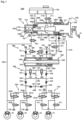
- FIG. 1 is a hydraulic circuit diagram showing an electronic brake system 1000 in which a check valve according to a first embodiment of the present invention is used.
- an electronic brake system 1000 includes: a reservoir 1100 in which a pressurizing medium is stored; an integrated master cylinder 1200 that provides a reaction force according to the pedal effort of a brake pedal 10 to ad river and pressurizes and discharges a pressurizing medium such as brake oil received inside; a hydraulic pressure supply device 1300 that receives the driver's braking intention as an electrical signal by a pedal displacement sensor that detects the displacement of the brake pedal 10 and generates hydraulic pressure of the pressurizing medium through a mechanical operation; a hydraulic control unit 1400 for controlling the hydraulic pressure provided from a hydraulic pressure supply device 1300; hydraulic circuits 1510, 1520 having a wheel cylinder 20 for braking each wheel (RR, RL, FR, and FL) by transferring the hydraulic pressure of the pressurizing medium; a dump control unit 1800 provided between the hydraulic pressure supply device 1300 and the reservoir 1100 to control the flow of the pressurizing medium; backup flow paths 1610, 1620 hydraulically connecting the
- the integrated master cylinder 1200 is provided so that, when the driver applies a tread force to the brake pedal 10 for braking operation, the driver provides a reaction force thereto to provide a stable pedal feel, and at the same time, the brake pedal 10 is actuated to pressurize and discharge the pressurizing medium contained therein.
- the highly integrated master cylinder 1200 may be arranged coaxially in one cylinder body 1210 with a simulation unit for supplying the driver with a pedal feel and a master cylinder unit for pressurizing and discharging the pressurizing medium received inside by the pedal depression force.
- an integrated master cylinder 1200 may include a cylinder body 1210 that has a chamber formed at the inside, a first master chamber 1220a that is formed on the inlet side of the cylinder body 1210 to which a brake pedal 10 is connected, a first master piston 1220 that is provided in the first master chambers 1220a and is displaceably provided by actuation of the brake pedal 10, a second master piston 1230 that is disposed on a second master chamber 1230a on the inner side or on the front side (left side with reference to FIG. 1 ) of the first master pistons 1220, and a pedal simulator 1240 that provides a pedal sensation through an elastic restoring force that occurs during compression and is disposed between the first master piston 1220 and the second master piston 1230.
- a first master chamber 1220a and a second master chamber 1230a may be formed sequentially from the brake pedal 10 side (right side with reference to FIG. 1 ) to the inner side (left side with reference to FIG. 1 ), on a cylinder body 1210 of an integrated master cylinder 1200.
- the first master piston 1220 and the second master piston 1230 are provided in each of the first and second master chambers 1220a, 1230a, and may form a hydraulic pressure or a negative pressure in the pressurizing medium received in each chamber according to the forward and backward movements.
- the cylinder body 1210 may include a large-diameter portion 1211 in which the first master chamber 1220a is formed, and the inner diameter thereof is relatively large, and a small-diameter portion 1212 in which the second master chamber 1230a is formed.
- the large-diameter portion 1211 and the small-diameter portion 1212 of the cylinder body 1210 may be integrally formed.
- the actuation first master chamber 1220a may be formed inside a large diameter portion 1211, which is an inlet side or a rear side (right side with reference to FIG. 1 ) of the cylinder body 1410, and a first master piston 1220 connected to the brake pedal 10 through an input rod 12 may be reciprocally received in the first master chambers 1220a.
- a pressurizing medium may be introduced and discharged through the first hydraulic pressure port 1280a and the second hydraulic pressure ports 1280b, the third hydraulic pressure port 1280c and the fourth hydraulic pressure port 1280d.
- the first hydraulic pressure port 1280a may be connected to a first reservoir flow path 1710, which will be described later, so that pressurizing medium flows from the reservoir 1100 into the first master chamber 1220a, or pressurizing medium received in the first master chamber 1220a may be discharged to the reservoir, and the second hydraulic pressure port is connected to the first backup flow path 1610, so as to discharge pressurizing medium to the side of the first backup flow path.
- first master chamber 1220a is connected to the first and second branch flow paths 1910, 1920 of the inspection flow path 1900 described later through the third hydraulic pressure port 1280c and the fourth hydraulic pressure port 1280d, respectively, so that the pressurizing medium contained in the first master chamber 1220a may be discharged toward the inspection fluid path 1900 or may flow from the inspection flow path 1900 into the first master chamber 1220a.
- the first master piston 1220 is received in the first master chamber 1220a, and may be advanced (left direction with reference to FIG. 1 ) to form a hydraulic pressure by pressurizing a pressurizing medium received in a first master chamber 1220a, or may be moved backward (right direction with reference to FIG. 1 ) to create a negative pressure in the interior of the first master chamber 1220a.
- the first master piston 1220 may include a first body 1121 formed in a cylindrical shape so as to be in close contact with an inner circumferential surface of the first master chamber 1220a, and a first flange 1222 formed to extend in a radial direction at a rear end (a right end with reference to FIG. 1 ), to which the input rod 14 is connected.
- the first master piston 1220 may be elastically supported by a first piston spring 1120b, which may be provided with one end supported on the front surface (left side with reference to FIG. 1 ) of the first flange 1022 and the other end supported by the outer surface of the cylinder body.
- the first master piston 1220 is provided with a first cut-off hole 1220d that communicates with the first master chamber 1220a and communicates with a fourth hydraulic pressure port 1280d and a second branch flow path 1920 in a non-operation state, that is, a preparation state before displacement occurs. Further, a first sealing member 1290a may be provided between the outer peripheral surface of the first master piston 1220 and the cylinder body 1210 to seal the first master chamber 1220a from the outside.
- the first sealing member 1290a may be provided so as to be in contact with the outer circumferential surface of the first master piston 1220 by being seated in a receiving groove formed in a recess on the inner circumferential surface thereof, thereby preventing the pressurizing medium contained in the first master chamber 1220a from leaking to the outside and preventing external foreign matters from flowing into the first master chamber 1220a.
- the first sealing member 1290a may be provided on the outermost side of the inner circumferential surface of the cylinder body 110, that is, on the rear side (right side with reference to FIG. 1 ) of the fourth hydraulic pressure port 1280d to which the later-described second branch flow path 1920 is connected.
- a third sealing member 1290c may be provided between the outer peripheral surface of the first master piston 1220 and the cylinder body 1210 to block the flow of the pressurizing medium flowing into the first master chamber 1220a from the first branch flow path 1910 connected to the third hydraulic pressure port 1280c.
- the third sealing members 1290c may be respectively seated in a pair of receiving grooves which are respectively recessed in front and rear of the third hydraulic pressure port 1280c on the inner circumferential surface of the cylinder body 1210 and contact the outer circumferential surface of the first master piston 1220.
- the pair of third sealing members 1290c may be provided in front of the first sealing member 1290a (left side with reference to FIG.
- the second master chamber 1230a may be formed at the inside of the small diameter portion 1212, which is the inside or the front side (left side with reference to FIG. 1 ) on the cylinder body 1210, and the second master piston 1230 may be reciprocally received in the second master chamber 1230a.
- the pressurizing medium may be introduced into and discharged from the second master chamber 1230a through the fifth hydraulic pressure port 1280e and the sixth hydraulic pressure port 1280f.
- the fifth hydraulic pressure port 1280e is connected to a second reservoir flow path 1720, which will be described later, so that the pressurizing medium contained in the reservoir 1100 may flow into the second master chamber 1230a.
- the sixth hydraulic pressure port 1280d is connected to the second backup flow path 1620 to be described later, so that the pressurizing medium contained in the second master chamber 1230a may be discharged to the side of the second backup flow path 1620, and conversely, the pressurizing medium may flow from the second backup flow path 1620 toward the side of the second master chamber 1230a.
- the second master piston 1230 is received in the second master chamber 1230a, and may form the hydraulic pressure of the pressurizing medium received in the second master chamber 1230a by advancing and form the negative pressure in the second master chamber 1230a.
- the second master piston 1230 may include a second body 1231 formed in a cylindrical shape so as to closely contact the inner circumferential surface of the second master chamber 1430a, and a second flange 1232 formed radially at a rear end portion (right end portion with reference to FIG. 1 ) of the first body 231 and disposed inside the first master chamber.
- the diameter of the second flange 1232 may be larger than the inner circumferential surface diameter of a second master chamber 1230a.
- the second master piston 1230 may be elastically supported by a second piston spring 1230b, and the second piston spring 1230b may be provided so that one end thereof is supported on a front surface (a left side surface with reference to FIG. 1 ) of the second body 1231 and the other end thereof on an inner surface of the cylindrical body 210.
- a second sealing member 1290b may be provided between the outer circumferential surface of the second master piston 1230 and the cylinder body 1210 to seal the first master chamber 1220a with respect to the second master chamber 1230a.
- the second sealing member 1290b may be provided so as to be seated in a receiving groove recessed on the inner peripheral surface of the cylinder body 1210 and to be in contact with the outer periphery of the second master piston 1230, and may prevent the pressurizing medium contained in the first master chamber 1220a from leaking out to the second master chamber 1230a by the second sealing member 1290b.
- the second master piston 1230 is provided with a second cut-off hole 1230d that communicates with the second master chamber 1230a and communicates with a fifth hydraulic pressure port 1280e and a second reservoir flow path 1720 in a non-operation state, that is, a preparation state before displacement occurs.
- a fourth sealing member 1290d may be provided between the outer peripheral surface of the second master piston 1230 and the cylinder body 1210 to block the flow of the pressurizing medium discharged from the second master chamber 1230a to the second reservoir flow path 1720 connected to the fifth hydraulic pressure port 1280e.
- the fourth sealing member 1290d may be seated in a receiving groove recessed in front of the fifth hydraulic pressure port 1280e (left side with reference to FIG.
- the fourth sealing member 1290d may be provided in front of (left side with reference to FIG. 1 ) the second sealing member, and may allow the flow of the pressurizing medium transferred from the second reservoir flow path 1720 connected to the fifth hydraulic pressure port 1380e to the second master chamber 1430a, while blocking the flow thereof transferred from a second master space 1120a to the first and second hydraulic pressure ports 1620e.
- the reciprocating-integrated master cylinder 1200 has the first master chamber 120a and the second master chamber 1230a independently of each other, so that safety in the event of failure of component elements may be ensured.
- the first master chamber 1220a may be connected to one of the two wheel cylinders 21, 22 through a first backup flow path 1610, described below
- the second master chamber 1230a may be connected to the other two wheel cylinders 23, 24 through a second backup flow path 1620, described below, and thus, braking of the vehicle may be possible in the event of a problem such as a leak in any one chamber.
- the pedal simulator 1240 may be provided between the first master piston 1220 and the second master piston 1230, and may provide a driver with a pedal feel of the brake pedal 10 by the elastic restoring force thereof. Specifically, the pedal simulator 1240 may be interposed between the front surface of the first master piston 1220 and the rear surface of second master piston 1230, and may be made of an elastic material such as compressible and expandable rubber.
- the pedal simulator 1240 may include a cylindrical-shaped body that is at least partially inserted and supported on the front surface of the first master piston 1120 and a tapered portion that is inserted or supported at least partly on the rear surface of a second master piston, the tapered portion gradually decreasing in diameter toward the front (left side with reference to FIG. 1 ).
- At least part of both ends of the pedal simulator 1240 may be stably supported by being inserted into the first master piston 1220, respectively. Furthermore, it is also possible to provide a stable and familiar pedal feel to a driver by changing the elastic restoring force according to the degree of the tread force of the brake pedal 10 by the tapered portion.
- a simulator valve 1711 is provided in the first reservoir flow path 1710 described later so that the flow of the pressurizing medium between the reservoir 1100 and the first master chamber 1220a may be controlled.
- the simulator valve 1711 may be provided as a normal closed-type solenoid valve which is normally closed and which, upon receiving an electrical signal from the electronic control unit, operates to open the valve and may be open in a normal operating mode of the electronic brake system 1000.
- the driver operates the brake pedal 10, and the first cut valve 1611 and the second cut valve 1621 provided in each of the first backup flow path 1610 and the second backup flow path 1620, which will be described later, are closed, while the simulator valve 1711 in the first reservoir flow path 1710 is open.
- the first master piston 1220 advances, but as the second cut valve 1621 closes, the second master chamber 1230a closes, so that no displacement occurs in the second master piston 1230.
- the pressurizing medium contained in the first master chamber 1220a flows along the first reservoir flow path 1710 by the closing operation of the first cut valve 1611 and the opening operation of a simulator valve 2711.
- the first master piston 1230 While the second master piston 1230 does not move forward, the first master piston 1220 continues to move forward and thus compresses the pedal simulator 1340, and the elastic restoring force of the pedal simulation 1440 may be provided to the driver as a pedal feel. Then, when the driver releases the braking force of the brake pedal 10, the first and second piston springs 1220b, 1230b and the elastic restoring force of a pedal simulator 1240 cause the first, second master piston 1120, 230 and the pedal simulator to return to the original shape and position, and the first master chamber 1220a may be filled with pressurizing medium supplied from the reservoir 1710 through the first reservoir flow path 1610.
- first master chamber 1220a and the second master chamber 1230a is always filled with pressurizing medium, as in the case of a pedal simulation, the friction between the first and second master pistons 1220 and 1230 is minimized, so that the durability of the integrated master cylinder 1200 is improved, as well as the entry of foreign substances from the outside may be blocked.
- the homogenizer 1100 may house and store a pressurizing medium therein.
- the reservoir 1100 may be connected to the integrated master cylinder 1200, the hydraulic pressure supply device 1300 described below, and each component such as a hydraulic circuit described below to supply or receive pressurizing medium.
- the reservoir 1100 may be provided as a single part or as a plurality of separate and independent parts.
- the shock absorber flow path 1700 is provided to connect the integrated master cylinder 1200 and the reservoir 1100.
- the reservoir flow path 1700 may include a first reservoir flow path 1710 that connects the first master chamber 1220a and the reservoir 1100, and a second reservoir flow path 1720 that connects the second master chamber 1230a and the reservoir 1100.
- one end of the first reservoir flow path 1710 may be in communication with the first master chamber 1220a by the first hydraulic pressure port 1280a of the integrated master cylinder 1200, the other end may be communicating with the reservoir 1100, and one end of the second reservoir flow path 1720 may be communicating with the second master chamber 1230a by the fifth hydraulic pressure port 1280e of the integrated master cylinder 1200, and the other end may be communicating with the reservoir 1100.
- the first reservoir flow path 1710 is provided with the simulator valve 1711 that opens in the normal operation mode, so that the flow of the pressurizing medium between the reservoir 1100 and the first master chamber 1220a through the first reservoir flow path 1710 may be controlled.
- the brake hydraulic pressure supply device 1300 is arranged to receive an electric signal from a pedal displacement sensor that senses the displacement of the brake pedal 10 to generate the hydraulic pressure of the pressurizing medium through mechanical actuation.
- the hydraulic pressure supply device 1300 may include a hydraulic pressure supply unit for supplying a pressure medium pressure to be transmitted to the wheel cylinder 20, a motor (not shown) for generating a rotational force by an electric signal of a pedal displacement sensor, and a power converting unit (not shown) for converting a rotational motion of the motor into a linear motion and transmitting the linear motion to the hydraulic pressure supply unit.
- the hydraulic pressure supply unit includes a cylinder block 1310 in which a pressurizing medium is provided so as to be able to be received, a hydraulic piston 1320 housed in the cylinder block, a sealing member 1350 provided between the hydraulic piston 1320 and the cylinder block 1350 for sealing the pressure chambers 1330, 1340, and a drive shaft 1390 for transmitting the power output from the power conversion unit to the hydraulic pistons 1320.
- the pressure chambers 1330, 1340 may include a first pressure chamber 1330 located in front of the hydraulic piston 1320 (left direction of the hydraulic piston 1320 with reference to FIG. 1 ) and a second pressure chamber 1340 located in the rear of the hydraulic piston 1320 (right direction of the hydraulic piston 1320 with reference to FIG. 1 ). That is, the first pressure chamber 1330 is defined by the front surface of the cylinder block 1210 and the hydraulic piston 1420 so as to vary in volume according to the movement of the hydraulic pistons 1520, and the second pressure chamber 1340 is defined by rear surfaces of the cylinder block 1310 and the hydraulic piston 1320.
- the first pressure chamber 1330 is connected to a first hydraulic flow path 1401, which will be described later, through a first communication hole 1360a formed in the cylinder block 1310, and the second pressure chamber 1340 is connected through a second communication hole 1360b formed in a cylinder block.
- the sealing member includes a piston sealing member 1350a provided between the hydraulic piston 1320 and the cylinder block 1410 to seal between the first pressure chamber 1330, and the second pressure chamber 1340, and a drive shaft sealing member 1450b provided between a drive shaft 1690 of the cylinder 1710, to seal an opening of the second and cylinder blocks 1840.
- the hydraulic pressure or the negative pressure in the first pressure chamber 1330 and the second pressure chamber 1340 caused by the forward or backward movement of the hydraulic piston 1320 is sealed by the piston sealing member 1150a and the drive shaft sealing member 1250b so as not to leak, and may be transmitted to the first hydraulic flow path 1401 and second hydraulic flow paths 1502 described later.
- a chamber sealing member 1350c may be provided between the second pressure chamber 1340 and the drive shaft sealing member 1350b, and the chamber sealing members 155c may allow the flow of the pressurizing medium flowing into the first pressure chamber 1330 through the auxiliary inflow path 1850, which will be described later, but may block the flowing of the pressurizing medium leaking out of the second pressure chamber 1340 and into the auxiliary inflow path 1850.
- a motor (not shown) is provided to generate a driving force of the hydraulic piston 1330 by an electric signal output from the electronic control unit (ECU).
- the motor may include a stator and a rotor, thereby supplying power for generating displacement of the hydraulic piston 1320 by rotating in a forward or reverse direction.
- the rotational angular velocity and the rotational angle of the motor may be precisely controlled by a motor control sensor. Since the motor is a well-known technique, a detailed description thereof will be omitted.
- a power conversion unit (not shown) is provided to convert the rotational force of the motor into linear motion.
- the power converter may be provided with a structure including a worm shaft (not shown), a worm wheel (not shown), and a drive shaft 1390.
- the worm shaft may be integrally formed with a rotational shaft of the motor, and a worm may be formed on an outer peripheral surface thereof to engage with the worm wheel to rotate the worm wheel.
- the worm wheel may be engaged with engage the drive shaft 1390 to linearly move the drive shaft 1390, which in turn is engaged with and integrally operates with the hydraulic piston 1320, thereby allowing the hydraulic piston 1320 to slide within the cylinder block 1310.
- the sensed signal is transmitted to the electronic control unit, which drives the motor to rotate the worm shaft in one direction.
- the rotational force of the worm shaft is transmitted to the drive shaft 1390 through the worm wheel, so that the hydraulic piston 1320 connected to the driving shaft may generate a hydraulic pressure in the first pressure chamber 1330 while advancing in the cylinder block 1310.
- the electronic control unit drives the motor to rotate the worm shaft in the opposite direction.
- the worm wheel may also rotate in the opposite direction and the hydraulic piston 1320 connected to the drive shaft 1390 may generate a negative pressure in the first pressure chamber 1330 while reversing in the cylinder block 1310.
- the generation of the hydraulic pressure and the negative pressure in the economizer second pressure chamber 1340 may be realized by operating in the opposite direction. That is, when the displacement of the brake pedal 10 is sensed by the pedal displacement sensor, the sensed signal is transmitted to the electronic control unit, which drives the motor to rotate the worm shaft in the opposite direction. The rotational force of the worm shaft is transmitted to the drive shaft 1390 through the worm wheel, so that the hydraulic piston 1320 connected to the driving shaft may generate a hydraulic pressure in the second pressure chamber 1340 while moving backward in the cylinder block 1310.
- the electronic control unit drives the motor in one direction to rotate the worm shaft in one direction.
- the worm wheel also rotates in the opposite direction and the hydraulic piston 1320 connected to the drive shaft 1390 may generate a negative pressure in the second pressure chamber 1340 while advancing in the cylinder block 1310.
- the hydraulic pressure supply device 1300 may generate a hydraulic pressure or a negative pressure in each of the first pressure chamber 1330 and the second pressure chamber 1340 depending on the rotational direction of the worm shaft by driving the motor, and may determine whether to transmit the liquid pressure to implement braking or to release braking by using the negative pressure by controlling the valves.
- the power conversion unit according to the present embodiment is not limited to any structure as long as the power conversion unit is possible to convert the rotational movement of the motor into the linear motion of the hydraulic piston 1320, and the same should be understood in the case of devices of various structures and types.
- the foaming liquid pressure supply device 1300 may be hydraulically connected to the reservoir 1100 by a dump controller 1800.
- the dump controller 1800 may include a first dump controller that controls a flow of pressurizing medium between the first pressure chamber 1330 and the reservoir 1100, and a second dump processor that controls the flow of the pressurizing medium among the second pressure chamber 1340 and the reservoirs 1100.
- the first dump control unit may include a first dump flow path 1810 that connects the first pressure chamber 1330 and the reservoir 1100, a first bypass flow path 1830 that branches and then re-merges on the first dump path 2010, and the second dump controller may include the second dump flow path 1820 that links the second pressure chamber and the reservoirs 1200 and a second bypass flow path 1840 that branch and subsequently re-joins on a second dump flow path.
- a first dump check valve 1811 and a first dump valve 1831 that control the flow of the pressurizing medium may be provided in the first dump flow path 1810 and the first bypass flow path 1830, respectively.
- the first dump check valve 1811 may be provided to allow only the flow of the pressurizing medium from the reservoir 1100 to the first pressure chamber 1330 and block the flow of the pressurizing medium in the opposite direction
- a first bypass flow path 1830 may be connected in parallel to the first dump check valve 1811 in the first dump flow path 1810, and a first dump valve 1831 for controlling the flow of the pressurizing medium between the first pressure chamber 1330 and the reservoir 1100 in the first bypass flow path 1830 may be provided.
- the first bypass flow path 1830 may bypass and connect the front end and the rear end of the first dump check valve 1811 on the first dump flow path 1810, and the first dump valve 1831 may be provided as a two-way solenoid valve that controls the flow of pressurizing medium between the first pressure chamber 1330 and the reservoir 1100.
- the first dump valve 1831 may be provided as a normal closed-type solenoid valve that is normally in a closed state and operates to open the valve upon receiving an electrical signal from the electronic control unit.
- a second dump check valve 1821 and a second dump valve 2841 that control the flow of the pressurizing medium may be provided in the economizer second dump flow path 220 and the second bypass flow path 1840, respectively.
- the second dump check valve 1821 may be provided to allow only the flow of the pressurizing medium from the reservoir 1100 to the second pressure chamber 1330 and block the flow of the pressurizing medium in the opposite direction
- a second bypass flow path 1840 may be connected in parallel to the second dump check valve 1821 in the second dump flow path 1820 , and a second dump valve 1841 for controlling the flow of the pressurizing medium between the second pressure chamber 1330 and the reservoir 1100 are connected to the second bypass flow path 1840.
- the second bypass flow path 1840 may bypass and connect the front end and the rear end of the second dump check valve 1821 on the second dump flow path 1820, and the second dump valve 1841 may be provided as a two-way solenoid valve that controls the flow of pressurizing medium between the second pressure chamber 1330 and the reservoir 1100.
- the second dump valve 1841 may be provided as a normal open-type solenoid valve that is normally open and operates to close the valve upon receiving an electrical signal from the electronic control unit.
- the dump control unit 1800 may include an auxiliary inflow path 1850 that connects the reservoir 1100 and the second pressure chamber 1340 so that the pressure medium may be filled into the second temperature chamber 240.
- the auxiliary inflow path 1850 may be connected to the rear (right side with reference to FIG. 1 ) of the chamber sealing member 1350c on the cylinder body 1310.
- the pressurizing medium flows from the reservoir 1100 into the second pressure chamber 1340 through the auxiliary inflow path 1850, and the flow of pressurizing medium that leaks from the first pressure chamber 1330 into the additional inflow path 1840 by the chamber sealing member 1250c may be blocked.
- the hydraulic control unit 1400 may be arranged to control the hydraulic pressure delivered to each wheel cylinder 20, and the electronic control unit (ECU) is provided to control a hydraulic pressure supply device 1300 and various valves based on hydraulic pressure information and pedal displacement information.
- ECU electronice control unit
- the hydraulic control unit 1400 may include a first hydraulic circuit 1510 for controlling a flow of hydraulic pressure delivered to the first and second wheel cylinders 21, 22, and a second hydraulic circuit for controlling the flow of the hydraulic pressure transferred to the third and fourth wheel cylinders 23, 24, among the four wheel cylinders 20, and includes a plurality of flow paths and valves for controlling hydraulic pressure transmitted from the hydraulic pressure supply device 1300 to the wheel cylinder.
- the first hydraulic flow path 1401 may be provided to communicate with the first pressure chamber 1330, and the second hydraulic flow path 2402 may be arranged to communicate therewith. After merging into the third hydraulic flow path 1403, the first and second hydraulic flow paths 1201 and 1302 may be provided so as to be branched again into a fourth hydraulic flow path 2404 connected to the first hydraulic circuit 1510 and a fifth hydraulic flow paths 2505 connected to a second hydraulic circuit.
- the sixth hydraulic flow path 1406 is provided so as to communicate with the first hydraulic circuit 1510, and the seventh hydraulic flow path 2407 is provided to communicate therewith.
- the sixth and seventh hydraulic flow paths 1206 and 1307 may be provided so as to be branched again into the ninth hydraulic flow path 2409 communicating with the first pressure chamber 1330 and the tenth hydraulic flow paths 210 communicating with a second pressure chamber 1340.
- a first valve 1431 for controlling the flow of the pressurizing medium may be provided in the first hydraulic flow path 1401.
- the first valve 1431 may be provided as a check valve to allow flow of pressurizing medium from the first pressure chamber 1330, but to shut off flow of the pressurizing medium in the opposite direction.
- the second hydraulic fluid path 1402 may also be provided with a second valve 1432 for controlling the flow of pressurizing medium, which may be provided as a non-return valve for allowing flow of the pressurizing medium out of the second pressure chamber 1340, but for blocking flow of pressurizing medium in the opposite direction.
- the fourth hydraulic flow path 1404 is provided so as to be branched again from the third hydraulic flow paths 1403 where the first and second hydraulic flow paths 1402, 1403 merge and connected to the first hydraulic circuit 1510.
- a third valve 1433 for controlling the flow of the pressurizing medium may be provided in the fourth hydraulic flow path 1404.
- the third valve 1433 may be provided as a check valve that allows only the flow of pressurizing medium from the third hydraulic flow path 1403 to the first hydraulic circuit 1510, and blocks the reverse pressurizing medium flow.
- the fifth hydraulic flow path 1405 is provided so as to be branched again from the third hydraulic flow paths 1503 where the first and second hydraulic flow paths 1401, 1402 join to each other and connected to the second hydraulic circuit 1520.
- a fourth valve 1434 for controlling the flow of the pressurizing medium may be provided in the fifth hydraulic flow path 1505.
- the fourth valve 1434 may be provided as a check valve that allows only the flow of pressurizing medium from the third hydraulic flow path 1303 to the second hydraulic circuit 1520, and blocks the reverse pressurizing medium flow.
- the sixth hydraulic flow path 1406 is provided to communicate with the first hydraulic circuit 1510, and the seventh hydraulic flow paths 1407 are provided to connect with the second hydraulic circuit 1520 and to join with the eighth hydraulic flow path 2408.
- a fifth valve 1435 for controlling the flow of the pressurizing medium may be provided in the sixth hydraulic flow path 1406.
- the fifth valve 1435 may be provided as a check valve that allows only the flow of pressurizing medium discharged from the first hydraulic circuit 1510, and blocks the reverse pressurizing medium flow.
- the seventh hydraulic flow path 1407 may be provided with a sixth valve 1436 for controlling the flow of the pressurizing medium.
- the sixth valve 1436 may be provided as a check valve that allows only the flow of pressurizing medium discharged from the second hydraulic circuit 1520, and blocks the reverse pressurizing medium flow.
- the ninth hydraulic flow path 1409 is provided so as to be branched off from the eighth hydraulic flow paths 1408 in which the sixth and seventh hydraulic flow paths 1406, 1407 merge and connected to the first pressure chamber 1330.
- a seventh valve 1437 for controlling the flow of the pressurizing medium may be provided in the ninth hydraulic flow path 1209.
- the seventh valve 1437 may be provided as a bi-directional control valve that controls the flow of the pressurizing medium delivered along the ninth hydraulic fluid path 1409.
- the seventh valve 1437 may be provided as a normal closed-type solenoid valve that is normally in a closed state and that operates to open the valve upon receiving an electrical signal from the electronic control unit.
- the tenth hydraulic flow path 1410 is provided so as to be branched off from the eighth hydraulic flow paths 1408 in which the sixth and seventh hydraulic flow paths 1406, 1407 merge and connected to the second pressure chamber 1340.
- An eighth valve 1438 for controlling the flow of the pressurizing medium may be provided in the tenth hydraulic flow path 1510.
- the eighth valve 1438 may be provided as a bi-directional control valve that controls the flow of pressurizing medium delivered along the tenth hydraulic fluid path 1410.
- the eighth valve 1438 may be provided as a normal closed-type solenoid valve that is normally in a closed state and operates to open the valve upon receiving an electrical signal from the electronic control unit, similarly to the seventh valve 1437.
- the hydraulic control unit 1400 may transmit the hydraulic pressure formed in the first pressure chamber 1330 according to the forward movement of the hydraulic piston 1320 to the first hydraulic circuit 1510 through the first, third, and fourth hydraulic lines 1401, 1403, and 1404, sequentially, and transmit the same to the second hydraulic circuit 1520 through the first and fifth hydraulic lines 1401, 1405.
- the hydraulic pressure formed in the second pressure chamber 1340 in response to the backward movement of the hydraulic piston 1320 may be transmitted to the first hydraulic circuit 1510 through the second hydraulic flow path 1402 and the fourth hydraulic flow paths 1404 in sequence, and may be transferred to the second fluid circuit 1520 through the first, third, and fifth hydraulic flow paths 1402, 1403, 1405 in sequence.
- the negative pressure formed in the first pressure chamber 1330 due to the backward movement of the hydraulic piston 1320 may sequentially recover the pressurizing medium provided to the first hydraulic circuit 1510 to the second pressure chamber 1340 through the sixth hydraulic flow path 11406, the eighth hydraulic flow paths 1208, and the ninth hydraulic flow path 1520.
- the negative pressure formed in the second pressure chamber 1340 may recover the pressurizing medium provided to the first hydraulic circuit 1510 into the first pressure chamber 1330 in sequence through the sixth hydraulic flow path 1406, the eighth hydraulic flow paths 1608, and the tenth hydraulic flow path 1410, and recover the pressurizing medium provided by the second hydraulic circuit 1520 through the seventh hydraulic flow path 1407, the eighth hydraulic flow path 1408, and the tenth hydraulic flow path 1410.
- the first hydraulic circuit 1510 of the hydraulic control unit 1400 may control the hydraulic pressures of the first and second wheel cylinders 21, 22, which are two wheel cylinders 20 among the four wheels (RR, RL, FR, FL), and the second hydraulic circuit 1520 may control the hydraulic pressure of the third and fourth wheel cylinders 23, 24, which are the other two wheel cylinders.
- the first hydraulic circuit 1510 may receive the hydraulic pressure through the fourth hydraulic flow path 1404, and may discharge the hydraulic fluid through the sixth hydraulic flow path 1406.
- the fourth hydraulic flow path 1404 and the sixth hydraulic flow paths 1406 may be provided so as to be branched into two flow paths that are connected to the first wheel cylinder 21 and the second wheel cylinders 22 after merging.
- the second hydraulic circuit 1520 is provided with the hydraulic pressure through the fifth hydraulic flow path 1405, and is capable of discharging the hydraulic fluid through the seventh hydraulic flow paths 1207, and thus, as shown in FIG.
- FIG. 1 may be provided so as to be branched into two flow paths connected to the third wheel cylinder 23 and the fourth wheel cylinders 24 after joining the fifth and seventh hydraulic flow paths 1205 and 1217.
- the connection to the hydraulic fluid shown in FIG. 1 is not limited to this structure as an example to facilitate understanding of the present invention, and the same should be understood when the fourth hydraulic fluid 1404 and the sixth hydraulic fluid are connected to the first hydraulic circuit 1510 side, the first wheel cylinder 21 and the second wheel cylinders 22 are independently branched and connected, and similarly, the fifth and seventh hydraulic fluids 1405, 1407 are connected to the second hydraulic circuit 1520 side, and the third and fourth wheel cylinders 23, 24 are independently branched and connected.
- the first and second hydraulic circuits 1510, 1520 may each include first to fourth inlet valves 1511a, 1511b, 1521a and15212b to control the flow and hydraulic pressure of the pressurizing medium delivered to the first to the fourth wheel cylinders 24.
- the first to fourth inlet valves 1511a, 1511b, 1521a and 1521b may each be provided as a normal open-type solenoid valve which is arranged on the upstream side of the first to the fourth wheel cylinder 20 and which is normally open and which operates to close the valve upon receiving an electrical signal from the electronic control unit.
- the first and second hydraulic circuits 1510, 1520 may include first to fourth check valves 1513a, 1513b, 1523a and 1523b that are provided in parallel with respect to the first to the fourth inlet valves 1511a, 1511b, 1521a, 1521b.
- the check valves 1513a, 1513b, 1523a, 1523b may be provided in a bypass flow path connecting the front and rear sides of the first to fourth inlet valves 1511a, 1511b, 1521a, 1521b on the first and second hydraulic circuits 1510, 1520, allowing only the flow of the pressurizing medium from each wheel cylinder 20 to the hydraulic supply device 1300, and blocking the flow thereof to the hydraulic pressure supply device 1300 from the wheel cylinder 20.
- the hydraulic pressure of the pressurizing medium applied to each of the wheel cylinders 20 may be quickly extracted by the first to fourth check valves 1513a, 1513b, 1523a, 1523b and, even when the first through fourth inlet valves 1511a, 1511b, 1521a, 1521b do not operate normally, the hydraulic pressure in the pressurizing medium applied to the wheel cylinder 20 may be smoothly returned to the hydraulic pressure supply unit.
- the economizer second hydraulic circuit 1520 may have first and second outlet valves 1522a, 1522b, which control the flow of pressurizing medium discharged from the third and fourth wheel cylinders 23, 24 for improved performance upon release of the braking of the third and fourth wheel cylinders 23, 24.
- the first and second outlet valves 1522a, 1522b are provided on the discharge sides of the third and fourth wheel cylinders 23, 24, respectively, to control the flow of the pressurizing medium delivered from the third or fourth wheel cylinder 23, 24 to the reservoir 1100.
- the first and second outlet valves 1522a, 1622b may be provided as normal closed-type solenoid valves that operate to open when the outlet valves are normally closed and receive electrical signals from the electronic control unit. In the ABS braking mode of the vehicle, the first and second outlet valves 1522a, 1622b may selectively release the hydraulic pressure of the pressurizing medium applied to the third wheel cylinder 23 and the fourth wheel cylinder 24, and transmit the same to the reservoir 1100 side.
- the first and second wheel cylinders 21, 22 of the first hydraulic circuit 1510 may be branched and connected to a first backup flow path 1610, which will be described later, and at least one first cut valve 1611 may be provided in the first backup flow path 1610 to control the flow of pressurizing medium between the first and second wheel cylinders 21, 22 and the integrated master cylinder 1200.
- the electronic brake system 1000 may include first and second backup flow paths 1610, 1620 to directly supply pressurizing medium discharged from the integrated master cylinder 1200 to the wheel cylinder 20 and implement braking when normal operation is not possible due to a failure of the device or the like.
- the mode in which the hydraulic pressure of the integrated master cylinder 1200 is transmitted directly to the wheel cylinder 20 is referred to as an abnormal operating mode, that is, a fallback mode.
- the first backup flow path 1610 may be provided to connect the first master chamber 1220a and the first hydraulic circuit 1510 of the integrated master cylinder 1200, and the second backup flow path 1620 may also be provided for connecting the second master chamber 1230a and second hydraulic circuit 1520 of the combined master cylinder 1200.
- the first backup flow path 1610 may have one end connected to the first master chamber 1220a and the other end branched and connected on the first hydraulic circuit 1510 to the downstream side of the first and second inlet valves 1511a, 1511b, and the second backup flow path 1620 may be connected on one end to the second master chamber 1230a and the opposite end connected on a second hydraulic circuit 1520 between the third inlet valve 1521a and first outlet valve 1522a.
- the second backup flow path 1620 is shown in FIG. 1 as being connected between the third inlet valve 1521a and the first outlet valve 1522a, it should be understood that the same should be true if the second backup flow path is branched and connected to at least one of the upstream sides of the first and second outlet valves 1522a, 1522b.
- the first backup flow path 1610 may be provided with at least one first cut valve 1611 for controlling the flow of the pressurizing medium in both directions
- the second backup flow path 1620 may be provided with a second cut valve 1621 for controlling flow of a pressurizing medium in both directions.
- the first cut valve 1611 and the second cut valve 1621 may be provided as a normal open-type solenoid valve which is normally open and which operates to close the valve when the electronic control unit receives a closing signal.
- a pair of the first cut valves 1611 may be provided on the first and second wheel cylinders 21, 22, respectively, and may selectively release the hydraulic pressure of the pressurizing medium applied to the first wheel cylinder 21 and the second wheel cylinder 22 in the ABS braking mode of the vehicle and discharge the same to the reservoir 1100 side through the first backup flow path 1610, the first master chamber 1220a, the second branch flow path 1920 described later, and the dump controller 1800. Details thereof will be described later.
- the pressurizing medium pressurized in the integrated master cylinder 1200 may be supplied directly to the side of the first hydraulic circuit 1510, 1520 through the first and second backup flow paths 1610, 1620 to implement braking.
- the inspection flow path 1900 is provided to connect the integrated master cylinder 1200 and the hydraulic pressure supply device 1300, and is provided so as to inspect whether or not the simulator valve 1711 leaks from various component elements attached to the integrated master cylinder 1200.
- the inspection flow path 1900 may have one end connected to the second pressure chamber 1340, and the other end branched to the first branch flow path 1910 and the second branch flow path 1920, and may be connected to each of the first master chambers 1220a through the third hydraulic pressure port 1280c and fourth hydraulic pressure port 1280d.
- One end of the inspection flow path 1900 may be directly connected to the second pressure chamber 1340 or, as shown in FIG. 1 , may be connected through a second dump flow path, 1820, to the first pressure chamber.
- the first branch flow path 1910 may be provided with an inspection valve 1911 for controlling the flow of the pressurizing medium in both directions between the first master chamber 1220a and the second pressure chamber 1340
- the second branch flow path 1920 may include an inspection check valve 1921 for allowing only a flow of a pressurizing medium from the first master chamber 1220 to the second pressure chamber 1340 and blocking the flow thereof in the opposite direction.
- the inspection valve 1911 may be provided as a normal open-type solenoid valve which is normally open and which operates to close the valve upon receiving an electrical signal from the electronic control unit.
- the inspection valve 1911 may be controlled in a closed state in a first inspection mode of the electronic brake system 1000 and in an open state in the second inspection mode.
- the electronic brake system 1000 may include a circuit pressure sensor PS1 for sensing a hydraulic pressure of a pressurizing medium provided by the hydraulic pressure supply device 1300, and a cylinder pressure sensors PS2 for sensing hydraulic pressure in the second master chamber 1230a.
- the circuit pressure sensor PS1 is provided on the side of the first hydraulic circuit 1510, so as to sense the hydraulic pressure of the pressurizing medium generated and provided from the hydraulic supply device 1300 in the inspection mode and transmitted thereto, and the cylinder pressure sensors PS2 are provided between the second master chamber 1230a and the second cut valve 1621 on the second backup flow path 1620 and sense the hydraulic pressure of a pressurizing medium received in the first master chamber.
- the pressure value information of the pressurizing medium sensed by the circuit pressure sensor PS1 and the cylinder pressure sensor PS2 may be sent to the electronic control unit, which compares the hydraulic pressure value sensed by a circuit pressure sensors PS1 with the hydraulic water value sensed in the cylinder pressures sensor PS2 to determine whether the integrated master cylinder 1200 or the simulator valve 1711 leaks.
- the electronic brake system 1000 may also include a stroke sensor (not shown) that measures a displacement amount of the hydraulic piston 1320 of the hydraulic pressure supply device 1300, and the stroke sensor may inspect a leak in the integrated master cylinder 1200 based on the displacement amount information of the hydraulic piston 1320 in a second inspection mode described below.
- the electronic brake system 1000 may include an inspection mode for inspecting whether the integrated master cylinder 1200 and the simulator valve 1711 leak, a normal operation mode for performing braking by operating normally without failure or abnormality of various component elements, and an abnormal operation mode (fallback mode) for performing vehicle braking urgently in a state where failure or failure of the brake system occurs.
- the normal operation mode of the electronic brake system 1000 may operate in a different manner from the first braking mode to the third braking mode as the hydraulic pressure transmitted from the hydraulic supply device 1300 to the wheel cylinder 20 increases.
- the first braking mode may provide the hydraulic pressure by the hydraulic power supply 1300 to the wheel cylinder 20 primarily
- the second braking mode provides the hydraulic fluid by the hydraulic pressure supply device 1300 secondarily to the wheels cylinder 20 to transmit the brake pressure higher than that in the first brake mode
- the third braking mode thirdly provides the liquid pressure by means of the fluid-pressure supply device 1300 to be transmitted the brake pressures higher than those in the second brake mode.
- the first braking mode to the third braking mode may be changed by changing the operations of the hydraulic pressure supply device 1300 and the hydraulic control unit 1400.
- the hydraulic pressure supply device 1300 may provide a sufficiently high hydraulic pressure of the pressurizing medium without a high-specification motor, and may further prevent unnecessary load applied to the motor.
- a stable braking force may be ensured while reducing the cost and weight of the brake system, and durability and operation reliability of the device may be improved.
- FIG. 2 is a hydraulic circuit diagram schematically showing a part of the hydraulic control unit of FIG. 1 in which the check valve according to the first embodiment of the present invention is installed.
- each of the flow paths e.g., 1401, 1403, 1405, and 1407
- the valves 1431, 1434, 1436 may be hereinafter referred to as flow paths 101-104 and valves 120, 130, or 140.
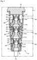
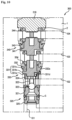
- FIG. 3 is a cross-sectional view showing a specific state in which the check valve of FIGS. 2A and 2B is provided in the valve mounting hole of the modulator block.
- the check valve according to the present embodiment is formed by stacking a plurality of valve parts in a line as illustrated, the check valve may be easily installed in one valve mounting hole provided in a modulator block by replacing the conventional three one-way check valves provided independently on the plurality of flow paths 101-104 provided in the modulator block 1. As a result, it is possible to eliminate the shortage of installation space and to reduce the number of parts due to a simple structure, thereby reducing manufacturing costs and assembly processes.
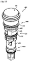
- FIG. 4 is a combined perspective view showing the check valve according to the first embodiment of the present invention
- FIG. 5 is an exploded perspective view showing a check valve according to a first embodiment of the present invention.
- the check valve 100 may include a valve housing 110 having therein a flow path passing through the inside and the outside, and a plurality of valve parts 120, 130, and 140 provided on the flow paths of the valve housing.
- the plurality of valve parts are illustrated as three valve parts including the first valve part 120, the second valve parts 130, and the third valve 140, but the present invention is not limited thereto and may include at least two or more valve parts.
- the valve housing 110 may include a housing body 111 that is provided in a cylindrical shape with one side open, and a housing cap 116 that is engaged with the opening of the housing body 111.
- the housing body 111 is made of a metal material, and the outer and inner shapes of the body may be machined in a forging or other manner to facilitate machining. According to the present embodiment, the housing body 111 may include a first body 111a and a second body 111b.
- the first body 111a is provided in a cup shape with an opening on one side
- the second body 111b is provided with openings on both sides, so that one side of the open sides of the second body 111b is assembled on the open one side of the first body 111a.
- a housing cap 116 is assembled on the other side of the second body 111B.
- the housing body 111 may have a generally cylindrical shape. The ends of the first body 111a and the second body 111b that are assembled together in the longitudinal direction may be firmly joined in such a way as to be press-fitted or cocked.
- the side wall of the cup-shaped housing body 111 may be stepped along the longitudinal direction. This is to allow the plurality of valve parts 120, 130, 140 described above to be seated in the correct position when assembled in the valve housing 110, while allowing the plurality of valve parts 120, 130, 140 to be easily assembled sequentially in the housing body 111.
- the plurality of valve parts 120, 130, 140 may be arranged to sequentially increase in size along the direction of the open end from the closed bottom of the housing body 111 for ease of assembly as shown.
- the housing body 111 has, on a bottom surface of one end thereof, a first body hole 112 for communicating the inside and the outside of the valve housing 110, and may have, at a predetermined interval along a longitudinal direction of a side wall, a second body hole, a third body hole and a fourth body hole that communicate the inside with the outside thereof.
- the first body hole 112 is provided in the longitudinal direction of the housing body 111
- the second, third, and fourth body holes 113, 114, and 115 are provided in a circumferential direction of a housing body 111, but the present invention is not limited thereto.
- a plurality of second, third, and fourth body holes 113,114, and115 may be provided at predetermined intervals along the circumferential direction of the housing body 111.
- the valve housing 110 provided as described above is firmly and closely engaged with a flow path (valve mounting hole) in the shape of a bore formed in the modulator block.
- a flow path valve mounting hole
- the first body hole 112 of the housing body 111 communicates with the first flow path 101 of the modulator block 1
- the second body hole 113 communicate with the second flow path 102
- the third body hole 114 communicates with the third flow path 103
- the fourth body hole 115 is communicated with the fourth flow path 104.
- the plurality of valve parts 120, 130, 140 may include the first valve part 120, the second valve part 130, and the third valve part 140.
- the first valve part 120 may be provided between the first flow path 101 and the second flow path 102.
- an opening/closing member e.g., a ball
- a valve housing 111 so as to be located between at least two adjacent body holes, for example, a first body hole 112 communicating with the first flow path 101 and a second body hole 113 communicating with the second flow path.
- the first valve part 120 may include a first valve seat 121 in which an orifice through which fluid passes is formed, a first ball 122 as an opening/closing member which is selectively in contact with the orifice, a coil spring-like first elastic member 123 which is elastically supported on one side by pressure on the first ball 122, and a first filter cap 124 which is engaged with the first valve seat 121 to receive the first ball 122 and is elastically supported on the other side of the first elastic member 123.
- the first ball 122 is provided so as to be able to selectively contact the inclined first valve surface 121a of the first valve seat 121, the first elastic member 123 is provided to be capable of pressing the first ball 122 to the side of the second valve surface 141a, and the first filter cap 104 elastically presses and supports the first elastic member 123.
- the first filter cap 124 may support the first elastic member 123, and may also function as a spacer for filtering incoming foreign matter and maintaining a distance from other adjacent valve parts.
- the ball is exemplified as an opening/closing member for selectively opening/closing the orifice, but the present invention is not limited thereto, and may be provided in various other forms such as a semicircle and an arc.
- the first valve part 120 may be referred to as a first ball valve part.
- the first valve part 120 forms one independent valve part together with the valve housing 111 by having the first valve seat 121 seated on the bottom surface and the stepped inner wall of the valve housing 111 and the first filter cap 124 engaged with the first valve seat 121 through the first ball 122 and first elastic member 123.
- the first valve part 120 provided as described above allows the fluid to move from the outside to the inside of the housing body 111 (or from the first body hole 112 to the second body hole 113) of the valve housing 10 when the hydraulic pressure of the fluid is greater than the elastic force of the first elastic member 123, but prevents the fluid from moving. Therefore, in the first embodiment, when only the first flow path 101 is used as the inlet flow path of the fluid, the second flow path 102, the third flow path 103, and the fourth flow path[104] may be used as outlet flow paths of the fluids, respectively.
- first, second, and third valve parts 120, 130, 140 having a one-way flow are provided in the housing body 111 so as to pass the fluid in the same direction as in the present embodiment, if the first to third flow paths 101-103 are each used as an independent inlet flow path, the fourth flow path may be used as a common outlet flow path.
- the second valve part 130 may be provided between the second flow path 102 and the third flow path 103, and may be specifically provided in the valve housing 111 between a second body hole 113 communicating with a second flow path 120 and a third body hole 114 communicating with a third flow path 103.
- the second valve part 130 may include a second valve seat 131 having an orifice formed therein, a second ball 132 as an opening/closing member that selectively contacts the orifice, a third elastic member 133 in the shape of a coil spring that is elastically supported on one side by the second ball 132, and a second filter cap 134 that is engaged with the second valve seat 131 and is elastically supported on the other side of the second elastic member 132.
- the second ball 132 is provided so as to be able to selectively contact the inclined second valve surface 131a of the second valve seat 113, the second elastic member 132 may be provided so as to press the second ball 132 toward the first valve surface 131a, and the second filter cap 154 elastically presses and supports the second elastic member 132.
- the second filter cap 134 may support the second elastic member 132, and may also function as a spacer for filtering incoming foreign matter and maintaining a distance from other adjacent valve parts.
- the ball is exemplified as a member for selectively opening/closing the orifice, but the present invention is not limited thereto and may be provided in various other forms such as a semi-circle and an arc.
- the second valve part 130 may be referred to as a second ball valve part.
- the second valve part 130 forms one independent valve part together with the valve housing 111 by the second valve seat 131 being seated on a stepped surface formed in the middle of the valve housing 111 and the second filter cap 134 being engaged with the second valve seat 131 through the second ball 132 and second elastic member 133.
- the second valve seat 131 of the first valve part 120 may be supported in contact with the first filter cap 124 thereof.
- the second valve part 130 provided as described above allows the fluid inside the valve housing 110 to move from the second body hole 113 to the third body hole 114 when the hydraulic pressure of the fluid is greater than the elastic force of the second elastic member 132, but prevents the fluid from moving. Therefore, in the first embodiment, when the second flow path 102 is used as the inlet flow path of the fluid together with the first flow path 101, the third flow path and the fourth flow path may be used respectively or together as the outlet flow path for the fluid.
- the fourth flow path 104 may be used as a common outlet flow path if the first flow path to the third flow path are used as independent inlet flow paths.
- the hydraulic pressure of the fluid flowing through the first flow path 101 is greater than the elastic force of the elastic members 123, 133, and 143 of the valve part, the fluid that has passed the first valve part 120 may be transmitted to the second valve part 130 and the third valve parts 140.
- the third valve part 140 may be provided between the third flow path 103 and the fourth flow path 104, and specifically, is provided in the valve housing 111, specifically, the second body 11 1b, between a third body hole 114 communicating with the third fluid path 103 and a fourth body hole115 communicating therewith.
- the third valve part 140 may include a third valve seat 141 having an orifice formed therein, a third ball 142 as an opening/closing member selectively in contact with the orifice, a fourth elastic member 143 in the shape of a coil spring which is elastically supported on one side by the third ball 142, and a third filter cap 144 which is engaged with the third valve seat 141 and is elastically supported on the other side of the third elastic member 144.
- the third ball 142 is provided so as to be selectively in contact with the inclined third valve surface 121a of the third valve seat 131, the third elastic member 143 is configured to be able to press the third ball 142 toward the third valves surface 141a, and the third filter cap 144 elastically presses and supports the third elastic member 143.
- the third filter cap 144 may support the third elastic member 143, and may also function as a spacer for filtering incoming foreign matter and maintaining a distance from other adj acent valve parts.
- the ball is exemplified as a member for selectively opening/closing the orifice, but the present invention is not limited thereto and may be provided in various other forms such as a semi-circle and an arc.
- the third valve part 140 may be referred to as a third ball valve part.
- the third valve part 140 forms one independent valve part together with the valve housing 111 by the third valve seat 141 being seated on a stepped surface formed on the bottom side of the second body 111b of the valve housing 111 and the third filter cap 144 being engaged with the third valve seat 141 through the third ball 142 and the third elastic member 143 that are interposed.
- the third valve seat 141 of the second valve part 130 may be supported on one side by being in contact with the second filter cap 134 and on the other side by contacting the housing cap 116.
- the third valve part 140 which is provided as described above, allows the fluid passing through the orifice of the third valve part 140 to move from the third body hole 114 to the fourth body hole 115, but prevents the fluid from moving, when the hydraulic pressure of the fluid flowing in is greater than the elastic force of the second elastic member 132. Therefore, in the present first embodiment, when the third flow path 103 is used as an inlet flow path for fluid together with the first flow path and the second flow path, the fourth flow path may be used as the outlet flow path of the fluid.
- the fourth flow path 104 may be used as a common outlet flow path if the first flow path to the third flow path are used as independent inlet flow paths.
- the hydraulic pressure of the fluid flowing through the first flow path 101 is greater than the elastic force of the first elastic member 123 of the first valve part 120 and when the hydraulic pressure of fluid that flows through the second flow path 102 is greater than the spring force of the second elastic member 132 of the second valve part 130, the fluid that has passed the first valve part 120 is transmitted to the second valves 140.
- the check valve 100 when fluid flows into the interior of the modulator block through the first flow path 101 to which the first valve part 120 is connected, the second flow path 102 to each of which the second valve part 130 is connected and the third flow path 103 to which the third valve part 140 is connected among the plurality of flow paths 101-104 of the hydraulic control unit provided in the modulator block, it is possible to discharge the fluid to the exterior of the modulator block through the fourth flow path 104.
- first flow path 101 may be used as an inlet flow path and the second flow path 102 may be use as an outlet flow path
- first and second flow paths 101, 102 may also be used for common outlet flow paths.
- FIG. 6 is a combined sectional view showing a check valve according to a (2-1)th embodiment of the present invention.
- the check valve 200A according to the (2-1)th embodiment will be described mainly in terms of differences from the check valves 100 of the above-described first embodiment, and the same reference numerals as in the first embodiment perform the same functions, and detailed description thereof will be omitted.
- the cylinder-shaped housing body 211 open on one side is provided integrally without being separated into two, and it is the same that a stepped portion is formed on the side wall along the longitudinal direction and the open end is engaged with the housing cap 216.
- the sizes of the plurality of valve parts 120, 130, 140 sequentially increase along an end direction open from the bottom of the housing body 211.
- the housing body 211 is an integrated check valve 200A in which the first valve part 120, the second valve part 130, and the third valve part 140 are sequentially seated inside, and then the first, second, and third valve parts 120, 130, 140 are stacked in a line on one housing body 211 while being hermetically assembled with the housing cap 216.
- FIG. 7 is a combined sectional view showing a check valve according to a (2-2)th embodiment of the present invention.
- the check valve 200B according to the (2-2)th embodiment will be described mainly in terms of differences from the check valve of the first embodiment, and the same reference numerals as those in the 1st embodiment perform the same functions, and detailed description thereof will be omitted.
- the housing body 211 in the shape of a cylinder open on one side is separated into the first body 111a and the second body 311b in the same manner as in the first embodiment, and at least one valve part is provided in each of the bodies 101a, 101b.
- one valve part 120 is provided in the first body 211a on the lower side in the longitudinal direction
- two valve parts 130, 140 are provided in a second body 211b on the upper side.
- a step is formed in the side wall of the housing body 211 along the longitudinal direction, and the housing cap 216 is engaged with the end of the open housing body 211.
- the sizes of the plurality of valve parts 120, 130, 140 sequentially increase along an end direction open from the bottom of the housing body 211.
- the housing body 211 is an integrated check valve 200B in which the first, second, and third valve parts 120, 130, 140 are sequentially seated and then hermetically assembled with the housing cap 116, with the first, second, and third valves 120, 130, 140 disposed in a line on one housing body 211.
- the check valve 200B provided as described above is relatively excellent in product stability because the check valve 200B is less deformed against the pressure applied when the modulator block is assembled, as compared with the check valve 100 of the first embodiment.
- FIG. 8 is a combined sectional view showing a check valve according to a (2-3)th embodiment of the present invention.
- the check valve 200C according to the present (2-3)th embodiment will be described focusing on the difference from the above-described check valve 200B in a (2-2)th embodiment, and the same reference numerals as those of the second to second embodiment perform the same functions, and detailed description thereof will be omitted.
- the housing body 211 in the shape of a cylinder open on one side is separately provided as the first body 211a and the second body 211b, and at least one valve part is provided in each of the bodies 121a, 211b.
- one valve part 120' is provided in the lower first body 211a in the longitudinal direction
- two valve parts 130', 140 are provided in an upper second body 211b.
- a step is formed in the side wall of the housing body 211 along the longitudinal direction, and the housing cap 216 is engaged with the end of the open housing body 211.
- the sizes of the plurality of valve parts 120', 130', 140 sequentially increase along an end direction open from the bottom of the housing body 211.
- the housing body 211 is an integral check valve 200C in which the first, second, and third valve parts 120', 130', 140 are sequentially seated and then hermetically assembled by the housing cap 116, with the first, second, and third valve parts 120',130', 140 stacked in a line on one housing body.
- the first valve part 120' and the second valve parts 130' are each free of a valve seat, and only the third valve part 140 has the valve seat 141. That is, the first valve part 120' and the second valve parts 130' function as orifices for selectively opening/closing the first and second body holes 212a and 212b, respectively, provided in the first body 211a and the second body 211b of the housing body 211, in direct contact with the first ball 122 and the second ball 132, which are opening/closing members.
- the check valve 200C provided as described above may further simplify the structure by reducing the number of components as compared with the check valves 200B of the (2-2)th embodiment.
- FIGS. 9 and 10 are an engagement perspective view of a check valve according to a third embodiment of the present invention and a sectional view showing a modulator block with which the check valve is engaged.
- the check valve 300 according to the third embodiment will be described mainly in terms of differences from the check valves 100, 200A-200C of the above-described first and second embodiments, and the same reference numerals as in the first and the second embodiments perform the same functions, and detailed description thereof will be omitted.
- the check valve 300 may be integrated by stacking the first valve part 320, the second valve part 330, and the third valve unit 340 and the housing cap 316 in a line without a valve housing, and thus the check valve in which a plurality of valve units are integrated may be simply engaged with the bore (valve mounting groove) 2 provided in the modulator block 1.
- a second valve seat 331 of the second valve part 330 adjacent to the first filter cap 324 of the first valve part 320 may be fastened by an engaging method such as forced press-fitting or rotation jamming
- the third valve seat 341 of the third valve part 340 adjacent to the second filter cap 334 of the second valve part 330 may be fastened by an engaging method such as forced press-fitting or rotation jamming
- the housing cap 316 may be finally fastened to the third filter cap 344 of the third valve unit 340 by an engaging method such as forced press-fitting or rotational engagement.
- the first valve part 320 may employ a ball-seat type using balls as the flow path opening/closing member as described above, but the second and third valve parts 330 and 340 may adopt a lip-seal type using a lip seal as well as a ball seat type as the opening/closing member of the flow path.
- a second lip seal 332 serving as an opening/closing member provided in the second valve part 330 may be provided between the second valve seat 331 and the second filter cap 334.
- the second valve seat 331 is provided in a cylindrical shape and may include a small-diameter head 321a, a large-diameter flange 321b, and a smaller-diameter valve body 321c.
- the hollow second lip seal 332 is engaged with the valve body 331c of the second valve seat 331.
- the second lip seal 332 is fixed in position in the front-rear direction of the fluid flow while being supported on both sides by the flange 331b of the second valve seat 331 and the second filter cap 334.
- the second lip seal 332 may have a second lip sealing surface 332a in the shape of an inclined surface with an outer diameter extending from the upstream side to the downstream side in the fluid flow direction to allow movement of fluid while being selectively contacted by hydraulic pressure with the inner surface of the bore 2 provided in the modulator block 1.
- an undescribed reference numeral 331d denotes a valve flow path provided in the shape of a groove between the head 331a and the flange 331b of the second valve seat 331.
- the third valve part 340 is also provided with a third valve seat 341 having a head, a flange, a valve body and a valve flow path, a third lip seal 342, and a third filter cap 344, and each member operates in the same manner as the second valve part 330 except for the diameter thereof, and thus a detailed description thereof is omitted.
- the check valve 300 according to the third embodiment is inserted and fixed in the bore 2 of the modulator block 1, as shown in FIG. 10 , so that the plurality of flow paths 101 to 104, the first valve part 320, the second valve part 330, and the third valve part 340 selectively communicate with each other.
- fluid that has flowed into the modulator block 1 independently through at least one inlet flow path of the plurality of flow paths 101-104 may be discharged to the outside of the modulator block 1 through another outlet flow path.
- FIGS. 11 and 12 are a combined perspective view of a check valve according to a fourth embodiment of the present invention and a sectional view showing a modulator block with which the check valve is engaged.
- the check valve 400 according to the fourth embodiment will be described focusing on the difference from the check valve 300 of the third embodiment, and the same reference numerals as in the first, second, and third embodiments perform the same functions, and detailed description thereof will be omitted.
- the check valve 400 according to the fourth embodiment has a simpler form than the check valve 300 of the third embodiment, and the second valve part 430 and the third valve part 440 include the valve blocks 435, 445 and the lip seals 432, 442, and no filter cap is provided.
- the first valve part 420 has a ball-seat structure
- the second valve part 430 and the third valve part 440 have a lip-seal structure.
- the first valve part 420 includes the first valve seat 421, the first ball 422, and the first elastic member 423 as described above. However, the first ball 422 and the first elastic member 423 are supported by the first valve block 425 which is engaged with the second valve seat 421. In other words, the first valve block 425 has a front end engaged with the second valve seat 421 and a rear end engaged with the second valve block 435 through the first block protrusion 426.
- the first filter member 424 is provided in front of the fluid flow of the first valve seat 421, and the undescribed reference numeral s denotes a seal member provided in the first valve seat 421.
- the second valve part 430 includes a second lip seal 432 and a second valve block 435.
- the second valve block 435 includes a second block head groove 437 with which the first block protrusion 426 of the first valve part 420 is engaged in front of the fluid flow, and the second lip seal 432 is engaged with the second block protrusion 436 provided behind the fluid flow of the second valve body 435.
- the second lip seal 432 may be supported on both sides by a flange of the second valve body 435 and a third valve block 445 of the third valve part 440.
- the second valve block 435 according to the fourth embodiment is formed integrally with the valve seat of the third embodiment and the filter cap, and may be in the shape of one single member.
- the third valve part 440 includes a third lip seal 442 and a third valve block 445.
- the third valve block 445 includes a third block head groove 447 with which the second block protrusion 436 of the second valve part 410 is engaged in front of the fluid flow, and the third lip seal 442 is engaged with the third block protrusion 446 provided in the rear of the fluid flow of the third valve block 445.
- the third lip seal 442 may be stably supported on both sides by the flange of the third valve block 445 and the housing cap 416.
- the check valve 400 according to the fourth embodiment is inserted into and fixed to the bore 2 of the modulator block 1 as shown in FIG. 12 , so that the plurality of flow paths 101-104, the first valve part 420 and the second and third valve parts 430 and 440 may selectively communicate with each other.
- fluid that has flowed into the modulator block 1 independently through at least one inlet flow path of the plurality of flow paths 101-104 may be discharged to the outside of the modulator block 1 through another outlet flow path.
- valve parts e.g., a first valve part, a second valve part and a third valve part are provided in the same direction of fluid flow in one valve housing or in a bore of a modulator block
- the present invention is not limited thereto and may be provided in more various forms through suitable variations and modifications.
- valve housing and the flow path provided in the bore of the modulator block are parallel to each other as well as may be changed and modified in any suitable form such as "L", "T” or "+”.
Landscapes
- Engineering & Computer Science (AREA)
- General Engineering & Computer Science (AREA)
- Mechanical Engineering (AREA)
- Transportation (AREA)
- Regulating Braking Force (AREA)
Applications Claiming Priority (2)
| Application Number | Priority Date | Filing Date | Title |
|---|---|---|---|
| KR20200046398 | 2020-04-17 | ||
| PCT/KR2021/004858 WO2021210967A1 (fr) | 2020-04-17 | 2021-04-19 | Clapet antiretour et système de frein comprenant celui-ci |
Publications (2)
| Publication Number | Publication Date |
|---|---|
| EP4137725A1 true EP4137725A1 (fr) | 2023-02-22 |
| EP4137725A4 EP4137725A4 (fr) | 2024-05-15 |
Family
ID=78083750
Family Applications (1)
| Application Number | Title | Priority Date | Filing Date |
|---|---|---|---|
| EP21789176.1A Pending EP4137725A4 (fr) | 2020-04-17 | 2021-04-19 | Clapet antiretour et système de frein comprenant celui-ci |
Country Status (4)
| Country | Link |
|---|---|
| US (1) | US20230160486A1 (fr) |
| EP (1) | EP4137725A4 (fr) |
| CN (1) | CN115956175A (fr) |
| WO (1) | WO2021210967A1 (fr) |
Cited By (2)
| Publication number | Priority date | Publication date | Assignee | Title |
|---|---|---|---|---|
| EP4421320A1 (fr) * | 2023-02-23 | 2024-08-28 | Hamilton Sundstrand Corporation | Clapet de non-retour pour pompe d'escamotage d'une turbine à air dynamique (rat) |
| EP4180289B1 (fr) * | 2020-07-29 | 2025-04-02 | Shenzhen Yinwang Intelligent Technologies Co., Ltd. | Unité de réglage hydraulique, système de freinage, véhicule et procédé de commande |
Families Citing this family (1)
| Publication number | Priority date | Publication date | Assignee | Title |
|---|---|---|---|---|
| US20240301924A1 (en) * | 2023-03-07 | 2024-09-12 | Arctic Cat Inc. | Duct valve for clutch assembly in off-road vehicles |
Family Cites Families (44)
| Publication number | Priority date | Publication date | Assignee | Title |
|---|---|---|---|---|
| US17530A (en) * | 1857-06-09 | Gas-burner | ||
| US183806A (en) * | 1876-10-31 | Improvement in pump cylinders and valves | ||
| US2707485A (en) * | 1949-08-13 | 1955-05-03 | Milton Roy Co | Pump and valve unit |
| US3491788A (en) * | 1966-06-27 | 1970-01-27 | Precision Chem Pump Corp | Air bleed and syphon breaker valve construction |
| US3661167A (en) * | 1970-05-25 | 1972-05-09 | A & D Fabricating Co | Chemical feed pump with improved valve means |
| US3746038A (en) * | 1971-01-25 | 1973-07-17 | Parker Hannifin Corp | Fuel head compensating valve for fuel injection nozzle |
| US4253524A (en) * | 1979-06-21 | 1981-03-03 | Kobe, Inc. | High flow check valve apparatus |
| JPH037251Y2 (fr) * | 1985-07-03 | 1991-02-22 | ||
| US5002662A (en) * | 1988-09-07 | 1991-03-26 | Spectra-Physics, Inc. | Check valve |
| JPH06286984A (ja) * | 1993-03-31 | 1994-10-11 | Koretsuku Kk | 油圧ジャッキ |
| JPH0714183U (ja) * | 1993-08-05 | 1995-03-10 | 自動車機器株式会社 | 液圧式ブレーキ倍力装置用チェックバルブ組立体 |
| JPH1113929A (ja) * | 1997-06-23 | 1999-01-22 | Sanwa Seiki Co Ltd | 油圧切換弁 |
| JP4320968B2 (ja) * | 2000-05-02 | 2009-08-26 | トヨタ自動車株式会社 | ブレーキシステム |
| NO316090B1 (no) * | 2002-03-21 | 2003-12-08 | Nat Oilwell Norway As | Anordning ved ventil for stempelmaskin så som pumpe og kompressor |
| US6880570B2 (en) * | 2003-08-14 | 2005-04-19 | Delphi Technologies, Inc. | Vehicle actuator |
| US7147002B2 (en) * | 2003-10-28 | 2006-12-12 | Victaulic Company | Modular multi-function fluid flow control device |
| CN100360356C (zh) * | 2004-10-25 | 2008-01-09 | 株式会社万都 | 电磁阀 |
| US7237569B2 (en) * | 2005-03-09 | 2007-07-03 | Globe Union Industrial Corp. | Ball check valve |
| DE102006010706A1 (de) * | 2006-03-08 | 2007-09-13 | Schaeffler Kg | Ventil für strömende Medien |
| KR101332693B1 (ko) | 2012-02-10 | 2013-11-26 | 주식회사 만도 | 차량용 전자식 브레이크 시스템 |
| CN203718061U (zh) * | 2014-01-21 | 2014-07-16 | 吴昭昌 | 气体注入装置的止逆阀与气体注入装置 |
| CN105464735B (zh) * | 2014-08-27 | 2019-09-10 | 舍弗勒技术股份两合公司 | 端部供油的机油控制阀及其组装方法 |
| CN204358179U (zh) * | 2014-12-16 | 2015-05-27 | 绵阳富临精工机械股份有限公司 | 一种发动机主油道二级单向阀 |
| KR102288949B1 (ko) * | 2015-01-22 | 2021-08-12 | 현대모비스 주식회사 | 자동차의 브레이크 시스템 |
| US10914057B2 (en) * | 2016-10-14 | 2021-02-09 | Michael Anthony Di Monte | Dual air admittance valve |
| US11993925B2 (en) * | 2015-04-23 | 2024-05-28 | Michael Anthony Di Monte | Dual air admittance valve |
| CN204756029U (zh) * | 2015-05-19 | 2015-11-11 | 浙江力泰新能源科技有限公司 | 一种止回阀 |
| CN204842000U (zh) * | 2015-07-06 | 2015-12-09 | 福建西河卫浴科技有限公司 | 一种具有止逆结构的限流装置 |
| JP6523844B2 (ja) * | 2015-07-18 | 2019-06-05 | ボーグワーナー インコーポレーテッド | 一体型チェック・リリーフバルブ |
| KR20170059039A (ko) * | 2015-11-19 | 2017-05-30 | 주식회사 만도 | 전자식 브레이크 시스템 |
| CN205401838U (zh) * | 2016-03-08 | 2016-07-27 | 任焕轩 | 一种lng车载气瓶加液口 |
| CN205745364U (zh) * | 2016-06-12 | 2016-11-30 | 中国石油化工股份有限公司 | 割缝式稠油掺水单流阀 |
| KR101888497B1 (ko) * | 2016-12-27 | 2018-08-14 | 이래에이엠에스 주식회사 | 차량의 브레이크 시스템용 피스톤 펌프 |
| KR102291118B1 (ko) * | 2017-05-23 | 2021-08-20 | 주식회사 만도 | 전자식 브레이크 시스템 |
| CN107202182B (zh) * | 2017-08-05 | 2023-05-16 | 李微 | 单向阀 |
| CN207195756U (zh) * | 2017-09-01 | 2018-04-06 | 东莞市北泽五金科技有限公司 | 一种单向流体阀门 |
| CN109720327B (zh) * | 2017-10-20 | 2022-08-02 | 株式会社万都 | 止回阀 |
| KR102079023B1 (ko) * | 2017-11-06 | 2020-02-19 | 주식회사 만도 | 일체형 솔레노이드밸브 및 그를 이용한 브레이크 시스템 |
| KR102559207B1 (ko) * | 2018-05-30 | 2023-07-25 | 에이치엘만도 주식회사 | 체크밸브 |
| CN209196190U (zh) * | 2018-10-27 | 2019-08-02 | 浙江苍南仪表集团股份有限公司 | 一种止回过滤机构的流量调节结构 |
| KR102602359B1 (ko) * | 2018-11-22 | 2023-11-16 | 에이치엘만도 주식회사 | 체크밸브 및 이를 포함하는 모듈레이터블록 |
| CN209622131U (zh) * | 2019-01-29 | 2019-11-12 | 成都瑞恒达机电设备有限公司 | 一种加液枪中单向阀密封结构 |
| DE102020109615A1 (de) * | 2020-04-07 | 2021-10-07 | Neumeister Hydraulik Gmbh | Vorrichtung zum halten eines schafts eines hydraulikzylinders in stellung und verfahren zum entsperren und absperren eines sekundär-rückschlagventils der vorrichtung |
| KR20220083884A (ko) * | 2020-12-11 | 2022-06-21 | 현대모비스 주식회사 | 브레이크 시스템용 피스톤펌프 |
-
2021
- 2021-04-19 WO PCT/KR2021/004858 patent/WO2021210967A1/fr not_active Ceased
- 2021-04-19 CN CN202180037316.6A patent/CN115956175A/zh active Pending
- 2021-04-19 US US17/919,521 patent/US20230160486A1/en active Pending
- 2021-04-19 EP EP21789176.1A patent/EP4137725A4/fr active Pending
Cited By (3)
| Publication number | Priority date | Publication date | Assignee | Title |
|---|---|---|---|---|
| EP4180289B1 (fr) * | 2020-07-29 | 2025-04-02 | Shenzhen Yinwang Intelligent Technologies Co., Ltd. | Unité de réglage hydraulique, système de freinage, véhicule et procédé de commande |
| EP4421320A1 (fr) * | 2023-02-23 | 2024-08-28 | Hamilton Sundstrand Corporation | Clapet de non-retour pour pompe d'escamotage d'une turbine à air dynamique (rat) |
| US12449049B2 (en) | 2023-02-23 | 2025-10-21 | Hamilton Sundstrand Corporation | Check valve for RAT restow pump |
Also Published As
| Publication number | Publication date |
|---|---|
| WO2021210967A1 (fr) | 2021-10-21 |
| EP4137725A4 (fr) | 2024-05-15 |
| CN115956175A (zh) | 2023-04-11 |
| US20230160486A1 (en) | 2023-05-25 |
Similar Documents
| Publication | Publication Date | Title |
|---|---|---|
| EP3560776B1 (fr) | Système de frein électronique et son procédé de fonctionnement | |
| US12194968B2 (en) | Electronic brake system and operation method | |
| EP4137725A1 (fr) | Clapet antiretour et système de frein comprenant celui-ci | |
| US11993233B2 (en) | Electric brake system and operation method | |
| EP4129780B1 (fr) | Système de frein électronique | |
| US12145561B2 (en) | Electronic brake system and method for operating same | |
| KR20220006015A (ko) | 전자식 브레이크 시스템 및 이의 작동방법 | |
| US12194969B2 (en) | Electronic brake system and method for operating same | |
| US12187247B2 (en) | Electronic brake system | |
| US7967393B2 (en) | Pressure balanced supply valve for vehicle brake system with integrated low pressure accumulator | |
| KR20200128281A (ko) | 전자식 브레이크 시스템 및 이의 작동방법 | |
| KR20200138584A (ko) | 전자식 브레이크 시스템 및 이의 작동방법 | |
| KR102932464B1 (ko) | 전자식 브레이크 시스템 및 이의 작동방법 | |
| KR102897737B1 (ko) | 전자식 브레이크 시스템 및 이의 작동방법 | |
| KR102693190B1 (ko) | 전자식 브레이크 시스템 및 작동방법 | |
| KR20220094476A (ko) | 전자식 브레이크 시스템 및 이의 작동방법 | |
| KR102893397B1 (ko) | 전자식 브레이크 시스템 | |
| KR20220000377A (ko) | 전자식 브레이크 시스템 | |
| US20240059265A1 (en) | Electronic brake system | |
| KR20250150987A (ko) | 전자식 브레이크 시스템 | |
| KR20200109430A (ko) | 전자식 브레이크 시스템 | |
| KR20200107397A (ko) | 전자식 브레이크 시스템용 마스터 실린더 | |
| KR20220040720A (ko) | 전자식 브레이크 시스템 | |
| KR102567761B1 (ko) | 전자식 브레이크 시스템 | |
| CN121947423A (zh) | 电动制动系统以及控制电动制动系统的方法 |
Legal Events
| Date | Code | Title | Description |
|---|---|---|---|
| STAA | Information on the status of an ep patent application or granted ep patent |
Free format text: STATUS: THE INTERNATIONAL PUBLICATION HAS BEEN MADE |
|
| PUAI | Public reference made under article 153(3) epc to a published international application that has entered the european phase |
Free format text: ORIGINAL CODE: 0009012 |
|
| STAA | Information on the status of an ep patent application or granted ep patent |
Free format text: STATUS: REQUEST FOR EXAMINATION WAS MADE |
|
| 17P | Request for examination filed |
Effective date: 20221111 |
|
| AK | Designated contracting states |
Kind code of ref document: A1 Designated state(s): AL AT BE BG CH CY CZ DE DK EE ES FI FR GB GR HR HU IE IS IT LI LT LU LV MC MK MT NL NO PL PT RO RS SE SI SK SM TR |
|
| RAP3 | Party data changed (applicant data changed or rights of an application transferred) |
Owner name: HL MANDO CORPORATION |
|
| DAV | Request for validation of the european patent (deleted) | ||
| DAX | Request for extension of the european patent (deleted) | ||
| REG | Reference to a national code |
Ref country code: DE Ref legal event code: R079 Free format text: PREVIOUS MAIN CLASS: F16K0027020000 Ipc: F16K0011100000 |
|
| A4 | Supplementary search report drawn up and despatched |
Effective date: 20240417 |
|
| RIC1 | Information provided on ipc code assigned before grant |
Ipc: B60T 13/14 20060101ALI20240411BHEP Ipc: B60T 13/68 20060101ALI20240411BHEP Ipc: F16K 27/02 20060101ALI20240411BHEP Ipc: F16K 15/04 20060101ALI20240411BHEP Ipc: F16K 11/10 20060101AFI20240411BHEP |