EP4169755B1 - Agencement de radiateur pour véhicule et véhicule - Google Patents
Agencement de radiateur pour véhicule et véhicule Download PDFInfo
- Publication number
- EP4169755B1 EP4169755B1 EP21203347.6A EP21203347A EP4169755B1 EP 4169755 B1 EP4169755 B1 EP 4169755B1 EP 21203347 A EP21203347 A EP 21203347A EP 4169755 B1 EP4169755 B1 EP 4169755B1
- Authority
- EP
- European Patent Office
- Prior art keywords
- radiator
- louvers
- guiding element
- air guiding
- inlet
- Prior art date
- Legal status (The legal status is an assumption and is not a legal conclusion. Google has not performed a legal analysis and makes no representation as to the accuracy of the status listed.)
- Active
Links
Images


Classifications
-
- B—PERFORMING OPERATIONS; TRANSPORTING
- B60—VEHICLES IN GENERAL
- B60K—ARRANGEMENT OR MOUNTING OF PROPULSION UNITS OR OF TRANSMISSIONS IN VEHICLES; ARRANGEMENT OR MOUNTING OF PLURAL DIVERSE PRIME-MOVERS IN VEHICLES; AUXILIARY DRIVES FOR VEHICLES; INSTRUMENTATION OR DASHBOARDS FOR VEHICLES; ARRANGEMENTS IN CONNECTION WITH COOLING, AIR INTAKE, GAS EXHAUST OR FUEL SUPPLY OF PROPULSION UNITS IN VEHICLES
- B60K11/00—Arrangement in connection with cooling of propulsion units
- B60K11/08—Air inlets for cooling; Shutters or blinds therefor
-
- B—PERFORMING OPERATIONS; TRANSPORTING
- B60—VEHICLES IN GENERAL
- B60K—ARRANGEMENT OR MOUNTING OF PROPULSION UNITS OR OF TRANSMISSIONS IN VEHICLES; ARRANGEMENT OR MOUNTING OF PLURAL DIVERSE PRIME-MOVERS IN VEHICLES; AUXILIARY DRIVES FOR VEHICLES; INSTRUMENTATION OR DASHBOARDS FOR VEHICLES; ARRANGEMENTS IN CONNECTION WITH COOLING, AIR INTAKE, GAS EXHAUST OR FUEL SUPPLY OF PROPULSION UNITS IN VEHICLES
- B60K11/00—Arrangement in connection with cooling of propulsion units
- B60K11/02—Arrangement in connection with cooling of propulsion units with liquid cooling
- B60K11/04—Arrangement or mounting of radiators, radiator shutters, or radiator blinds
-
- B—PERFORMING OPERATIONS; TRANSPORTING
- B60—VEHICLES IN GENERAL
- B60K—ARRANGEMENT OR MOUNTING OF PROPULSION UNITS OR OF TRANSMISSIONS IN VEHICLES; ARRANGEMENT OR MOUNTING OF PLURAL DIVERSE PRIME-MOVERS IN VEHICLES; AUXILIARY DRIVES FOR VEHICLES; INSTRUMENTATION OR DASHBOARDS FOR VEHICLES; ARRANGEMENTS IN CONNECTION WITH COOLING, AIR INTAKE, GAS EXHAUST OR FUEL SUPPLY OF PROPULSION UNITS IN VEHICLES
- B60K11/00—Arrangement in connection with cooling of propulsion units
- B60K11/08—Air inlets for cooling; Shutters or blinds therefor
- B60K11/085—Air inlets for cooling; Shutters or blinds therefor with adjustable shutters or blinds
-
- Y—GENERAL TAGGING OF NEW TECHNOLOGICAL DEVELOPMENTS; GENERAL TAGGING OF CROSS-SECTIONAL TECHNOLOGIES SPANNING OVER SEVERAL SECTIONS OF THE IPC; TECHNICAL SUBJECTS COVERED BY FORMER USPC CROSS-REFERENCE ART COLLECTIONS [XRACs] AND DIGESTS
- Y02—TECHNOLOGIES OR APPLICATIONS FOR MITIGATION OR ADAPTATION AGAINST CLIMATE CHANGE
- Y02T—CLIMATE CHANGE MITIGATION TECHNOLOGIES RELATED TO TRANSPORTATION
- Y02T10/00—Road transport of goods or passengers
- Y02T10/80—Technologies aiming to reduce greenhouse gasses emissions common to all road transportation technologies
- Y02T10/88—Optimized components or subsystems, e.g. lighting, actively controlled glasses
Definitions
- the invention relates to a radiator arrangement for a vehicle.
- the radiator arrangement comprises a radiator and an air guiding element for guiding an airflow towards the radiator.
- the air guiding element has an inlet for letting in the airflow and an outlet facing the radiator.
- the air guiding element comprises a plurality of louvers which are configured to prevent stones of a predetermined size to hit the radiator.
- the invention further relates to a vehicle with such a radiator arrangement.
- Document FR 3 076 496 A1 describes an air guide comprising a duct configured to direct a flow of air entering a motor vehicle towards a heat exchanger.
- the air guide comprises a protective grille for protecting the heat exchanger.
- a flap assembly is mounted within the duct of the air guide by means of a flap support.
- the throttle device for adjusting an airflow through an opening in a vehicle body.
- the throttle device comprises a frame through which the airflow is guided towards a radiator of the vehicle.
- the frame has longitudinal guides along which louvers can slide between an open position and a closed position. If the louvers are moved into the open position, the airflow can pass through the frame. If the louvers are moved into the closed position, the louvers prevent the air from passing through the frame.
- Document DE 10 2010 038 194 A1 describes an adjustable guiding device for controlling external air flowing towards a radiator.
- the guiding device comprises an upper shutter assembly and a lower air flap.
- the upper shutter assembly and the lower air flap are linked by a coupling mechanism and can therefore be moved simultaneously.
- Document KR 20150071268 A describes an airflow guide device for a vehicle, wherein the airflow guide device comprises an upper air flap device and a lower air flap device.
- the inventive radiator arrangement comprises a radiator and an air guiding element for guiding an airflow towards the radiator.
- the air guiding element has an inlet for letting in the airflow and an outlet facing the radiator.
- the air guiding element comprises a plurality of louvers which are configured to prevent stones of a predetermined size to hit the radiator.
- the louvers are fixed in position relative to a housing of the air guiding element, wherein the housing is configured to guide the airflow towards the outlet.
- the outlet has a cross-sectional area at least encompassing an area of a front face of the radiator, wherein the front face of the radiator is exposed to the airflow.
- the radiator arrangement comprises a shutter assembly arranged at the air guiding element.
- the shutter assembly comprises a plurality of louvers which are movable with respect to a frame structure of the shutter assembly.
- the movable louvers of the shutter assembly can contribute to the stone chip protection provided by the immobile louvers, i.e. the louvers which are fixed in position relative to the housing of the air guiding element. Consequently, providing the shutter assembly is helpful in preventing stones from getting to or hitting the front face of the radiator.
- the shutter assembly is arranged at the inlet of the air guiding element, wherein the frame structure is fixed to a frame element of the air guiding element.
- Such a configuration prevents the airflow from entering the air guiding element, if the movable louvers of the shutter assembly are moved into the closed position. This is beneficial, in particular with respect to the aerodynamic properties of the vehicle equipped with the radiator arrangement, i.e. in which the radiator arrangement is installed.
- the air guiding element comprises a center strut dividing the inlet into a first inlet portion and a second inlet portion.
- a first group of louvers is arranged within the first inlet portion
- a second group of louvers is arranged within the second inlet portion.
- the radiator arrangement comprises a mechanism for moving the movable louvers into their various positions, wherein the mechanism is arranged in front of the center strut.
- the louvers As the louvers are fixed in position relative to the housing of the air guiding element and are therefore immobile, the louvers permanently prevent stones of the predetermined size to hit the radiator. This results in a particularly reliable and efficient stone chip protection. Further, as the housing of the air guiding element shields the airflow towards the environment in operation of the radiator arrangement, i.e. when the airflow actually passes through the air guiding element, the entire airflow reaching the front face of the radiator in operation of the radiator arrangement benefits from the retention of the stones, which is provided by the immobile louvers.
- the front face comes to lie within the outlet, in particular centrally within the outlet, if the area of the front face of the radiator is smaller than the cross-sectional area of the outlet.
- the cross-sectional area of the outlet can substantially correspond to the area of the front face of the radiator. This leads to a particularly extensive utilization of the cooling performance that can be provided by the airflow reaching the radiator.
- the immobile louvers or louvers fixed in position are not configured to be moved, in particular rotated, from a first position into a second position. Rather the positions and orientations of the immobile louvers remain permanently unchanged.
- integrating the immobile louvers into the air guiding element makes it unnecessary to provide a stone chip protection grill as a separate component. Further, the effort associated with mounting such an additional component to the radiator is avoided. This results in a simpler manufacturing of the radiator arrangement and in a cost reduction.
- louvers which are part of the air guiding element only lead to a very little increase of the pressure loss on the airflow side of the radiator compared to the pressure loss resulting from a separate stone chip protection grill fixed to the front face of the radiator. Still further, as there is no need for fixing a separate component such as the stone chip protection grill to the radiator, leakages between the housing of the air guiding element and the radiator front face can be reduced.
- the radiator is protected against damages resulting from stones hitting the front face of the radiator, a loss of a cooling fluid, in particular a cooling liquid, flowing through the radiator in operation of the radiator arrangement can be avoided to a particularly large extent. Therefore, the functionality of the radiator can be readily maintained.
- the louvers fixed in position can also protect the radiator from damage by reducing the kinetic energy of stones reaching the front face of the radiator. As the probability is reduced that even stones smaller than the predetermined size hit the radiator with full speed, a reliable and efficient stone chip protection is provided.
- the radiator arrangement In operation of the radiator arrangement, i.e. when the airflow actually flows through the housing of the air guiding element towards the front face of the radiator, a transfer of heat from the cooling fluid towards the airflow passing through the radiator (or vice versa from the airflow towards the cooling fluid) can occur. Therefore the cooling fluid can be cooled by means of the radiator.
- the airflow can preferably be effected by the movement of the vehicle equipped with the radiator arrangement and/or by means of a cooling fan which can be part of the radiator arrangement.
- the louvers are configured as plate like elements having a narrow side facing the airflow and upper and lower faces which are oriented substantially parallel to the airflow.
- Such a shape and orientation of the immobile or fixed louvers leads to a particularly low pressure loss during operation of the radiator arrangement, i.e. when the airflow actually passes through the air guiding element and reaches the front face of the radiator and then passes through the radiator. Consequently, providing the louvers as the plate like elements results in a particularly small pressure loss associated with the louvers.
- the louvers are made in one piece with the housing of the air guiding element. This results in a particularly good fixation of the louvers relative to the housing and in a good stability of the louvers. Further, providing the louvers does not require an additional mounting step. Rather, in manufacturing the air guiding element the louvers are directly produced as parts of the air guiding element.
- louvers are made in one piece with the housing of the air guiding element by injection molding, in particular by injection molding of plastic. Further, it results in an advantageously low weight of the air guiding element, if the entire air guiding element is made from plastic. At the same time, utilizing plastic for providing the air guiding element and the louvers is particularly cost-effective and simple.
- the holding frame it is particularly simple to include at least one further component into the radiator arrangement such as another heat exchanger in addition to the radiator, for example a condenser of an air conditioning system of the vehicle.
- the louvers can extend in a width direction of the inlet. This can contribute to a simplified manufacturability of the louvers.
- the louvers can extend in a height direction of the inlet.
- the height of the inlet is smaller than the width of the inlet, this results in a shorter length of the louvers. This increases the stability of the louvers.
- the width direction of the inlet can in particular be substantially parallel to a transverse axis of the vehicle, wherein the height direction of the inlet can in particular be substantially parallel to a vertical axis of the vehicle.
- the first group of louvers and the second group of louvers each comprise at least one stabilizing rib extending in a first direction which is different from a second direction in which the louvers of the respective group extend.
- the at least one stabilizing rib has end portions abutting a frame element of the inlet.
- Such stabilizing ribs are beneficial for reliably holding the fixed or immobile louvers in place.
- the at least one stabilizing rib which is preferably narrow in a direction perpendicular to the airflow, contributes in preventing the stones from hitting the radiator. This increases the efficiency of the stone chip protection provided by the louvers.
- the stabilizing effect of the at least one rib is specifically high.
- a cross-sectional area of the inlet is smaller than the cross-sectional area of the outlet.
- the movable louvers of the shutter assembly substantially extend in the same direction as the louvers fixed in position relative to the housing of the air guiding element.
- Such an arrangement of the louvers is particularly helpful with respect to minimizing the pressure loss associated with the movable louvers and the immobile louvers.
- the movable louvers of the shutter assembly when the movable louvers of the shutter assembly are moved into an open position allowing a maximum airflow to pass through the shutter assembly, at least some of the louvers fixed in position relative to the housing of the air guiding element are in alignment with a space between two adjacent movable louvers.
- the movable louvers of the shutter assembly are arranged upstream of the louvers fixed in position relative to the housing of the air guiding element. Therefore, by closing the shutter assembly, i.e. by moving the movable louvers into the closed position, it can readily be prevented that stones get into contact with the immobile louvers or louvers fixed in position.
- the louvers are configured to prevent stones having a size of at least 15 mm to get to or hit the radiator. Therefore, such relatively large stones, which could otherwise easily damage the radiator, are prevented from getting in contact with the radiator.
- louvers can also help to reduce the probability that smaller stones, for example stones having a size or diameter of about 9 mm or of about 6 mm, hit the radiator with high speed. If the louvers reduce the kinetic energy of such smaller stones getting to the radiator, a reliable protection of the radiator from being damaged is achieved.
- the protection can be provided by the immobile or fixed louvers alone or by the fixed or immobile louvers together with the movable louvers of the shutter assembly, if the radiator arrangement comprises the shutter assembly.
- the louvers can, in particular, be configured to prevent stones having a size of at least 12 mm to hit the radiator. By retaining even such rather small stones, which can more readily reach the inlet of the air guiding element during operation of the vehicle equipped with the radiator arrangement than larger stones, a particularly good protection of the radiator is achieved.
- louvers can efficiently reduce the kinetic energy of even smaller stones. Therefore such smaller stones reach the front face of the radiator with significantly reduced speed, and damage of the radiator resulting from the smaller stones getting to the front face of the radiator is readily prevented.
- the radiator is inclined with respect to a plane determined by a height direction and a width direction of the inlet.
- a lower edge of the radiator in the height direction is closer to the inlet than an upper edge of the radiator.
- a space above the housing element and in particular above the inlet can be readily used for other purposes.
- a space can be utilized as storing space for storing items of passengers of the vehicle.
- the vehicle according to the invention comprises a radiator arrangement according to the invention.
- the radiator arrangement is located in a front-end portion of the vehicle. This allows for a particularly easy entry of air through the inlet into the air guiding element, as the vehicle moves in a forward direction.
- the radiator arrangement can be located behind a decorative grill of the vehicle, wherein the decorative grill is arranged at the front-end portion of the vehicle.
- the decorative grill of the vehicle further contributes to preventing the stones from hitting the radiator during a ride of the vehicle.
- the louvers which are fixed in position or immobile louvers fulfil their function of preventing the stones from getting to or hitting the radiator.
- the invention therefore also comprises embodiments of the inventive vehicle that comprise features that correspond to features as they have already been described in connection with the embodiments of the inventive radiator arrangement. For this reason, the corresponding features of the embodiments of the inventive vehicle are not described here again.
- the inventive vehicle is preferably designed as a motor vehicle, in particular as a passenger vehicle or a truck, or as a bus.
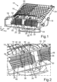
- Fig. 1 shows a radiator arrangement 10 for a vehicle 12, which is very schematically shown in Fig. 6 .
- the radiator arrangement 10 comprises a radiator 14 which can better be seen in a section view of the radiator arrangement 10 shown in Fig. 5 than in Fig. 1 .
- the radiator arrangement 10 further comprises an air guiding element 16 for guiding an airflow towards the radiator 14.
- the air guiding element 16 comprises a housing 18 which has an inlet 20 for letting in the airflow and an outlet 22 facing the radiator.
- the outlet 22 can be better seen from Fig. 5 than from Fig. 1 .
- the air guiding element 16, in particular the housing 18, is fixed to a holding frame 24 of the radiator arrangement 10, wherein the holding frame 24 holds the radiator 14.
- the air guiding element 16 and in particular the housing 18 can be directly fixed to the radiator 14.
- the housing 18 of the air guiding element 16 assures that the airflow entering the air guiding element 16 through the inlet 20 is guided substantially leakage-free towards a front face 26 (see Fig. 5 ) of the radiator 14.
- a cross-sectional area of the outlet 22 corresponds to an area of the front face 26 of the radiator 14.
- the size of the cross-sectional area of the outlet 22 is substantially the same as the size of the front face 26 of the radiator 14. Consequently, the air guiding element 16 ensures a very efficient guiding of the airflow towards the front face 26 of the radiator 14 such that the airflow can further pass through the radiator 14. As a result, heat transfer between the air passing through the radiator 14 and a cooling fluid, in particular a cooling liquid, flowing through pipes or conduits of the radiator 14 can take place.
- the air guiding element 16 comprises a plurality of louvers 28, 30, which are in the embodiment shown in Fig. 1 and Fig. 2 arranged at the inlet 20 of the air guiding element 16.
- the louvers 28, 30 are provided with reference signs in Fig. 1 and in Fig. 2 .
- the louvers 28, 30 are configured and arranged in order to prevent stones of a predetermined size to hit the radiator 14.
- the louvers 28, 30 do not constitute a separate component or part which needs to be fixed to the radiator 14 such as it would be the case for a separate stone protection grill. Rather, by fixing the air guiding element 16 to the radiator 14 or to the holding frame 24, the louvers 28, 30 fulfil their function of providing a stone chip protection for the radiator 14.
- the louvers 28, 30 are made in one piece with a housing 18 of the air guiding element 16.
- the housing 18 of the air guiding element 16 can in particular be manufactured by injection molding of plastic. In this injection molding process, the louvers 28, 30 can be readily formed integrally with the other components of the air guiding element 16.
- louvers 28, 30 are fixed in position relative to the housing 18, the louvers 28, 30 permanently fulfil their function of preventing stones from getting to or hitting the radiator 14. This is the case, even if there is no further stone chip protection element included into the radiator arrangement 10.
- the louvers 28, 30 are configured as plate like elements having a narrow side or front edge 32 facing the airflow entering the inlet 20.
- upper faces 34 and lower faces 36 of the louvers 28, 30 are oriented substantially parallel to the airflow entering the inlet 20 in operation of the radiator arrangement 10.
- louvers 28, 30 Due to this preferred shape of the louvers 28, 30 and even though the louvers 28, 30 are immobile, the louvers 28, 30 only cause a very small pressure loss in operation of the radiator arrangement 10. In other words, the shape and arrangement of the louvers 28, 30 impedes the airflow only to a little extent. Consequently, the airflow can reach the front face 26 of the radiator 14 to a particularly large extent without a substantial pressure loss. This is beneficial for a good heat transfer from the cooling fluid, in particular cooling liquid, flowing through pipes or conduits of the radiator 14 in operation of the radiator arrangement 10.
- the louvers 28, 30 extend substantially in a width direction of the inlet 20.
- this width direction is preferably substantially parallel to a vehicle transverse axis y.
- a height direction of the inlet 20 preferably extends substantially parallel to a vertical axis z of the vehicle 12.
- the vehicle transverse axis y, the vehicle vertical axis z and a vehicle longitudinal axis x are illustrated by a respective coordinate system indicated in Fig. 1 , in Fig. 5 and in Fig. 6 .
- the louvers 28, 30 which prevent stones of a predetermined size from hitting the radiator 14 can extend substantially in the height direction of the inlet 20.
- a width of the inlet 20 is larger than a height of the inlet 20.
- a center strut 38 is provided.
- the center strut 38 divides the inlet 20 into a first inlet portion 40 and a second inlet portion 42 (see Fig. 2 ).
- a first group of the louvers 28, 30, for example the louvers 28 are arranged within the first inlet portion 40.
- a second group of the louvers 28, 30, for example the louvers 30, are arranged within the second inlet portion 42.
- the first group of louvers 28 can comprise stabilizing ribs 44 extending substantially in the height direction of the inlet 20.
- These stabilizing ribs 44 have end portions 50, 52 abutting a frame element 54 of the inlet.
- end portions 50, 52 of the ribs 44 are provided with reference signs in Fig. 1 and Fig. 2 .
- the louvers 30 arranged within the second inlet portion 42 are also stabilized by stabilizing ribs 56.
- the stabilizing ribs 56 are provided with a reference sign in Fig. 1 and in Fig. 2 , respectively for reasons of clarity.
- the stabilizing ribs 56 arranged within the second inlet portion 42 each comprise end portions abutting the frame element 54.
- the stabilizing ribs 44, 56 are made integrally, i.e. in one piece, with the housing 18 of the air guiding element 16, preferably in the injection molding process.
- a cross-sectional area of the inlet 20 is smaller than the cross-sectional area of the outlet 22 of the air guiding element 16.
- the corresponding flat and broad shape of the inlet 20 is also visible from the front side view of the radiator arrangement 10 shown in Fig. 3 .
- the radiator arrangement 10 also comprises a shutter assembly 58 which is arranged at the air guiding element 16. Specifically, the shutter assembly 58 is arranged at the inlet 20 of the air guiding element 16, upstream of the immobile louvers 28, 30.
- the shutter assembly 58 which is preferably contacting the inlet 20 of the air guiding element 16 in a substantially leakage-free manner, can in particular be fixed to a front-end structure of the vehicle 12.
- the front-end structure which can in particular comprise a frame like element holding the shutter assembly 58 in place, is not shown in Fig. 3 for reasons of clarity.
- the shutter assembly 58 also comprises a plurality of louvers 60.
- these louvers 60 are not fixed in position or immobile as is the case for the louvers 28, 30 made in one piece with the housing 18. Rather, the louvers 60 of the shutter assembly 58 are movable with respect to a frame structure 62 of the shutter assembly 58.
- the frame structure 62 is fixed to the frame element 54 of the air guiding element 16 in order to arrange the shutter assembly 58 at the inlet 20 of the air guiding element 16.
- a mechanism 64 for moving the movable louvers 60 into their various positions is schematically shown in Fig. 3 .
- This mechanism 64 is arranged in front of the center strut 38.
- the mechanism 64 is configured to rotate the blade-like louvers 60 of the shutter assembly 58 in order to influence the amount of air that can enter the inlet 20 and then further be guided to the radiator 14 by means of the housing 18 of the air guiding element 16.
- the movable louvers 60 substantially extend in the same direction as the immobile louvers 28, 30 or louvers 28, 30 fixed in position relative to the housing 18 of the air guiding element 16.
- the immobile louvers 28, 30 extend substantially in the height direction of the inlet 20 as shown in Fig. 4
- the orientation of the immobile louvers 28, 30 can be different from the orientation of the movable louvers 60.
- movable louvers 60 are shown moved into an open position allowing a maximum airflow to pass through the shutter assembly 58 and therefore further through the inlet 20 towards the radiator 14.
- this orientation of the movable louvers 60 at least some of the louvers 28, 30 fixed in position are in alignment with a space between two adjacent movable louvers 60.
- the fixed or immobile louvers 28, 30 can in particular be arranged between two adjacent movable louvers 60 moved into the open position. Such an arrangement is particularly effective in order to prevent stones from entering the air guiding element. This is due to the fact that the fixed or immobile louvers 28, 30 in cooperation with the movable louvers 60 efficiently prevent the stones from getting into the housing 18 and therefore from hitting the radiator 14.
- the arrangement of the fixed louvers 28, 30 and/or the movable louvers 60 can, in particular, be such that at least about 70 % of stones having a diameter of 12 mm are prevented from getting to the radiator 14.
- the radiator 14 can be inclined, in particular at an angle of about 45°, with respect to a plane determined by the height direction and the width direction of the inlet 20. Due to this inclination of the radiator 14, a lower edge 66 of the radiator 14 in the height direction is closer to the inlet 20 than an upper edge 68 of the radiator 14. As a consequence of the inclined orientation of the radiator 14, a space 70 is provided above the housing 18 of the air guiding element 16 (see Fig. 5 ). This space 70 can be advantageously utilized in the vehicle 12, for example for storing items of passengers of the vehicle 12.
- Fig. 5 further shows that a further heat exchanger, i.e. another heat exchanger than the radiator 14, can be part of the radiator arrangement 10.
- the radiator arrangement 10 can comprise a further heat exchanger configured as a condenser 72 of an air conditioning system of the vehicle 12.
- this condenser 72 is arranged downstream of the radiator 14 with respect to the direction of the airflow, when the airflow passes through the radiator 14.
- the area of the front face 26 of the radiator 14 can be smaller than the cross-sectional area of the outlet 22.
- the outlet 22 has a cross-sectional area encompassing the area of the front face 26 of the radiator 14.
- the cross-sectional area of the outlet 22 preferably corresponds to an area of a front face of the condenser 72.
- Fig. 5 further schematically shows a fan 74 which can be arranged further downstream of the radiator 14 and of the condenser 72.
- blades of the fan 74 which are not shown in detail in Fig. 5 , can rotate about a rotation axis 76 of the fan 74 or cooling fan in order to cause the air entering the inlet 20 of the housing 18 to flow through further through the housing 18 and then through the radiator 14.
- the vehicle 12 having the radiator arrangement 10 is schematically shown in a side view.
- the inclined position of the radiator 14 is illustrated even though the representation of the inclination is not realistic in terms of the actual arrangement of the radiator 14 within the vehicle 12 nor in terms of the actual size of the radiator arrangement 10.
- the radiator arrangement 10 is preferably located in a front-end portion 78 of the vehicle 12.
- the inlet 20 of the radiator arrangement 10 can be located or arranged behind a decorative grill 80 of the vehicle 12 which is indicated only schematically in Fig. 6 .
- the air passing through the decorative grill 80 is then further introduced into the inlet 20 of the air guiding element 16 which is part of the radiator arrangement 10. If such a decorative grill 80 is present, the decorative grill 80 further contributes in preventing stones from getting to the front face 26 of the radiator 14.
- the decorative grill 80 forms in particular part of an external surface of the vehicle 12.
Landscapes
- Engineering & Computer Science (AREA)
- Chemical & Material Sciences (AREA)
- Combustion & Propulsion (AREA)
- Transportation (AREA)
- Mechanical Engineering (AREA)
- Cooling, Air Intake And Gas Exhaust, And Fuel Tank Arrangements In Propulsion Units (AREA)
Claims (13)
- Agencement de radiateur pour un véhicule (12), comprenant un radiateur (14) et un élément guide d'air (16) pour guider un flux d'air vers le radiateur (14), dans lequel l'élément de guidage d'air (16) présente une entrée (20) pour laisser entrer le flux d'air et une sortie (22) faisant face au radiateur (14) et dans lequel l'élément de guidage d'air (16) comprend une pluralité de persiennes (28, 30) qui sont configurées pour empêcher des pierres d'une taille prédéterminée de heurter le radiateur (14),dans lequel les persiennes (28, 30) sont fixées en position par rapport à un boîtier (18) de l'élément guide d'air (16), dans lequel le boîtier (18) est configuré pour guider le flux d'air vers la sortie (22), dans lequel la sortie (22) présente une aire de section transversale englobant au moins une aire d'une face avant (26) du radiateur (14), dans lequel la face avant (26) du radiateur (14) est exposée au flux d'air et dans lequel l'agencement de radiateur (10) comprend un ensemble volet (58),caractérisé en ce quel'ensemble volet (58) est agencé au niveau de l'entrée (20) de l'élément de guide (16), dans lequel l'ensemble volet (58) comprend une pluralité de persiennes (60) qui sont mobiles par rapport à une structure de cadre (62) de l'ensemble volet (58), dans lequel la structure de cadre (62) est fixée à un élément de cadre (54) de l'élément guide d'air (16), dans lequel l'élément de guidage d'air (16) comprend une entretoise centrale (38) divisant l'entrée (20) en une première partie d'entrée (40) et une seconde partie d'entrée (42), dans lequel un premier groupe de persiennes (28) est agencé à l'intérieur de la première partie d'entrée (40) et un second groupe de persiennes (30) est agencé à l'intérieur de la seconde partie d'entrée (42), dans lequel l'agencement de radiateur (10) comprend un mécanisme (64) pour déplacer les persiennes mobiles (60) dans leurs diverses positions et dans lequel le mécanisme (64) est agencé devant l'entretoise centrale (38).
- Agencement de radiateur selon la revendication 1,
caractérisé en ce que
les persiennes (28, 30) sont configurées sous la forme d'éléments semblables à une plaque présentant un côté étroit (32) faisant face au flux d'air et des faces supérieure et inférieure (34, 36) qui sont orientées sensiblement parallèlement au flux d'air. - Agencement de radiateur selon l'une quelconque des revendications précédentes, caractérisé en ce que
les persiennes (28, 30) sont réalisées, en particulier par moulage par injection de matière plastique, d'une seule pièce avec le boîtier (18) de l'élément guide d'air (16). - Agencement de radiateur selon l'une quelconque des revendications précédentes, caractérisé en ce que
l'élément guide d'air (16) est fixé d'une manière pratiquement sans fuite au radiateur (14) et/ou à un cadre de maintien (24) maintenant le radiateur (14). - Agencement de radiateur selon l'une quelconque des revendications précédentes, caractérisé en ce que
les persiennes (28, 30) s'étendent dans une direction de largeur (y) de l'entrée (20) et/ou dans une direction de hauteur (z) de l'entrée (20). - Agencement de radiateur selon l'une quelconque des revendications précédentes, caractérisé en ce que
le premier groupe de persiennes (28) et le second groupe de persiennes (30) comprennent chacun au moins une nervure de stabilisation (44, 56) s'étendant dans une première direction (z) qui est différente d'une seconde direction (y) dans laquelle les persiennes (28, 30) du groupe respectif s'étendent, dans lequel la au moins une nervure de stabilisation (44, 56) présente des parties d'extrémité (50, 52) venant en butée contre l'élément de cadre (54) de l'entrée. - Agencement de radiateur selon l'une quelconque des revendications précédentes, caractérisé en ce que
une aire de section transversale de l'entrée (20) est plus petite que l'aire de section transversale de la sortie (22). - Agencement de radiateur selon l'une quelconque des revendications précédentes, caractérisé en ce que
les persiennes mobiles (60) de l'ensemble volet (58) s'étendent sensiblement dans la même direction (y) que les persiennes (28, 30) fixées en position par rapport au boîtier (18) de l'élément guide d'air (16). - Agencement de radiateur selon l'une quelconque des revendications précédentes, caractérisé en ce que
lorsque les persiennes mobiles (60) de l'ensemble volet (58) sont déplacées dans une position ouverte permettant à un flux d'air maximum de passer à travers l'ensemble volet (58), au moins certaines des persiennes (28, 30) fixées en position par rapport au boîtier (18) de l'élément guide d'air (16) sont alignées sur un espace entre deux persiennes mobiles adjacentes (60). - Agencement de radiateur selon l'une quelconque des revendications précédentes, caractérisé en ce que
par rapport au flux d'air, les persiennes mobiles (60) de l'ensemble volet (58) sont agencées en amont des persiennes (28, 30) fixées en position par rapport au boîtier (18) de l'élément guide d'air (16). - Agencement de radiateur selon l'une quelconque des revendications précédentes, caractérisé en ce que
les persiennes (28, 30, 60) sont configurées pour empêcher des pierres présentant une taille d'au moins 15 mm, de préférence d'au moins 12 mm, de heurter le radiateur (14). - Agencement de radiateur selon l'une quelconque des revendications précédentes, caractérisé en ce que
le radiateur (14) est incliné, en particulier selon un angle d'environ 45°, par rapport à un plan déterminé par une direction en hauteur (z) et une direction en largeur (y) de l'entrée (20), dans lequel un bord inférieur (66) du radiateur (14) dans la direction de hauteur (z) est plus proche de l'entrée (20) qu'un bord supérieur (68) du radiateur (14). - Véhicule équipé d'un agencement de radiateur (10) selon l'une quelconque des revendications précédentes, dans lequel l'agencement de radiateur (10) est situé dans une partie d'extrémité avant (78) du véhicule (12), en particulier derrière une calandre décorative (80) du véhicule (12), dans lequel la grille décorative (80) est agencée au niveau de la partie d'extrémité avant (78) du véhicule (12).
Priority Applications (4)
| Application Number | Priority Date | Filing Date | Title |
|---|---|---|---|
| EP21203347.6A EP4169755B1 (fr) | 2021-10-19 | 2021-10-19 | Agencement de radiateur pour véhicule et véhicule |
| PCT/EP2022/075422 WO2023066571A1 (fr) | 2021-10-19 | 2022-09-13 | Agencement de radiateur pour véhicule, et véhicule |
| CN202280070187.5A CN118119519A (zh) | 2021-10-19 | 2022-09-13 | 用于车辆的散热器布置结构和车辆 |
| US18/689,243 US12611924B2 (en) | 2021-10-19 | 2022-09-13 | Radiator arrangement for a vehicle and vehicle |
Applications Claiming Priority (1)
| Application Number | Priority Date | Filing Date | Title |
|---|---|---|---|
| EP21203347.6A EP4169755B1 (fr) | 2021-10-19 | 2021-10-19 | Agencement de radiateur pour véhicule et véhicule |
Publications (2)
| Publication Number | Publication Date |
|---|---|
| EP4169755A1 EP4169755A1 (fr) | 2023-04-26 |
| EP4169755B1 true EP4169755B1 (fr) | 2024-12-11 |
Family
ID=78528619
Family Applications (1)
| Application Number | Title | Priority Date | Filing Date |
|---|---|---|---|
| EP21203347.6A Active EP4169755B1 (fr) | 2021-10-19 | 2021-10-19 | Agencement de radiateur pour véhicule et véhicule |
Country Status (4)
| Country | Link |
|---|---|
| US (1) | US12611924B2 (fr) |
| EP (1) | EP4169755B1 (fr) |
| CN (1) | CN118119519A (fr) |
| WO (1) | WO2023066571A1 (fr) |
Families Citing this family (4)
| Publication number | Priority date | Publication date | Assignee | Title |
|---|---|---|---|---|
| EP4169755B1 (fr) * | 2021-10-19 | 2024-12-11 | Audi AG | Agencement de radiateur pour véhicule et véhicule |
| US20250060177A1 (en) * | 2023-08-15 | 2025-02-20 | Valeo Systemes Thermiques | Stone guard |
| US20250060125A1 (en) * | 2023-08-15 | 2025-02-20 | Valeo Systemes Thermiques | Heat exchanger module |
| FR3161263A1 (fr) * | 2024-04-15 | 2025-10-17 | Valeo Systemes Thermiques | Ensemble comportant un conduit de prise d’air, et une grille de protection |
Family Cites Families (46)
| Publication number | Priority date | Publication date | Assignee | Title |
|---|---|---|---|---|
| DE10047138B4 (de) * | 2000-09-22 | 2014-07-10 | General Motors Llc ( N. D. Ges. D. Staates Delaware ) | Kühlgebläsesystem für ein Fahrzeug mit Brennstoffzellenantrieb sowie ein Verfahren zum Betrieb eines Brennstoffzellensystems |
| US8161919B2 (en) * | 2008-12-08 | 2012-04-24 | Webasto Ag | Variable vent system integrated into a vehicle front end grill |
| US20110005732A1 (en) * | 2009-07-10 | 2011-01-13 | Keihin Corporation | Vehicular air conditioning apparatus |
| IN2012DN01851A (fr) * | 2009-09-03 | 2015-08-21 | Honda Motor Co Ltd | |
| FR2950574B1 (fr) * | 2009-09-29 | 2012-03-23 | Valeo Systemes Thermiques | Bloc d'echange thermique pour vehicule automobile |
| JP5620085B2 (ja) | 2009-10-26 | 2014-11-05 | 富士重工業株式会社 | 可変ダクト装置 |
| US8720529B2 (en) * | 2009-12-11 | 2014-05-13 | Keihin Corporation | Heat exchanger having a partition member for use in a vehicular air conditioning apparatus, and a vehicular air conditioning apparatus including the heat exchanger |
| JP5298241B2 (ja) * | 2010-07-08 | 2013-09-25 | 本田技研工業株式会社 | 車両のシャッタの開閉制御装置 |
| CN103167965B (zh) * | 2010-09-27 | 2016-02-10 | Srg环球公司 | 用于交通工具格栅的遮板系统 |
| KR101601050B1 (ko) * | 2010-10-06 | 2016-03-22 | 현대자동차주식회사 | 차량용 냉각장치 |
| JP5799792B2 (ja) * | 2011-01-07 | 2015-10-28 | 株式会社デンソー | 冷媒放熱器 |
| US8544581B2 (en) * | 2011-04-04 | 2013-10-01 | Srg Global, Inc. | Drive system for multiple movable systems |
| DE202011050032U1 (de) | 2011-05-04 | 2011-07-25 | Dr. Schneider Kunststoffwerke Gmbh | Drosseleinrichtung für den Luftdurchsatz durch einen Luftdurchlass |
| US8631889B2 (en) * | 2011-06-20 | 2014-01-21 | David Begleiter | Combined condensation radiator fan module and brake cooling duct shutter system |
| CH706456B1 (de) * | 2012-04-30 | 2016-03-15 | Schwanden Kunststoff | Jalousie für die Anordnung vor einem Kühler. |
| US9879589B2 (en) * | 2012-08-06 | 2018-01-30 | GM Global Technology Operations LLC | Initialization sequence for a vehicle grille shutter |
| US10029558B2 (en) * | 2013-03-15 | 2018-07-24 | Srg Global, Inc. | Grille shutter assembly |
| JP2016537258A (ja) * | 2013-11-23 | 2016-12-01 | ダイムラー・アクチェンゲゼルシャフトDaimler AG | 自動車用のラジエータグリルレイアウト |
| DE102013113489A1 (de) * | 2013-12-04 | 2015-06-11 | Dr. Ing. H.C. F. Porsche Aktiengesellschaft | Verschließbare Luftleiteinrichtung an einem Fahrzeug |
| KR102019044B1 (ko) | 2013-12-18 | 2019-09-06 | 현대자동차 주식회사 | 자동차의 기류 유도 장치 |
| JP2015214211A (ja) * | 2014-05-09 | 2015-12-03 | アイシン精機株式会社 | 車両用グリル装置 |
| JP6036752B2 (ja) * | 2014-06-24 | 2016-11-30 | トヨタ自動車株式会社 | 車両およびその制御方法 |
| KR101532976B1 (ko) * | 2014-09-01 | 2015-07-01 | 현대모비스 주식회사 | 차량용 에어 플랩 장치 |
| ES2774464T3 (es) * | 2015-07-31 | 2020-07-21 | Weidplas Gmbh | Conjunto de trampillas de ventilación para un vehículo |
| KR101694058B1 (ko) * | 2015-09-11 | 2017-01-09 | 현대자동차주식회사 | 차량의 외장형 액티브 에어플랩 장치 |
| FR3042458B1 (fr) * | 2015-10-15 | 2018-07-13 | Valeo Systemes Thermiques | Dispositif de contrôle d'entrée d'air avec actionneur déporté |
| US20180370348A1 (en) * | 2015-12-09 | 2018-12-27 | Denso Corporation | Cooling device |
| FR3047205B1 (fr) * | 2016-02-03 | 2018-01-26 | Valeo Systemes Thermiques | Dispositif d'obturation d'entree d'air de face avant de vehicule automobile et son procede de fabrication |
| FR3050146B1 (fr) * | 2016-04-18 | 2019-04-19 | Valeo Systemes Thermiques | Dispositif de rafraichissement d'air pour vehicule et installation de chauffage, de ventilation et/ou de climatisation associee |
| KR101836652B1 (ko) * | 2016-06-16 | 2018-03-08 | 현대자동차주식회사 | 배터리 열해방지를 위한 인캡슐레이션 구조 및 그 작동방법 |
| FR3053008B1 (fr) * | 2016-06-28 | 2019-04-05 | Valeo Systemes Thermiques | Systeme de gestion d’entree d’air pour face avant de vehicule automobile et structure d’un tel systeme |
| JP6455557B2 (ja) * | 2017-06-30 | 2019-01-23 | マツダ株式会社 | 自動車のグリルシャッタ取付構造 |
| US10071625B1 (en) * | 2017-08-15 | 2018-09-11 | Ford Global Technologies, Llc | Flow control assembly and method utilizing apertured shutters |
| CN109779733A (zh) * | 2017-11-14 | 2019-05-21 | 福特环球技术公司 | 具有经由可移动叶片的冷却剂路径的车辆散热器组件 |
| FR3076496B1 (fr) * | 2018-01-05 | 2020-05-22 | Valeo Systemes Thermiques | Guide d'air pour module de face avant pour vehicule automobile |
| EP3591328B1 (fr) * | 2018-07-03 | 2022-08-17 | Valeo Autosystemy Sp. z o.o. | Module d'échangeur de chaleur avec grille de protection servant à diriger et à distribuer de l'air |
| DE102018211996A1 (de) * | 2018-07-18 | 2020-01-23 | Röchling Automotive SE & Co. KG | Luftklappenvorrichtung mit integrierten Lichtleitern für ein Kraftfahrzeug |
| FR3085891B1 (fr) * | 2018-09-17 | 2022-09-02 | Valeo Systemes Thermiques | Module d’echange thermique pour vehicule automobile |
| FR3094674B1 (fr) * | 2019-04-03 | 2021-04-16 | Flex N Gate France | Dispositif d’aération pour un véhicule, procédé de montage associé |
| JP7388030B2 (ja) * | 2019-07-26 | 2023-11-29 | 株式会社デンソー | 車両のシャッタ装置 |
| JP7693659B2 (ja) * | 2019-11-26 | 2025-06-17 | アドヴァル テク ホールディング アーゲー | モータビークル用のラジエータシャッター |
| FR3104496B1 (fr) * | 2019-12-13 | 2022-08-05 | Valeo Systemes Thermiques | Module de refroidissement de véhicule automobile |
| DE102020131530B3 (de) * | 2020-11-27 | 2021-10-14 | Montaplast Gesellschaft mit beschränkter Haftung | Luftführungssteuerung |
| KR102922354B1 (ko) * | 2021-06-29 | 2026-02-03 | 현대자동차주식회사 | 차량용 액티브 듀얼 롤 셔터장치 |
| US12365236B2 (en) * | 2021-08-31 | 2025-07-22 | Aero18, Llc | Variably openable fairing with collapsible panels |
| EP4169755B1 (fr) * | 2021-10-19 | 2024-12-11 | Audi AG | Agencement de radiateur pour véhicule et véhicule |
-
2021
- 2021-10-19 EP EP21203347.6A patent/EP4169755B1/fr active Active
-
2022
- 2022-09-13 CN CN202280070187.5A patent/CN118119519A/zh active Pending
- 2022-09-13 WO PCT/EP2022/075422 patent/WO2023066571A1/fr not_active Ceased
- 2022-09-13 US US18/689,243 patent/US12611924B2/en active Active
Also Published As
| Publication number | Publication date |
|---|---|
| EP4169755A1 (fr) | 2023-04-26 |
| US20240399855A1 (en) | 2024-12-05 |
| CN118119519A (zh) | 2024-05-31 |
| WO2023066571A1 (fr) | 2023-04-27 |
| US12611924B2 (en) | 2026-04-28 |
Similar Documents
| Publication | Publication Date | Title |
|---|---|---|
| EP4169755B1 (fr) | Agencement de radiateur pour véhicule et véhicule | |
| CN1957165B (zh) | 冷却系统 | |
| US7603968B2 (en) | Cooling system | |
| JP6656170B2 (ja) | エアガイド及びエアガイドモジュール | |
| US20060254838A1 (en) | Cooling device for use on a vehicle | |
| US20060211364A1 (en) | Cooling system for motor vehicles and method for controlling at least one air mass flow through a radiator | |
| US11260743B2 (en) | Air flow regulating device for an air inlet of a motor vehicle front-end module | |
| US10059193B2 (en) | Grille for a vehicle, in particular a commercial vehicle as well as a vehicle | |
| US11725569B1 (en) | Air duct for water ingress management in a vehicle | |
| CN109414985B (zh) | 增压空气阻挡板 | |
| KR20190012363A (ko) | 차량용 그릴 | |
| US20030019606A1 (en) | Cooling module with air dams | |
| KR101693348B1 (ko) | 액티브 에어 플랩 | |
| US9139068B2 (en) | Mix door and vehicle air conditioner using the same | |
| US12187113B2 (en) | Ventilation device module for a motor vehicle cooling module, ventilation device comprising such a module, and cooling module for a motor vehicle comprising such a ventilation device | |
| JP2015081705A (ja) | 冷却システム | |
| KR102629657B1 (ko) | 자동차용 열 교환기 모듈 | |
| CN108791537B (zh) | 用于机动车辆的后扰流器组件 | |
| CN117396351A (zh) | 用于电动或混合动力机动车辆的、具有带可变鼓风机壳体的切向流涡轮机的冷却模块 | |
| CN116635263B (zh) | 用于电动或混合动力机动车辆的具有切向流涡轮机的冷却模块 | |
| US20030047365A1 (en) | Fluid inlet grille with novel aerodynamic grill bars | |
| CN120187598A (zh) | 具有切向流涡轮机的用于电动或混合动力机动车辆的冷却模块的歧管壳体 | |
| US20210268978A1 (en) | Front end part | |
| US12344086B2 (en) | Cooling module for a motor vehicle comprising a tangential flow turbomachine | |
| ES2944714T3 (es) | Componente de guarnición de un vehículo y vehículo que comprende un componente de guarnición de este tipo |
Legal Events
| Date | Code | Title | Description |
|---|---|---|---|
| PUAI | Public reference made under article 153(3) epc to a published international application that has entered the european phase |
Free format text: ORIGINAL CODE: 0009012 |
|
| STAA | Information on the status of an ep patent application or granted ep patent |
Free format text: STATUS: THE APPLICATION HAS BEEN PUBLISHED |
|
| AK | Designated contracting states |
Kind code of ref document: A1 Designated state(s): AL AT BE BG CH CY CZ DE DK EE ES FI FR GB GR HR HU IE IS IT LI LT LU LV MC MK MT NL NO PL PT RO RS SE SI SK SM TR |
|
| STAA | Information on the status of an ep patent application or granted ep patent |
Free format text: STATUS: REQUEST FOR EXAMINATION WAS MADE |
|
| 17P | Request for examination filed |
Effective date: 20231026 |
|
| RBV | Designated contracting states (corrected) |
Designated state(s): AL AT BE BG CH CY CZ DE DK EE ES FI FR GB GR HR HU IE IS IT LI LT LU LV MC MK MT NL NO PL PT RO RS SE SI SK SM TR |
|
| GRAP | Despatch of communication of intention to grant a patent |
Free format text: ORIGINAL CODE: EPIDOSNIGR1 |
|
| STAA | Information on the status of an ep patent application or granted ep patent |
Free format text: STATUS: GRANT OF PATENT IS INTENDED |
|
| INTG | Intention to grant announced |
Effective date: 20240718 |
|
| GRAS | Grant fee paid |
Free format text: ORIGINAL CODE: EPIDOSNIGR3 |
|
| P01 | Opt-out of the competence of the unified patent court (upc) registered |
Free format text: CASE NUMBER: APP_46467/2024 Effective date: 20240809 |
|
| GRAA | (expected) grant |
Free format text: ORIGINAL CODE: 0009210 |
|
| STAA | Information on the status of an ep patent application or granted ep patent |
Free format text: STATUS: THE PATENT HAS BEEN GRANTED |
|
| AK | Designated contracting states |
Kind code of ref document: B1 Designated state(s): AL AT BE BG CH CY CZ DE DK EE ES FI FR GB GR HR HU IE IS IT LI LT LU LV MC MK MT NL NO PL PT RO RS SE SI SK SM TR |
|
| REG | Reference to a national code |
Ref country code: GB Ref legal event code: FG4D |
|
| REG | Reference to a national code |
Ref country code: CH Ref legal event code: EP |
|
| REG | Reference to a national code |
Ref country code: DE Ref legal event code: R096 Ref document number: 602021023188 Country of ref document: DE |
|
| REG | Reference to a national code |
Ref country code: IE Ref legal event code: FG4D |
|
| REG | Reference to a national code |
Ref country code: LT Ref legal event code: MG9D |
|
| PG25 | Lapsed in a contracting state [announced via postgrant information from national office to epo] |
Ref country code: HR Free format text: LAPSE BECAUSE OF FAILURE TO SUBMIT A TRANSLATION OF THE DESCRIPTION OR TO PAY THE FEE WITHIN THE PRESCRIBED TIME-LIMIT Effective date: 20241211 |
|
| PG25 | Lapsed in a contracting state [announced via postgrant information from national office to epo] |
Ref country code: FI Free format text: LAPSE BECAUSE OF FAILURE TO SUBMIT A TRANSLATION OF THE DESCRIPTION OR TO PAY THE FEE WITHIN THE PRESCRIBED TIME-LIMIT Effective date: 20241211 |
|
| PG25 | Lapsed in a contracting state [announced via postgrant information from national office to epo] |
Ref country code: BG Free format text: LAPSE BECAUSE OF FAILURE TO SUBMIT A TRANSLATION OF THE DESCRIPTION OR TO PAY THE FEE WITHIN THE PRESCRIBED TIME-LIMIT Effective date: 20241211 |
|
| REG | Reference to a national code |
Ref country code: NL Ref legal event code: MP Effective date: 20241211 |
|
| PG25 | Lapsed in a contracting state [announced via postgrant information from national office to epo] |
Ref country code: ES Free format text: LAPSE BECAUSE OF FAILURE TO SUBMIT A TRANSLATION OF THE DESCRIPTION OR TO PAY THE FEE WITHIN THE PRESCRIBED TIME-LIMIT Effective date: 20241211 |
|
| PG25 | Lapsed in a contracting state [announced via postgrant information from national office to epo] |
Ref country code: NO Free format text: LAPSE BECAUSE OF FAILURE TO SUBMIT A TRANSLATION OF THE DESCRIPTION OR TO PAY THE FEE WITHIN THE PRESCRIBED TIME-LIMIT Effective date: 20250311 |
|
| PG25 | Lapsed in a contracting state [announced via postgrant information from national office to epo] |
Ref country code: LV Free format text: LAPSE BECAUSE OF FAILURE TO SUBMIT A TRANSLATION OF THE DESCRIPTION OR TO PAY THE FEE WITHIN THE PRESCRIBED TIME-LIMIT Effective date: 20241211 Ref country code: GR Free format text: LAPSE BECAUSE OF FAILURE TO SUBMIT A TRANSLATION OF THE DESCRIPTION OR TO PAY THE FEE WITHIN THE PRESCRIBED TIME-LIMIT Effective date: 20250312 |
|
| PG25 | Lapsed in a contracting state [announced via postgrant information from national office to epo] |
Ref country code: RS Free format text: LAPSE BECAUSE OF FAILURE TO SUBMIT A TRANSLATION OF THE DESCRIPTION OR TO PAY THE FEE WITHIN THE PRESCRIBED TIME-LIMIT Effective date: 20250311 |
|
| PG25 | Lapsed in a contracting state [announced via postgrant information from national office to epo] |
Ref country code: NL Free format text: LAPSE BECAUSE OF FAILURE TO SUBMIT A TRANSLATION OF THE DESCRIPTION OR TO PAY THE FEE WITHIN THE PRESCRIBED TIME-LIMIT Effective date: 20241211 |
|
| REG | Reference to a national code |
Ref country code: AT Ref legal event code: MK05 Ref document number: 1750143 Country of ref document: AT Kind code of ref document: T Effective date: 20241211 |
|
| PG25 | Lapsed in a contracting state [announced via postgrant information from national office to epo] |
Ref country code: SM Free format text: LAPSE BECAUSE OF FAILURE TO SUBMIT A TRANSLATION OF THE DESCRIPTION OR TO PAY THE FEE WITHIN THE PRESCRIBED TIME-LIMIT Effective date: 20241211 |
|
| PG25 | Lapsed in a contracting state [announced via postgrant information from national office to epo] |
Ref country code: PL Free format text: LAPSE BECAUSE OF FAILURE TO SUBMIT A TRANSLATION OF THE DESCRIPTION OR TO PAY THE FEE WITHIN THE PRESCRIBED TIME-LIMIT Effective date: 20241211 |
|
| PG25 | Lapsed in a contracting state [announced via postgrant information from national office to epo] |
Ref country code: IS Free format text: LAPSE BECAUSE OF FAILURE TO SUBMIT A TRANSLATION OF THE DESCRIPTION OR TO PAY THE FEE WITHIN THE PRESCRIBED TIME-LIMIT Effective date: 20250411 |
|
| PG25 | Lapsed in a contracting state [announced via postgrant information from national office to epo] |
Ref country code: PT Free format text: LAPSE BECAUSE OF FAILURE TO SUBMIT A TRANSLATION OF THE DESCRIPTION OR TO PAY THE FEE WITHIN THE PRESCRIBED TIME-LIMIT Effective date: 20250411 |
|
| PG25 | Lapsed in a contracting state [announced via postgrant information from national office to epo] |
Ref country code: EE Free format text: LAPSE BECAUSE OF FAILURE TO SUBMIT A TRANSLATION OF THE DESCRIPTION OR TO PAY THE FEE WITHIN THE PRESCRIBED TIME-LIMIT Effective date: 20241211 |
|
| PG25 | Lapsed in a contracting state [announced via postgrant information from national office to epo] |
Ref country code: AT Free format text: LAPSE BECAUSE OF FAILURE TO SUBMIT A TRANSLATION OF THE DESCRIPTION OR TO PAY THE FEE WITHIN THE PRESCRIBED TIME-LIMIT Effective date: 20241211 Ref country code: RO Free format text: LAPSE BECAUSE OF FAILURE TO SUBMIT A TRANSLATION OF THE DESCRIPTION OR TO PAY THE FEE WITHIN THE PRESCRIBED TIME-LIMIT Effective date: 20241211 |
|
| PG25 | Lapsed in a contracting state [announced via postgrant information from national office to epo] |
Ref country code: SK Free format text: LAPSE BECAUSE OF FAILURE TO SUBMIT A TRANSLATION OF THE DESCRIPTION OR TO PAY THE FEE WITHIN THE PRESCRIBED TIME-LIMIT Effective date: 20241211 |
|
| PG25 | Lapsed in a contracting state [announced via postgrant information from national office to epo] |
Ref country code: CZ Free format text: LAPSE BECAUSE OF FAILURE TO SUBMIT A TRANSLATION OF THE DESCRIPTION OR TO PAY THE FEE WITHIN THE PRESCRIBED TIME-LIMIT Effective date: 20241211 |
|
| PG25 | Lapsed in a contracting state [announced via postgrant information from national office to epo] |
Ref country code: IT Free format text: LAPSE BECAUSE OF FAILURE TO SUBMIT A TRANSLATION OF THE DESCRIPTION OR TO PAY THE FEE WITHIN THE PRESCRIBED TIME-LIMIT Effective date: 20241211 |
|
| PG25 | Lapsed in a contracting state [announced via postgrant information from national office to epo] |
Ref country code: SE Free format text: LAPSE BECAUSE OF FAILURE TO SUBMIT A TRANSLATION OF THE DESCRIPTION OR TO PAY THE FEE WITHIN THE PRESCRIBED TIME-LIMIT Effective date: 20241211 |
|
| REG | Reference to a national code |
Ref country code: DE Ref legal event code: R097 Ref document number: 602021023188 Country of ref document: DE |
|
| PG25 | Lapsed in a contracting state [announced via postgrant information from national office to epo] |
Ref country code: DK Free format text: LAPSE BECAUSE OF FAILURE TO SUBMIT A TRANSLATION OF THE DESCRIPTION OR TO PAY THE FEE WITHIN THE PRESCRIBED TIME-LIMIT Effective date: 20241211 |
|
| PLBE | No opposition filed within time limit |
Free format text: ORIGINAL CODE: 0009261 |
|
| STAA | Information on the status of an ep patent application or granted ep patent |
Free format text: STATUS: NO OPPOSITION FILED WITHIN TIME LIMIT |
|
| 26N | No opposition filed |
Effective date: 20250912 |
|
| PGFP | Annual fee paid to national office [announced via postgrant information from national office to epo] |
Ref country code: DE Payment date: 20251031 Year of fee payment: 5 |
|
| PGFP | Annual fee paid to national office [announced via postgrant information from national office to epo] |
Ref country code: GB Payment date: 20251024 Year of fee payment: 5 |
|
| PGFP | Annual fee paid to national office [announced via postgrant information from national office to epo] |
Ref country code: FR Payment date: 20251024 Year of fee payment: 5 |