EP4172074B1 - Navette à rouleaux et navette à rouleaux suspendus - Google Patents
Navette à rouleaux et navette à rouleaux suspendus Download PDFInfo
- Publication number
- EP4172074B1 EP4172074B1 EP21742729.3A EP21742729A EP4172074B1 EP 4172074 B1 EP4172074 B1 EP 4172074B1 EP 21742729 A EP21742729 A EP 21742729A EP 4172074 B1 EP4172074 B1 EP 4172074B1
- Authority
- EP
- European Patent Office
- Prior art keywords
- shuttle
- roll
- rolls
- travel
- rack system
- Prior art date
- Legal status (The legal status is an assumption and is not a legal conclusion. Google has not performed a legal analysis and makes no representation as to the accuracy of the status listed.)
- Active
Links
Images







Classifications
-
- B—PERFORMING OPERATIONS; TRANSPORTING
- B65—CONVEYING; PACKING; STORING; HANDLING THIN OR FILAMENTARY MATERIAL
- B65G—TRANSPORT OR STORAGE DEVICES, e.g. CONVEYORS FOR LOADING OR TIPPING, SHOP CONVEYOR SYSTEMS OR PNEUMATIC TUBE CONVEYORS
- B65G1/00—Storing articles, individually or in orderly arrangement, in warehouses or magazines
- B65G1/02—Storage devices
- B65G1/04—Storage devices mechanical
-
- B—PERFORMING OPERATIONS; TRANSPORTING
- B65—CONVEYING; PACKING; STORING; HANDLING THIN OR FILAMENTARY MATERIAL
- B65G—TRANSPORT OR STORAGE DEVICES, e.g. CONVEYORS FOR LOADING OR TIPPING, SHOP CONVEYOR SYSTEMS OR PNEUMATIC TUBE CONVEYORS
- B65G1/00—Storing articles, individually or in orderly arrangement, in warehouses or magazines
- B65G1/02—Storage devices
- B65G1/04—Storage devices mechanical
- B65G1/0492—Storage devices mechanical with cars adapted to travel in storage aisles
-
- B—PERFORMING OPERATIONS; TRANSPORTING
- B65—CONVEYING; PACKING; STORING; HANDLING THIN OR FILAMENTARY MATERIAL
- B65G—TRANSPORT OR STORAGE DEVICES, e.g. CONVEYORS FOR LOADING OR TIPPING, SHOP CONVEYOR SYSTEMS OR PNEUMATIC TUBE CONVEYORS
- B65G1/00—Storing articles, individually or in orderly arrangement, in warehouses or magazines
- B65G1/02—Storage devices
- B65G1/04—Storage devices mechanical
- B65G1/0407—Storage devices mechanical using stacker cranes
-
- B—PERFORMING OPERATIONS; TRANSPORTING
- B65—CONVEYING; PACKING; STORING; HANDLING THIN OR FILAMENTARY MATERIAL
- B65G—TRANSPORT OR STORAGE DEVICES, e.g. CONVEYORS FOR LOADING OR TIPPING, SHOP CONVEYOR SYSTEMS OR PNEUMATIC TUBE CONVEYORS
- B65G1/00—Storing articles, individually or in orderly arrangement, in warehouses or magazines
- B65G1/02—Storage devices
- B65G1/04—Storage devices mechanical
- B65G1/0457—Storage devices mechanical with suspended load carriers
-
- B—PERFORMING OPERATIONS; TRANSPORTING
- B65—CONVEYING; PACKING; STORING; HANDLING THIN OR FILAMENTARY MATERIAL
- B65G—TRANSPORT OR STORAGE DEVICES, e.g. CONVEYORS FOR LOADING OR TIPPING, SHOP CONVEYOR SYSTEMS OR PNEUMATIC TUBE CONVEYORS
- B65G1/00—Storing articles, individually or in orderly arrangement, in warehouses or magazines
- B65G1/02—Storage devices
- B65G1/04—Storage devices mechanical
- B65G1/06—Storage devices mechanical with means for presenting articles for removal at predetermined position or level
- B65G1/065—Storage devices mechanical with means for presenting articles for removal at predetermined position or level with self propelled cars
-
- B—PERFORMING OPERATIONS; TRANSPORTING
- B65—CONVEYING; PACKING; STORING; HANDLING THIN OR FILAMENTARY MATERIAL
- B65G—TRANSPORT OR STORAGE DEVICES, e.g. CONVEYORS FOR LOADING OR TIPPING, SHOP CONVEYOR SYSTEMS OR PNEUMATIC TUBE CONVEYORS
- B65G21/00—Supporting or protective framework or housings for endless load-carriers or traction elements of belt or chain conveyors
-
- B—PERFORMING OPERATIONS; TRANSPORTING
- B65—CONVEYING; PACKING; STORING; HANDLING THIN OR FILAMENTARY MATERIAL
- B65G—TRANSPORT OR STORAGE DEVICES, e.g. CONVEYORS FOR LOADING OR TIPPING, SHOP CONVEYOR SYSTEMS OR PNEUMATIC TUBE CONVEYORS
- B65G21/00—Supporting or protective framework or housings for endless load-carriers or traction elements of belt or chain conveyors
- B65G21/08—Protective roofs or arch supports therefor
-
- B—PERFORMING OPERATIONS; TRANSPORTING
- B66—HOISTING; LIFTING; HAULING
- B66F—HOISTING, LIFTING, HAULING OR PUSHING, NOT OTHERWISE PROVIDED FOR, e.g. DEVICES WHICH APPLY A LIFTING OR PUSHING FORCE DIRECTLY TO THE SURFACE OF A LOAD
- B66F9/00—Devices for lifting or lowering bulky or heavy goods for loading or unloading purposes
- B66F9/06—Devices for lifting or lowering bulky or heavy goods for loading or unloading purposes movable, with their loads, on wheels or the like, e.g. fork-lift trucks
- B66F9/075—Constructional features or details
- B66F9/12—Platforms; Forks; Other load supporting or gripping members
- B66F9/14—Platforms; Forks; Other load supporting or gripping members laterally movable, e.g. swingable, for slewing or transverse movements
- B66F9/147—Whole unit including fork support moves relative to mast
- B66F9/149—Whole unit including fork support rotates
-
- B—PERFORMING OPERATIONS; TRANSPORTING
- B66—HOISTING; LIFTING; HAULING
- B66F—HOISTING, LIFTING, HAULING OR PUSHING, NOT OTHERWISE PROVIDED FOR, e.g. DEVICES WHICH APPLY A LIFTING OR PUSHING FORCE DIRECTLY TO THE SURFACE OF A LOAD
- B66F9/00—Devices for lifting or lowering bulky or heavy goods for loading or unloading purposes
- B66F9/06—Devices for lifting or lowering bulky or heavy goods for loading or unloading purposes movable, with their loads, on wheels or the like, e.g. fork-lift trucks
- B66F9/075—Constructional features or details
- B66F9/12—Platforms; Forks; Other load supporting or gripping members
- B66F9/18—Load gripping or retaining means
-
- B—PERFORMING OPERATIONS; TRANSPORTING
- B65—CONVEYING; PACKING; STORING; HANDLING THIN OR FILAMENTARY MATERIAL
- B65G—TRANSPORT OR STORAGE DEVICES, e.g. CONVEYORS FOR LOADING OR TIPPING, SHOP CONVEYOR SYSTEMS OR PNEUMATIC TUBE CONVEYORS
- B65G2201/00—Indexing codes relating to handling devices, e.g. conveyors, characterised by the type of product or load being conveyed or handled
- B65G2201/02—Articles
- B65G2201/0232—Coils, bobbins, rolls
Definitions
- the present invention relates to the provision of a roll shuttle and a hanging roll shuttle, in particular in connection with the operation of a shelving system and a transport system for handling rolls.
- JP 2006 160477 A A roller shuttle for transporting rollers in a shelving system is described. This contains a chassis that can be moved along rails using wheels, as well as a carriage that is mounted on the chassis in such a way that it can be moved relative to the direction of travel of the roller shuttle along a direction that runs transversely to the direction of travel of the roller shuttle. Using a load mandrel, it is possible to pivot a roller to be transported and stored essentially parallel to the base plane.
- JP 2006 160477 A discloses a roller shuttle according to the preamble of claim 1.
- roller shuttles are also known from JP H05 39107 A , JP-S48 100870 A , as well as JP2007 062973 .
- JP-S62 244803 a hanging roll shuttle for transporting rolls with a hanging frame and wheels mounted thereon to move a hanging roll shuttle along at least one hanging rail mounted above a storage level of the shelving system.
- the technical problem of the present invention is to increase the flexibility and throughput in a roller storage and transport system.
- a hanging roll shuttle with the features of patent claim 6 for transporting rolls Hanging roll shuttle, for transporting rolls along a hanging rail system, as well as to various pick-up and drop-off points by means of distribution stations which are coupled to several hanging rails, furthermore between shelving systems or within a shelving system.
- rolls can be stored and retrieved either single- or multiple-deep using a mandrel system.
- the mandrel system is provided with a
- Chain conveyors and preferably equipped with a stop to ensure orderly positioning of the rollers during transport and storage.
- the mandrel system can be designed either as a roll shuttle or as a hanging roll shuttle.
- the mandrel system is mounted on a chassis so that it can be moved and pivoted, while in the case of the hanging roll shuttle, the mandrel system is mounted on a hanging carriage that can be pushed back and forth on a guide rail.
- the rolls are positioned on the mandrel system with increasing or equal diameters towards the outside, so that the roll can be picked up and handled via a sleeve at the center of the rolls.
- the double bearing of the mandrel system i.e. displaceable along a transverse direction to the direction of travel of the chassis and pivotable relative to the suspension of the mandrel, allows the mandrel system to be handled in such a way that even when the mandrel is pivoted from one side to the opposite side of the chassis, the mandrel is always guided in such a way that it never extends beyond the sides of the chassis.
- Preferred embodiments of the present invention are given in the dependent patent claims.
- Figure 1 shows a perspective view of the roller shuttle according to the invention.
- the roller shuttle 10 for transporting rollers in a shelving system contains a chassis 12 with wheels 14-1, ..., 14-3 mounted thereon in order to move the roller shuttle along rails which are laid in a storage level of the shelving system.
- the roller shuttle 10 has a carriage 16 which is mounted on the chassis 12 in such a way that it can be moved relative to the direction of travel of the roller shuttle.
- the roller shuttle 10 can move in one plane or in several planes, whereby in the latter case the roller shuttle can be moved between different planes by means of a shuttle converter, so that a shelving system can be served even with a few roller shuttles 10.
- the roller shuttle 10 can also travel or be operated outside of a shelving system. To do this, it is placed on a travel rail outside the shelving system using a vertical transfer unit or it travels out of the shelving system using a rail extension to serve a transfer station. At this transfer station, the rollers are transferred to the shelving system or taken from the shelving system.
- the carriage 16 can be moved in such a way that the direction of travel deviates from the direction of travel of the roller shuttle 10 by a predetermined angle greater than zero, for example by an angle of 90 degrees. Accordingly, the carriage 16 can preferably be moved transversely to the direction of travel of the chassis 12.
- the carriage 16 can have a base plate 18 on which individual elements can be mounted.
- the base plate 18 is moved, for example, by means of a chain conveyor on a vertical frame of the carriage.
- An electric motor 20 can be provided for driving the carriage.
- the roller shuttle 10 also has a load mandrel 22 for transporting at least one roll to be stored.
- the load mandrel 22 is pivotably attached to the carriage 16, specifically in a plane that runs essentially parallel to the base plane of the chassis or to the storage plane of the shelving system.
- the load mandrel 22 also contains a chain conveyor 24 by means of which one or more rolls can be picked up onto the load mandrel 22 or placed back down again.
- the pivoting of the load mandrel 22 is carried out by means of suitable bearings, for example by means of two Bearing plates 26 and 28, which are securely locked to the base plate of the carriage 16 by means of struts 30 and 32.
- the load mandrel 22 can be mounted on the carriage 16 in a height-adjustable manner, and for example the height can be changed by means of a suitably driven spindle 34 relative to the base area of the chassis 12.
- a height-adjustable design of the load mandrel 22 simplifies the handling of rolls when picking up and putting down from the load mandrel 22.
- the length of the load mandrel 22 is preferably dimensioned such that it is an integer multiple of the width of the rolls to be transported.
- a stop can also be provided to secure the rolls during transport in the shelving system.
- At least one support roller and/or counter-support surface can preferably be provided on the underside of the chassis 12, by means of which tilting forces can be maintained in the rails of the shelving system when the load mandrel 22 is pivoted laterally relative to the roller shuttle 10.
- Figure 2 shows a schematic diagram to explain the operation of the Figure 1 shown roller shuttles
- the operation of the roller shuttle 10 in the shelving system can preferably be described with a coordinate system in which the direction of travel forms the X-axis, the storage direction the Y-axis, and the direction of travel in the vertical direction the Z-axis.
- the procedure can be such that a first position and a second position are defined along the guide rail in order to control the movement of the Roller shuttles 10 along the x-direction as part of the processing of the order.
- Figure 3 shows operating states during a superimposed longitudinal movement of the roller shuttle 10 in combination with a repositioning of the mandrel system 22.
- Figure 4 shows an explanation of the mode of operation of the roll shuttle 10 for storing rolls, single or multiple deep, in a stationary storage box 36 or in a mobile storage box 38.
- a further operating state of the roller shuttle 10 relates to the operation for actual storage and retrieval of rolls in the shelving system.
- the shelving system can have a stationary storage box 36 that is firmly mounted on the shelving system.
- a storage box can also be designed as a mobile storage box 38 that can be positioned relative to the roller shuttle 10 by means of running wheels parallel to and along the travel rails of the roller shuttle 10.
- the storage and retrieval of rolls takes place either in the stationary storage box 36 or in the mobile storage box 38 by means of the carriage 16 and the load mandrel 22.
- the carriage 16 is moved to the side edge of the roll shuttle 10 and at the same time the load mandrel 22 is pivoted so that it is positioned above the storage box 36 or 38.
- the height of the carriage 16 and the load mandrel 22 it can be achieved that either rolls are picked up onto the load mandrel 22 by means of the chain conveyor 24 of the load mandrel 22 or, in the opposite way, are delivered from the load mandrel 22 to the stationary storage box 36 or to the mobile storage box 38.
- the provision of mobile storage boxes 38 increases the flexibility of the storage system since it enables the storage and retrieval of rolls even when the roll shuttle 10 is not moving, provided the mobile storage box 38 is correctly moved relative to the roll shuttle 10.
- Figure 5 shows a perspective view of the roller shuttle 10 according to the invention in which rollers of different diameters are positioned on the load mandrel 22 As in Figure 5 As shown, the load mandrel 22 of the roll shuttle 10 preferably picks up rolls from the inside to the outside with increasing number of windings or with increasing diameter.
- roller shuttle 10 can be suitably provided with control boxes in which circuit electronics are provided for the operation and control of the drive and the servo motors for the operation of the load mandrel 22.
- Figure 6 shows a schematic representation of a shelving system in which the roller shuttle 10 according to the invention is used in combination with a hanging roller shuttle according to the invention.
- the Figure 6 shows similar to the Figure 4 the roller shuttle 10 according to the invention, the stationary storage box 36 and the mobile storage box 38. With regard to the explanation of these units, reference is made to the above statements on the Figure 4 referred to.
- a hanging roller shuttle can be used within the scope of the present invention.
- a support rail 40 is provided transversely to the direction of travel of the roller shuttle 10, which not only covers the travel area of the roller shuttle, but also the storage area of the storage boxes, preferably the mobile storage boxes 38, as well as a loading zone which is provided for the delivery or removal of rollers.
- the material flow from the loading zone takes place, for example, transversely to the direction of travel along the guide rail 40 to, for example, the mobile storage box 38.
- the roller shuttle 10 can then be positioned relative to the mobile storage box 38 in order to then pick up rolls to be stored or retrieved from the mobile storage box 38 and move them suitably to the stationary storage box 36.
- the material flow takes place in reverse from the stationary storage box 36 via the roller shuttle 10 to the mobile storage box. 38, by means of which it is then possible to unload along the hanging rail 40 to the loading zone.
- Figure 7 shows a schematic representation to illustrate the operation of the hanging roller shuttle according to the invention.
- a hanging roll shuttle 42 is provided for transporting rolls to a transfer station for further transport in a shelving system.
- the hanging roll shuttle 42 includes a hanging frame 44 with wheels 46-1, 46-2 mounted thereon for moving the hanging roll shuttle along the hanging rail 40 mounted on the top of a storage level of the shelving system.
- the load mandrel 48 is then attached to the hanging frame 44, by means of which rolls to be stored can be moved along the direction of travel of the hanging rail 40.
- the load mandrel 48 of the hanging frame 44 is preferably equipped with a chain conveyor in order to position rolls to be stored along the load mandrel, i.e. to either pick them up or release them.
- the load mandrel 48 preferably has a length that represents an integer multiple of the width of the rolls to be transported.
- a pivotable stop 50 can be provided on the hanging frame 44, which serves to secure rollers during transport of the hanging rail 40.
- the mobile storage box 38 can preferably be provided with a lifting device 52 in order to deliver rolls from the hanging roll shuttle 42 to the mobile storage box 38 after the storage surface of the mobile storage box 38 has been raised or to transfer them from the mobile storage box 38 to the hanging mandrel 48 of the hanging roll shuttle 42.
- Figure 8 shows a perspective view of the hanging roller shuttle 42 according to the invention with rollers of different diameters supported on the mandrel system.
- the loading mandrel of the hanging roller shuttle 42 is preferably equipped in such a way that the diameter of the rollers increases from the inside to the outside.
- the stop 50 secures the rollers against slipping off the loading mandrel during transport.
- the hanging roller shuttle 42 may also have a unit 54 in which suitable switching means and electronics for the operation of the hanging roller shuttle 42 are provided.
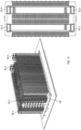
- Figure 9 shows a perspective view of the storage system according to the invention.
- the shelving system according to the invention for storing and transporting rolls has a plurality of storage levels.
- each storage level several rails run that are intended for the transport of rolls.
- a plurality of storage boxes are adjacent to the respective rails in each storage level.
- a roll shuttle 10 according to the present invention can now be moved along the rails to transport rolls.
- roller shuttle 10 is used for transport within the shelving system and the hanging roller shuttle is used for further transport between shelving systems or individual functional areas within a shelving system.
- hanging roller shuttle it is also possible to transport rollers and other stored goods to widely distributed delivery and collection stations. distribute or store from these delivery and collection stations.
- one or more lift systems 56 can preferably be provided on the front sides of the shelving system. These also enable vertical movement of the roller shuttle 10 according to the invention across several storage levels of the shelving system.
- each lift 56 serves a loading zone 58 of the shelving system, and the number of roller shuttles 10 or hanging roller shuttles 42 used in each storage level can be freely configured depending on the application.
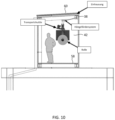
- the shelving system according to the invention also has a walk-through platform 58 to allow access to the hanging roller shuttle for maintenance or service work.
- a walk-through platform 58 to allow access to the hanging roller shuttle for maintenance or service work.
- the Figure 10 shows an example of access to a hanging roller shuttle.
- the access platform can also be accommodated in a housing 60, which allows for improved protection of the service personnel.
- the access platform is preferably arranged at a height such that the service personnel can easily access the hanging roller shuttle. This is a preferred embodiment to enable operation of shelf components, but also handling of rollers within the shelf system.
- the Figure 11 illustrates the function of the hanging roller shuttle system as a transport system between individual functional units within a shelving system.
- functional units can be formed by loading and unloading stations 62, 64, 66, the actual shelving system as in Figure 9 shown, as well as a buffer 68.
- the intermediate storage can be equipped with a pre-zone area and thus serve as a buffer for the storage and retrieval of goods and rolls in the shelving system.
- the pre-zone area can also be stocked with goods by an overhead conveyor system 70 or goods can be transported from the pre-zone area to the corresponding loading station 66.
- overhead conveyor systems according to the present invention are also suitable for connecting entire shelving systems to one another.
- the Figure 12 shows another exemplary configuration of subcomponents of the shelving system according to the present invention.
- the hanging roll shuttle 42 can also be loaded at different heights.
- a vertical lift with a receiving means 72 is used for this, which moves to a delivery station 74 in a suitable manner.
- the vertical lift 72 moves to one or more transfer stations 76, 78, which the transport shuttle 42 can drive past.
- the transport shuttle 42 then takes the rolled goods from the transfer stations 76, 78 in order to move them in the shelving system.
- the present invention enables the use of a very efficient roll shuttle or hanging roll shuttle in combination with a shelving system to achieve single and multiple depth storage of rolls.
- the handling of rolls is ensured in particular by the use of load mandrel systems.
- rolls can also be optimally moved on a hanging roll shuttle.
Landscapes
- Engineering & Computer Science (AREA)
- Mechanical Engineering (AREA)
- Transportation (AREA)
- Structural Engineering (AREA)
- Civil Engineering (AREA)
- Life Sciences & Earth Sciences (AREA)
- Geology (AREA)
- Warehouses Or Storage Devices (AREA)
Claims (15)
- Navette à rouleaux pour le transport de rouleaux dans un système de rayonnage contenant :un châssis (12) avec des roues montées sur celui-ci afin de déplacer la navette à rouleaux le long de rails de roulement qui sont posés dans un plan de stockage du système de rayonnage ;un chariot mobile (16) qui est monté au niveau du châssis (12) de sorte qu'il puisse être déplacé par rapport au sens de la marche de la navette à rouleaux le long d'un sens qui diverge du sens de la marche de la navette à rouleaux d'un angle prédéterminé supérieur à zéro ;un mandrin de charge (22) pour le transport d'au moins un rouleau à loger qui est fixé de manière pivotante au chariot mobile (16) dans un plan sensiblement parallèle au plan de stockage du système de rayonnage ; caractérisé en ce que le mandrin de charge (22) est équipé d'un transporteur à chaîne (24) afin de positionner des rouleaux à loger le long du mandrin de charge (22).
- Navette à rouleaux selon la revendication 1, dans laquelle le chariot mobile (16) est déplaçable transversalement au sens de la marche de la navette à rouleaux.
- Navette à rouleaux selon la revendication 1 ou la revendication 2, dans laquelle une butée est prévue au niveau du mandrin de charge (22) afin de fixer des rouleaux pendant un transport dans le système de rayonnage.
- Navette à rouleaux selon l'une quelconque des revendications 1 à 3, contenant un système de levage afin de lever ou d'abaisser le mandrin de charge (22) par rapport au châssis (12).
- Navette à rouleaux selon l'une quelconque des revendications 1 à 4, dans laquelle au moins un rouleau d'appui et/ou une surface d'appui antagoniste est prévu(e) au niveau du côté inférieur du châssis, au moyen duquel ou de laquelle en cas de mandrin de charge (22) pivoté latéralement par rapport à la navette à rouleaux, des forces de basculement peuvent être introduites dans les rails de roulement du système de rayonnage.
- Navette à rouleaux suspendus pour le transport de rouleaux le long d'un système de rail suspendu, ainsi qu'à des points d'alimentation et de livraison différents au moyen de postes de distribution qui sont couplés à plusieurs rails suspendus, de plus entre des systèmes de rayonnage ou à l'intérieur d'un système de rayonnage, contenant :un châssis suspendu (44) avec des roues montées sur celui-ci afin de déplacer la navette à rouleaux suspendus le long d'au moins un rail suspendu (40) qui est monté au-dessus d'un plan de stockage du système de rayonnage ;un mandrin de charge (48) fixé au châssis suspendu (44) pour le transport d'au moins un rouleau à loger le long du sens du rail suspendu (40) ; caractérisé en ce quele mandrin de charge (48) est équipé d'un transporteur à chaîne afin de positionner des rouleaux à loger le long du mandrin de charge (48).
- Navette à rouleaux suspendus selon la revendication 6,dans laquelle une butée (50) pivotante est prévue au niveau du châssis suspendu (44) afin de fixer des rouleaux pendant un transport dans le système de rayonnage et/oucontenant un système de levage afin de lever ou d'abaisser le mandrin de charge (48) par rapport au rail suspendu (40).
- Système de rayonnage pour le stockage et le transport de rouleaux contenant :au moins un plan de stockage avec au moins une paire de rails de roulement qui sont prévus pour le transport de rouleaux ;une pluralité de boîtes de stockage (36, 38) qui sont placées de manière contiguë à l'au moins une paire de rails de roulement dans le plan de stockage ;au moins une navette à rouleaux (10) selon l'une quelconque des revendications 1 à 5 qui est déplaçable le long de l'au moins une paire de rails de roulement pour le transport de rouleaux.
- Système de rayonnage selon la revendication 8, contenant au moins un
rail suspendu (40) qui est agencé transversalement au sens de la marche de l'au moins une paire de rails de roulement au-dessus du plan de stockage afin de former une voie de roulement pour une navette à rouleaux suspendus (42) selon l'une quelconque des revendications 6 et 7 au-dessus du plan de stockage. - Système de rayonnage selon la revendication 8 ou la revendication 9, dans lequel le rail suspendu est guidé dans une enceinte.
- Système de rayonnage selon l'une quelconque des revendications 8 à 10, contenant une plateforme de marche (58) afin de permettre pour des activités de maintenance ou de service un accès à l'au moins une navette à rouleaux (10) et/ou à l'au moins une navette à rouleaux suspendus (42).
- Système de rayonnage selon l'une quelconque des revendications 8 à 11, dans lequel au moins une boîte de stockage (38) qui est contiguë à l'au moins une paire de rails de roulement, peut être déplacée dans le sens de la marche de l'au moins une paire de rails de roulement.
- Système de rayonnage selon la revendication 12, dans lequel l'au moins une boîte de stockage (38) déplaçable présente un dispositif de levage (52) afin de lever ou d'abaisser une surface d'appui de la boîte de stockage (38).
- Système de rayonnage selon l'une quelconque des revendications 8 à 13, qui présente au moins deux plans de stockage, dans lequel au moins un système élévateur (56) est prévu au niveau d'au moins une surface latérale extérieure du système de rayonnage afin de mettre en place des navettes à rouleaux entre différents plans de stockage.
- Procédé de fonctionnement d'un système de rayonnage selon l'une quelconque des revendications 8 à 14, contenant les étapes suivantes :la détermination d'une première position x s 1 et d'une deuxième position x_s_2 le long de l'au moins une paire de rails de roulement afin de fixer un déplacement d'une navette à rouleaux (10) selon l'une quelconque des revendications 1 à 5 dans un premier sens le long de l'au moins une paire de rails de roulement selon un ordre de stockage ou de déstockage d'au moins un rouleau ;la commande de la position y_s du chariot de roulement transversalement au sens de la marche de la navette à rouleaux et de l'angle de pivotement α du mandrin de charge pendant le déplacement de la navette à rouleaux entre la première position x s-1 et la deuxième position x_s_2 desorte que la condition arcsin[(y_l-y_s)/L] > α(y_s) > arcsin[(y_r-y_s)/L] soit remplie lorsqueL est la longueur du mandrin de charge (22) etles valeurs yl-ys et yr-ys sont fixées à l'aide de la position y_s du chariot de roulement par rapport aux positions y_l et y_r des rails de roulement.
Priority Applications (1)
| Application Number | Priority Date | Filing Date | Title |
|---|---|---|---|
| EP24193042.9A EP4431419A3 (fr) | 2020-06-24 | 2021-06-23 | Navette à rouleaux et navette à rouleaux suspendus |
Applications Claiming Priority (2)
| Application Number | Priority Date | Filing Date | Title |
|---|---|---|---|
| DE102020207826.2A DE102020207826A1 (de) | 2020-06-24 | 2020-06-24 | Rollenshuttle und Hängerollen Shuttle |
| PCT/EP2021/067127 WO2021259993A2 (fr) | 2020-06-24 | 2021-06-23 | Navette à rouleaux et navette à rouleaux suspendus |
Related Child Applications (1)
| Application Number | Title | Priority Date | Filing Date |
|---|---|---|---|
| EP24193042.9A Division EP4431419A3 (fr) | 2020-06-24 | 2021-06-23 | Navette à rouleaux et navette à rouleaux suspendus |
Publications (3)
| Publication Number | Publication Date |
|---|---|
| EP4172074A2 EP4172074A2 (fr) | 2023-05-03 |
| EP4172074C0 EP4172074C0 (fr) | 2024-08-07 |
| EP4172074B1 true EP4172074B1 (fr) | 2024-08-07 |
Family
ID=76958911
Family Applications (2)
| Application Number | Title | Priority Date | Filing Date |
|---|---|---|---|
| EP24193042.9A Pending EP4431419A3 (fr) | 2020-06-24 | 2021-06-23 | Navette à rouleaux et navette à rouleaux suspendus |
| EP21742729.3A Active EP4172074B1 (fr) | 2020-06-24 | 2021-06-23 | Navette à rouleaux et navette à rouleaux suspendus |
Family Applications Before (1)
| Application Number | Title | Priority Date | Filing Date |
|---|---|---|---|
| EP24193042.9A Pending EP4431419A3 (fr) | 2020-06-24 | 2021-06-23 | Navette à rouleaux et navette à rouleaux suspendus |
Country Status (9)
| Country | Link |
|---|---|
| US (1) | US12486108B2 (fr) |
| EP (2) | EP4431419A3 (fr) |
| JP (1) | JP7839116B2 (fr) |
| KR (1) | KR20230026466A (fr) |
| CN (1) | CN115943112A (fr) |
| CA (1) | CA3188133A1 (fr) |
| DE (1) | DE102020207826A1 (fr) |
| ES (1) | ES2987071T3 (fr) |
| WO (1) | WO2021259993A2 (fr) |
Families Citing this family (2)
| Publication number | Priority date | Publication date | Assignee | Title |
|---|---|---|---|---|
| EP4238902A1 (fr) * | 2022-03-03 | 2023-09-06 | Jungheinrich Aktiengesellschaft | Agencement de stockage en blocs |
| CN114313804B (zh) * | 2022-03-07 | 2022-05-27 | 常州市达力塑料机械有限公司 | 一种卷用转运机构 |
Family Cites Families (26)
| Publication number | Priority date | Publication date | Assignee | Title |
|---|---|---|---|---|
| JPS5127336B2 (fr) * | 1972-03-16 | 1976-08-12 | ||
| JPS48100870A (fr) * | 1972-04-10 | 1973-12-19 | ||
| JPS571108A (en) * | 1980-06-03 | 1982-01-06 | Daifuku Co Ltd | C-hook hanger with a wire coil expansion prevention device |
| JPS5820299U (ja) * | 1981-07-31 | 1983-02-08 | 日新製鋼株式会社 | 鋼帯コイルの取出し装置 |
| JPS595504U (ja) * | 1982-06-30 | 1984-01-13 | 日本鋼管株式会社 | スリツトコイルの貯蔵装置 |
| JPS6093605U (ja) * | 1983-12-02 | 1985-06-26 | 山之内製薬株式会社 | 筒体支持具 |
| JPS62244803A (ja) * | 1986-04-16 | 1987-10-26 | Nippon Steel Corp | 中空円筒状物品の搬送・貯蔵設備 |
| DE3632237A1 (de) * | 1986-09-23 | 1988-04-07 | Focke & Co | Einrichtung zum transport von bobinen aus verpackungsmaterial in einer verpackungsmaschinenanlage |
| JPH0539107A (ja) * | 1991-07-31 | 1993-02-19 | Nippon Steel Corp | 円筒状物品の立体倉庫 |
| JP2945575B2 (ja) * | 1993-12-14 | 1999-09-06 | 日本輸送機株式会社 | フォークリフトの荷役装置 |
| US5674049A (en) * | 1994-06-17 | 1997-10-07 | Automatic Handling, Inc. | Roll handling apparatus |
| US5688009A (en) * | 1996-03-18 | 1997-11-18 | Automatic Handling, Inc. | C-hook pusher assembly |
| JP4723232B2 (ja) * | 2004-12-09 | 2011-07-13 | リンテック株式会社 | 入出庫装置 |
| JP2007062973A (ja) * | 2005-09-01 | 2007-03-15 | Sumikin Recotech Co Ltd | 立体倉庫 |
| ES2351003B1 (es) * | 2010-06-29 | 2011-08-12 | Mecalux, S.A. | Transelevador para la manipulación de paletas, dispositivo de extracción de paletas y sistema de almacenamiento de mercancías. |
| CA2838313C (fr) * | 2011-09-28 | 2018-12-18 | Dematic Accounting Services Gmbh | Systeme de stockage/recuperation automatise |
| CN204110946U (zh) * | 2014-09-29 | 2015-01-21 | 中煤建筑安装工程集团有限公司 | 一种成套式模块化悬挂胶带输送栈桥 |
| CN104358215B (zh) * | 2014-11-28 | 2016-05-11 | 中煤建筑安装工程集团有限公司 | 整体预应力全装配箱型模块式钢栈桥制作装配工艺 |
| CN105668134A (zh) | 2016-03-18 | 2016-06-15 | 中煤邯郸设计工程有限责任公司 | 一种保温走廊输送机 |
| WO2017220285A1 (fr) * | 2016-06-23 | 2017-12-28 | Amova Gmbh | Entrepôt à haut rayonnage comprenant, à l'intérieur, des transstockeurs destinés à stocker et déstocker ou transférer des marchandises entreposées |
| CN106144418A (zh) * | 2016-07-13 | 2016-11-23 | 滨海金地矿业工程技术(北京)有限公司 | 一种模块化栈桥及其施工方法 |
| CN207291995U (zh) * | 2017-08-15 | 2018-05-01 | 广州智网联运物流有限公司 | 穿梭机及索道系统 |
| CN207264125U (zh) * | 2017-08-15 | 2018-04-20 | 广州智网联运物流有限公司 | 穿梭机及其控制装置 |
| CN208007916U (zh) * | 2017-12-04 | 2018-10-26 | 广东科达洁能股份有限公司 | 一种丝饼智能分拣、包装系统 |
| WO2019213715A1 (fr) | 2018-05-11 | 2019-11-14 | Feasibility Pty Ltd | Système de tuyau de récipient modulaire |
| DE202020103095U1 (de) * | 2020-05-04 | 2020-06-05 | Rocket Solutions Gmbh | Shuttle und Regalsystem |
-
2020
- 2020-06-24 DE DE102020207826.2A patent/DE102020207826A1/de active Pending
-
2021
- 2021-06-23 ES ES21742729T patent/ES2987071T3/es active Active
- 2021-06-23 EP EP24193042.9A patent/EP4431419A3/fr active Pending
- 2021-06-23 US US18/012,890 patent/US12486108B2/en active Active
- 2021-06-23 EP EP21742729.3A patent/EP4172074B1/fr active Active
- 2021-06-23 CN CN202180052850.4A patent/CN115943112A/zh active Pending
- 2021-06-23 WO PCT/EP2021/067127 patent/WO2021259993A2/fr not_active Ceased
- 2021-06-23 KR KR1020237002179A patent/KR20230026466A/ko active Pending
- 2021-06-23 CA CA3188133A patent/CA3188133A1/fr active Pending
- 2021-06-23 JP JP2022580203A patent/JP7839116B2/ja active Active
Also Published As
| Publication number | Publication date |
|---|---|
| JP7839116B2 (ja) | 2026-04-01 |
| EP4172074A2 (fr) | 2023-05-03 |
| EP4431419A3 (fr) | 2025-03-26 |
| EP4172074C0 (fr) | 2024-08-07 |
| DE102020207826A1 (de) | 2022-02-10 |
| CA3188133A1 (fr) | 2021-12-30 |
| US20230356943A1 (en) | 2023-11-09 |
| JP2023539543A (ja) | 2023-09-15 |
| CN115943112A (zh) | 2023-04-07 |
| WO2021259993A3 (fr) | 2022-03-03 |
| US12486108B2 (en) | 2025-12-02 |
| EP4431419A2 (fr) | 2024-09-18 |
| WO2021259993A2 (fr) | 2021-12-30 |
| KR20230026466A (ko) | 2023-02-24 |
| ES2987071T3 (es) | 2024-11-13 |
Similar Documents
| Publication | Publication Date | Title |
|---|---|---|
| EP0458021B1 (fr) | Entrepôt avec rayonnages pour matériel recueilli dans des cassettes autoporteuses | |
| EP3619150B1 (fr) | Dispositif de prélèvement mobile pour un magasin à rayonnage | |
| EP3925908B1 (fr) | Système automatisé de stockage et procédé de stockage de marchandises suspendues dans ledit système de stockage | |
| EP3419926B1 (fr) | Entraînement télescopique, transtockeur comportant celui-ci et procédé de fonctionnement ainsi qu'utilisation associés | |
| EP0654425B1 (fr) | Dispositif pour emmagasiner et délivrer ou transférer des portes-charges dans un ou d'un magasin à plusieurs étages | |
| DE3725795A1 (de) | Fahrerloses foerderfahrzeug | |
| EP0589844B1 (fr) | Magasin à haute performance avec des moyens pour stocker et prélever des marchandises | |
| EP4140925B1 (fr) | Module d'automatisation, système de production, ainsi que procédé de chargement d'une machine-outil | |
| EP4431419A2 (fr) | Navette à rouleaux et navette à rouleaux suspendus | |
| DE69218116T2 (de) | Lager für Stabmaterial | |
| EP3924291B1 (fr) | Convoyeur pour porte-charges | |
| EP4174015B1 (fr) | Unité de transport de porteurs de charge avec garde au sol améliorée | |
| EP3817890B1 (fr) | Système de palettes pour le stockage et le transport de palettes pour machines-outils | |
| EP4206097A1 (fr) | Station de centrage et procede de manutention d' au moins un support de charge | |
| DE2556053A1 (de) | Hubstapler | |
| EP1357062B1 (fr) | Chariot de transport pour rayonnages d'entrepôt et entrepôt à rayonnages pour un tel chariot | |
| DE3342849C2 (fr) | ||
| DE102015115323A1 (de) | Regalbediengerät | |
| EP3251987B1 (fr) | Systeme de chargement pour marchandises au detail comprenant un dispositif de chargement transportable | |
| EP4337574A1 (fr) | Dispositif de tri | |
| DE20116805U1 (de) | Palettenübergabestation | |
| DE2626108C3 (de) | Lastaufnahmevorrichtung mit einer Verstelleinrichtung für zwei verschiedene Arten von Lastträgern am Hubschlitten eines Stapelkranes | |
| WO2022043278A1 (fr) | Ascenseur et système de rayonnage | |
| DE1908525A1 (de) | System bzw.Einrichtung zum Vorraetighalten,Handhaben,Entnehmen und Verteilen von insbesondere auf Paletten befindlichen Warenstuecken | |
| DE19528123A1 (de) | Transportvorrichtung |
Legal Events
| Date | Code | Title | Description |
|---|---|---|---|
| STAA | Information on the status of an ep patent application or granted ep patent |
Free format text: STATUS: UNKNOWN |
|
| STAA | Information on the status of an ep patent application or granted ep patent |
Free format text: STATUS: THE INTERNATIONAL PUBLICATION HAS BEEN MADE |
|
| PUAI | Public reference made under article 153(3) epc to a published international application that has entered the european phase |
Free format text: ORIGINAL CODE: 0009012 |
|
| STAA | Information on the status of an ep patent application or granted ep patent |
Free format text: STATUS: REQUEST FOR EXAMINATION WAS MADE |
|
| 17P | Request for examination filed |
Effective date: 20230124 |
|
| AK | Designated contracting states |
Kind code of ref document: A2 Designated state(s): AL AT BE BG CH CY CZ DE DK EE ES FI FR GB GR HR HU IE IS IT LI LT LU LV MC MK MT NL NO PL PT RO RS SE SI SK SM TR |
|
| DAV | Request for validation of the european patent (deleted) | ||
| DAX | Request for extension of the european patent (deleted) | ||
| GRAP | Despatch of communication of intention to grant a patent |
Free format text: ORIGINAL CODE: EPIDOSNIGR1 |
|
| STAA | Information on the status of an ep patent application or granted ep patent |
Free format text: STATUS: GRANT OF PATENT IS INTENDED |
|
| RIC1 | Information provided on ipc code assigned before grant |
Ipc: B66F 9/18 20060101ALI20240123BHEP Ipc: B65G 21/08 20060101ALI20240123BHEP Ipc: B65G 21/00 20060101ALI20240123BHEP Ipc: B66F 9/07 20060101ALI20240123BHEP Ipc: B66F 9/14 20060101ALI20240123BHEP Ipc: B65G 1/04 20060101AFI20240123BHEP |
|
| INTG | Intention to grant announced |
Effective date: 20240228 |
|
| GRAS | Grant fee paid |
Free format text: ORIGINAL CODE: EPIDOSNIGR3 |
|
| GRAA | (expected) grant |
Free format text: ORIGINAL CODE: 0009210 |
|
| STAA | Information on the status of an ep patent application or granted ep patent |
Free format text: STATUS: THE PATENT HAS BEEN GRANTED |
|
| RAP1 | Party data changed (applicant data changed or rights of an application transferred) |
Owner name: FRISSENBICHLER GESMBH |
|
| AK | Designated contracting states |
Kind code of ref document: B1 Designated state(s): AL AT BE BG CH CY CZ DE DK EE ES FI FR GB GR HR HU IE IS IT LI LT LU LV MC MK MT NL NO PL PT RO RS SE SI SK SM TR |
|
| RAP1 | Party data changed (applicant data changed or rights of an application transferred) |
Owner name: FRISSENBICHLER GESMBH Owner name: FB INDUSTRY AUTOMATION GMBH |
|
| REG | Reference to a national code |
Ref country code: GB Ref legal event code: FG4D Free format text: NOT ENGLISH |
|
| REG | Reference to a national code |
Ref country code: CH Ref legal event code: EP |
|
| REG | Reference to a national code |
Ref country code: IE Ref legal event code: FG4D Free format text: LANGUAGE OF EP DOCUMENT: GERMAN |
|
| REG | Reference to a national code |
Ref country code: DE Ref legal event code: R096 Ref document number: 502021004716 Country of ref document: DE |
|
| U01 | Request for unitary effect filed |
Effective date: 20240903 |
|
| U07 | Unitary effect registered |
Designated state(s): AT BE BG DE DK EE FI FR IT LT LU LV MT NL PT RO SE SI Effective date: 20240917 |
|
| REG | Reference to a national code |
Ref country code: ES Ref legal event code: FG2A Ref document number: 2987071 Country of ref document: ES Kind code of ref document: T3 Effective date: 20241113 |
|
| PG25 | Lapsed in a contracting state [announced via postgrant information from national office to epo] |
Ref country code: NO Free format text: LAPSE BECAUSE OF FAILURE TO SUBMIT A TRANSLATION OF THE DESCRIPTION OR TO PAY THE FEE WITHIN THE PRESCRIBED TIME-LIMIT Effective date: 20241107 |
|
| PG25 | Lapsed in a contracting state [announced via postgrant information from national office to epo] |
Ref country code: PL Free format text: LAPSE BECAUSE OF FAILURE TO SUBMIT A TRANSLATION OF THE DESCRIPTION OR TO PAY THE FEE WITHIN THE PRESCRIBED TIME-LIMIT Effective date: 20240807 Ref country code: GR Free format text: LAPSE BECAUSE OF FAILURE TO SUBMIT A TRANSLATION OF THE DESCRIPTION OR TO PAY THE FEE WITHIN THE PRESCRIBED TIME-LIMIT Effective date: 20241108 |
|
| PG25 | Lapsed in a contracting state [announced via postgrant information from national office to epo] |
Ref country code: IS Free format text: LAPSE BECAUSE OF FAILURE TO SUBMIT A TRANSLATION OF THE DESCRIPTION OR TO PAY THE FEE WITHIN THE PRESCRIBED TIME-LIMIT Effective date: 20241207 |
|
| PG25 | Lapsed in a contracting state [announced via postgrant information from national office to epo] |
Ref country code: HR Free format text: LAPSE BECAUSE OF FAILURE TO SUBMIT A TRANSLATION OF THE DESCRIPTION OR TO PAY THE FEE WITHIN THE PRESCRIBED TIME-LIMIT Effective date: 20240807 |
|
| PG25 | Lapsed in a contracting state [announced via postgrant information from national office to epo] |
Ref country code: RS Free format text: LAPSE BECAUSE OF FAILURE TO SUBMIT A TRANSLATION OF THE DESCRIPTION OR TO PAY THE FEE WITHIN THE PRESCRIBED TIME-LIMIT Effective date: 20241107 |
|
| PG25 | Lapsed in a contracting state [announced via postgrant information from national office to epo] |
Ref country code: RS Free format text: LAPSE BECAUSE OF FAILURE TO SUBMIT A TRANSLATION OF THE DESCRIPTION OR TO PAY THE FEE WITHIN THE PRESCRIBED TIME-LIMIT Effective date: 20241107 Ref country code: PL Free format text: LAPSE BECAUSE OF FAILURE TO SUBMIT A TRANSLATION OF THE DESCRIPTION OR TO PAY THE FEE WITHIN THE PRESCRIBED TIME-LIMIT Effective date: 20240807 Ref country code: NO Free format text: LAPSE BECAUSE OF FAILURE TO SUBMIT A TRANSLATION OF THE DESCRIPTION OR TO PAY THE FEE WITHIN THE PRESCRIBED TIME-LIMIT Effective date: 20241107 Ref country code: IS Free format text: LAPSE BECAUSE OF FAILURE TO SUBMIT A TRANSLATION OF THE DESCRIPTION OR TO PAY THE FEE WITHIN THE PRESCRIBED TIME-LIMIT Effective date: 20241207 Ref country code: HR Free format text: LAPSE BECAUSE OF FAILURE TO SUBMIT A TRANSLATION OF THE DESCRIPTION OR TO PAY THE FEE WITHIN THE PRESCRIBED TIME-LIMIT Effective date: 20240807 Ref country code: GR Free format text: LAPSE BECAUSE OF FAILURE TO SUBMIT A TRANSLATION OF THE DESCRIPTION OR TO PAY THE FEE WITHIN THE PRESCRIBED TIME-LIMIT Effective date: 20241108 |
|
| PG25 | Lapsed in a contracting state [announced via postgrant information from national office to epo] |
Ref country code: SM Free format text: LAPSE BECAUSE OF FAILURE TO SUBMIT A TRANSLATION OF THE DESCRIPTION OR TO PAY THE FEE WITHIN THE PRESCRIBED TIME-LIMIT Effective date: 20240807 |
|
| PG25 | Lapsed in a contracting state [announced via postgrant information from national office to epo] |
Ref country code: CZ Free format text: LAPSE BECAUSE OF FAILURE TO SUBMIT A TRANSLATION OF THE DESCRIPTION OR TO PAY THE FEE WITHIN THE PRESCRIBED TIME-LIMIT Effective date: 20240807 |
|
| PG25 | Lapsed in a contracting state [announced via postgrant information from national office to epo] |
Ref country code: SK Free format text: LAPSE BECAUSE OF FAILURE TO SUBMIT A TRANSLATION OF THE DESCRIPTION OR TO PAY THE FEE WITHIN THE PRESCRIBED TIME-LIMIT Effective date: 20240807 |
|
| PLBE | No opposition filed within time limit |
Free format text: ORIGINAL CODE: 0009261 |
|
| STAA | Information on the status of an ep patent application or granted ep patent |
Free format text: STATUS: NO OPPOSITION FILED WITHIN TIME LIMIT |
|
| 26N | No opposition filed |
Effective date: 20250508 |
|
| U20 | Renewal fee for the european patent with unitary effect paid |
Year of fee payment: 5 Effective date: 20250625 |
|
| PGFP | Annual fee paid to national office [announced via postgrant information from national office to epo] |
Ref country code: ES Payment date: 20250701 Year of fee payment: 5 |
|
| REG | Reference to a national code |
Ref country code: CH Ref legal event code: H13 Free format text: ST27 STATUS EVENT CODE: U-0-0-H10-H13 (AS PROVIDED BY THE NATIONAL OFFICE) Effective date: 20260127 |
|
| PG25 | Lapsed in a contracting state [announced via postgrant information from national office to epo] |
Ref country code: MC Free format text: LAPSE BECAUSE OF FAILURE TO SUBMIT A TRANSLATION OF THE DESCRIPTION OR TO PAY THE FEE WITHIN THE PRESCRIBED TIME-LIMIT Effective date: 20240807 |
|
| GBPC | Gb: european patent ceased through non-payment of renewal fee |
Effective date: 20250623 |
|
| REG | Reference to a national code |
Ref country code: CH Ref legal event code: K11 Free format text: ST27 STATUS EVENT CODE: U-0-0-K10-K11 (AS PROVIDED BY THE NATIONAL OFFICE) Effective date: 20260313 Ref country code: CH Ref legal event code: U11 Free format text: ST27 STATUS EVENT CODE: U-0-0-U10-U11 (AS PROVIDED BY THE NATIONAL OFFICE) Effective date: 20260313 |
|
| REG | Reference to a national code |
Ref country code: CH Ref legal event code: R17 Free format text: ST27 STATUS EVENT CODE: U-0-0-R10-R17 (AS PROVIDED BY THE NATIONAL OFFICE) Effective date: 20260318 |
|
| PG25 | Lapsed in a contracting state [announced via postgrant information from national office to epo] |
Ref country code: GB Free format text: LAPSE BECAUSE OF NON-PAYMENT OF DUE FEES Effective date: 20250623 |
|
| PG25 | Lapsed in a contracting state [announced via postgrant information from national office to epo] |
Ref country code: IE Free format text: LAPSE BECAUSE OF NON-PAYMENT OF DUE FEES Effective date: 20250623 |
|
| PG25 | Lapsed in a contracting state [announced via postgrant information from national office to epo] |
Ref country code: CH Free format text: LAPSE BECAUSE OF NON-PAYMENT OF DUE FEES Effective date: 20250630 |
|
| PGFP | Annual fee paid to national office [announced via postgrant information from national office to epo] |
Ref country code: CH Payment date: 20260313 Year of fee payment: 5 |