EP4174015A1 - Unité de transport de porteurs de charge avec garde au sol améliorée - Google Patents
Unité de transport de porteurs de charge avec garde au sol améliorée Download PDFInfo
- Publication number
- EP4174015A1 EP4174015A1 EP22203936.4A EP22203936A EP4174015A1 EP 4174015 A1 EP4174015 A1 EP 4174015A1 EP 22203936 A EP22203936 A EP 22203936A EP 4174015 A1 EP4174015 A1 EP 4174015A1
- Authority
- EP
- European Patent Office
- Prior art keywords
- conveyor unit
- conveyor
- raised
- profile
- section
- Prior art date
- Legal status (The legal status is an assumption and is not a legal conclusion. Google has not performed a legal analysis and makes no representation as to the accuracy of the status listed.)
- Granted
Links
Images


Classifications
-
- B—PERFORMING OPERATIONS; TRANSPORTING
- B66—HOISTING; LIFTING; HAULING
- B66F—HOISTING, LIFTING, HAULING OR PUSHING, NOT OTHERWISE PROVIDED FOR, e.g. DEVICES WHICH APPLY A LIFTING OR PUSHING FORCE DIRECTLY TO THE SURFACE OF A LOAD
- B66F9/00—Devices for lifting or lowering bulky or heavy goods for loading or unloading purposes
- B66F9/06—Devices for lifting or lowering bulky or heavy goods for loading or unloading purposes movable, with their loads, on wheels or the like, e.g. fork-lift trucks
- B66F9/063—Automatically guided
-
- B—PERFORMING OPERATIONS; TRANSPORTING
- B66—HOISTING; LIFTING; HAULING
- B66F—HOISTING, LIFTING, HAULING OR PUSHING, NOT OTHERWISE PROVIDED FOR, e.g. DEVICES WHICH APPLY A LIFTING OR PUSHING FORCE DIRECTLY TO THE SURFACE OF A LOAD
- B66F9/00—Devices for lifting or lowering bulky or heavy goods for loading or unloading purposes
- B66F9/06—Devices for lifting or lowering bulky or heavy goods for loading or unloading purposes movable, with their loads, on wheels or the like, e.g. fork-lift trucks
- B66F9/075—Constructional features or details
- B66F9/07513—Details concerning the chassis
Definitions
- the invention relates to a conveyor unit for conveying load carriers, and also to a conveyor device with a plurality, in particular two, of such conveyor units.
- Load carriers are regularly used for the internal transport of goods, which can be driven under by industrial trucks, lifted together with the goods stored on them and set down again at the destination after transport.
- a well-known example of such a load carrier is the standardized and reusable "Euro pallet”.
- conveyors Various forms of industrial trucks are known from the prior art, which are referred to below as conveyors.
- the former such as the EP 2 336 075 A1 shows, the sections of the conveyor device driving under the load carrier are firmly connected to one another.
- Multi-part conveyors such as those in the DE 10 2007 046 868 A1 are shown typically include first and second conveyor units that are not physically connected to each other. Conveying devices can also be differentiated with regard to their operation.
- manual or motorized operation is possible, as is the case, for example, with hand pallet trucks that are regularly used for loading and unloading trucks.
- autonomously operated conveyors are also known, see again the EP 2 336 075 A1 .
- the clearance profile provided by the corresponding load carriers i.e. the space available for the conveyor system when driving in or out under the load carriers placed on the ground, represents a very significant limiting factor. So all components necessary for the function and operation of the conveyor must be accommodated within the available height, width and length, whereby certain minimum distances in height and width must also be observed in relation to the load carrier in order to ensure trouble-free entry and exit.
- the object of the present invention is to provide a conveyor unit or a conveyor device with a plurality of such conveyor units, which remedy this disadvantage.
- the conveyor unit according to the invention has a frame that can be moved on the ground with the aid of ground rollers.
- the number of ground rollers mounted rotatably relative to the frame is selected such that the conveyor unit can be stably supported on the ground via them.
- the conveyor unit and thus also the frame have an elongated shape, with a length that is significantly greater than the width and the height.
- the rollers can be arranged individually, in pairs or in groups in the front or rear area of the frame, so that the frame spans the middle area in between.
- the rollers are rotatably mounted at least about a horizontal axis running transversely to the longitudinal axis of the frame.
- rollers can be mounted so as to be rotatable relative to the frame about a vertical axis, which enables the conveying unit to move relative to the ground with two independent translational degrees of freedom and one independent rotational degree of freedom.
- individual, several or even all rollers can have a motor drive.
- the conveyor unit according to the invention has at least one support element that can be raised and lowered again relative to the frame, in order to use it to raise and set down load carriers.
- One or more lifting devices are used for this purpose, which provide the lifting movement and are actuated mechanically, for example.
- An electrically driven scissor mechanism would be conceivable, for example, although in principle any other suitable mechanical or hydraulic lifting mechanism would also be conceivable.
- the frame structure has a profile underside which, in at least one section, has a vertical distance from a ground plane defined by the contact areas of the two or more rollers that is greater than the vertical distance between the rest of the profile underside and the ground plane, the at least a part of the conveying unit is arranged at least partially below a partial section of the underside of the profile when the support element is in the lowered position, and in particular in the raised position of the Supporting element is arranged above the section of the profile underside. Seen in a horizontal direction, the frame therefore has a profile whose underside facing the ground has a variable ground clearance over the extent of the frame.
- the underside of the profile is divided into several subsections that are spaced at different distances from a floor plane.
- the floor level is defined here by the respective areas of the floor rollers in which the floor rollers make contact with the level ground.
- the advantage of increased ground clearance is particularly important when transporting load carriers, since the conveyor unit can then drive over uneven floors, such as thresholds or ramps.
- the at least one carrying element is raised relative to the frame in order to also raise the load carrier supported on it.
- the conveyor unit it is also possible for the conveyor unit to move without a load carrier and with the carrying element raised.
- the present invention has recognized that there is no need for increased ground clearance when driving under load carriers and that the volume of space under the load carrier, in particular between the underside of the profile of the frame and the ground, can therefore temporarily serve to accommodate parts or components of the conveyor unit. This is particularly advantageous when driving under load carriers, since the conveyor unit must not exceed a certain room height (clearance profile of the load carrier minus the minimum vertical distance between load carrier and conveyor unit) at this point.
- a certain room height yielding parts or components of the conveyor unit, in particular to below the underside of the profile of the frame, these parts or components have a larger construction volume than if these parts or components had to remain above the underside of the profile.
- the present invention creates a conveyor unit that makes maximum use of the space limited by the load carrier clearance profile when driving under load carriers and, as soon as the support element is lifted together with the load carrier for transport, one for driving over uneven floors has sufficient ground clearance.
- the underside of the profile of the frame structure has a section with increased ground clearance between, in particular in the middle between, the floor rollers.
- a section of increased ground clearance can also lie in the middle between the front and the rear end of the frame or the conveyor unit. In principle, this makes it possible for the conveyor unit to travel over convexly curved floor sections without fear of the frame contacting the floor in the central area of the conveyor unit or between the front and rear rollers.
- the underside of the profile of the frame can also have a partial section with increased ground clearance in at least one end section, in particular in both end sections of the frame structure or the conveyor unit.
- these sections can extend between the respective ends of the frame or the conveyor unit and the nearest floor rollers. The increased ground clearance in these sections enables the conveyor unit to travel through concavely curved floor surfaces without having to fear that the frame or the conveyor unit will come into contact with the ground at the front or at the rear end section.
- these individual elevated sections can all have the same ground clearance or else different ground clearances.
- the sections of the remaining underside of the profile with a smaller vertical distance from the floor plane can be formed in particular in the area of the rollers, in particular in the area of a front and a rear roller arrangement or roller pairs.
- At least one section of increased ground clearance is shaped in such a way that the vertical distance from the ground level changes over the horizontal extent of the section.
- the profile is advantageously continuous and without sharp edges in order to avoid notch stresses.
- the ground clearance can decrease towards the rollers, since the advantage of a large ground clearance is increasingly less important there.
- the section or sections with increased ground clearance can have a rectilinear or curved profile in any way.
- the vertical distance of the at least one partial section from the ground plane can be greater than the average vertical distance between the entire underside of the profile and the ground plane.
- the underside of the frame can be profiled in the manner described above transversely to the longitudinal axis of the conveyor unit, i.e. seen in the horizontal direction and transversely to the longitudinal axis of the conveyor unit, but also in the direction of the longitudinal axis, i.e. horizontally along the longitudinal direction seen from the conveyor unit.
- the conveyor unit In the case of floor rollers rotatably mounted about a vertical axis, it is possible for the conveyor unit to also move transversely to its longitudinal axis, so that the above-described advantages of a profiled underside of the frame can also be applied here.
- parts or the components of the conveyor unit can be raised or lowered by the same amount as the carrying element. It is thus possible to firmly connect the corresponding parts or components to the at least one support element.
- parts or components of the conveyor unit can also be raised or lowered by a correspondingly lower or higher amount than the support element.
- an energy store or an accumulator for supplying the conveyor unit with electrical power and/or a control device for controlling and/or regulating the conveyor unit for autonomous charge carrier transport, which can be arranged, for example, between a front and a rear floor roller arrangement.
- a further aspect of the present invention relates to a conveyor device with a plurality of, in particular two, conveyor units according to one of the embodiments described above.
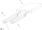
- the figure 1 shows a two-part conveyor 12 with two conveyor units 1 that are not physically connected to one another DE 10 2007 046 868 A1 and the DE 10 2019 001 125 A1 known.
- the figure 1 also shows how the CUs in lowered state can drive under a load carrier 11 (transport pallet/"Euro pallet") in order to subsequently raise the load carrier for transport.
- a load carrier 11 transport pallet/"Euro pallet
- the figure 2 shows schematically one of these conveyor units 1 in a lowered state, in which a load carrier 11 can be driven under.
- a pair of rollers 3 is arranged in the front and rear area of the conveyor unit 1, with only one roller 3 being visible in each case.
- the contact surfaces of the front and rear rollers define a floor plane 6, in relation to which the lowered conveyor unit 1 has a constant distance b 2 over its entire extent.
- the installation spaces provided for the sensor units 7 , the drive units 8 , the energy store 9 and the control device 10 are therefore also at a distance b 2 from the floor plane 6 .
- the support element 4 designed as an enveloping structure, which not only has a vertical wall surrounding all parts or components of the conveyor unit 1, but also a horizontal upper side, with which it contacts load carriers 11 to be lifted. From the figure 2 It is easy to see that due to the low ground clearance over the entire extent of the conveyor unit 1, a maximum amount of installation space can be used without exceeding a maximum installation height predetermined by the clearance gauge of load carriers. In the lowered state of the conveyor unit 1 , however, driving over or driving through uneven ground would not be possible without risking contact with the ground and consequently also a loss of function/traction of the conveyor unit 1 or even damage to the conveyor unit 1 .
- the figure 4 shows the conveyor unit 1 in the raised state and when driving over a convexly curved unevenness in the floor, which is between the pairs of rollers 3 above the floor level 6 (see Figures 2 and 3 ) extends out and, thanks to the increased ground clearance, does not contact the frame 2 of the conveyor unit 1.
- the figure 5 shows in an analogous manner how the present invention makes it possible to drive through a concave unevenness in the ground without ground contact occurring in the front or rear area of the conveyor unit 1 .
Landscapes
- Engineering & Computer Science (AREA)
- Transportation (AREA)
- Structural Engineering (AREA)
- Civil Engineering (AREA)
- Life Sciences & Earth Sciences (AREA)
- Geology (AREA)
- Mechanical Engineering (AREA)
- Rollers For Roller Conveyors For Transfer (AREA)
Applications Claiming Priority (1)
| Application Number | Priority Date | Filing Date | Title |
|---|---|---|---|
| DE102021128247.0A DE102021128247A1 (de) | 2021-10-29 | 2021-10-29 | Ladungsträger-Fördereinheit mit erhöhter Bodenfreiheit |
Publications (3)
| Publication Number | Publication Date |
|---|---|
| EP4174015A1 true EP4174015A1 (fr) | 2023-05-03 |
| EP4174015C0 EP4174015C0 (fr) | 2025-06-18 |
| EP4174015B1 EP4174015B1 (fr) | 2025-06-18 |
Family
ID=84043906
Family Applications (1)
| Application Number | Title | Priority Date | Filing Date |
|---|---|---|---|
| EP22203936.4A Active EP4174015B1 (fr) | 2021-10-29 | 2022-10-26 | Unité de transport de porteurs de charge avec garde au sol améliorée |
Country Status (4)
| Country | Link |
|---|---|
| EP (1) | EP4174015B1 (fr) |
| DE (1) | DE102021128247A1 (fr) |
| ES (1) | ES3040190T3 (fr) |
| PL (1) | PL4174015T3 (fr) |
Families Citing this family (2)
| Publication number | Priority date | Publication date | Assignee | Title |
|---|---|---|---|---|
| DE102022213914B4 (de) * | 2022-12-19 | 2025-07-17 | Zf Friedrichshafen Ag | Einweisungssystem für ein geführtes Unterfahren einer Wechselbrücke |
| DE102023207177A1 (de) * | 2023-07-27 | 2025-01-30 | Kamag Transporttechnik Gmbh & Co. Kg | Verfahren zur Vermeidung von Erkennungen einer Fahrbahn durch eine Personenschutzeinrichtung sowie fahrerloses Transportfahrzeug |
Citations (6)
| Publication number | Priority date | Publication date | Assignee | Title |
|---|---|---|---|---|
| DE102007046868A1 (de) | 2007-09-28 | 2009-04-16 | Universität Stuttgart | Transportvorrichtung für Ladungsträger und Verfahren zu deren Steuerung |
| EP2336075A1 (fr) | 2009-12-15 | 2011-06-22 | AMX Automation Technologies GmbH | Dispositif de transport sans conducteur |
| EP3521236A1 (fr) * | 2018-01-31 | 2019-08-07 | Toyota Material Handling Manufacturing Sweden AB | Véhicule de manutention de matériaux |
| WO2020164942A1 (fr) * | 2019-02-15 | 2020-08-20 | FILICS GmbH | Dispositif de transport pour porte-charge |
| DE102019001125A1 (de) | 2019-02-15 | 2020-08-20 | FILICS GmbH | Fördereinrichtung für Ladungsträger mit integrierter Kollisionsdetektion |
| US20210197900A1 (en) * | 2019-12-27 | 2021-07-01 | Grey Orange Pte. Ltd. | Transport vehicle for transporting payloads |
Family Cites Families (3)
| Publication number | Priority date | Publication date | Assignee | Title |
|---|---|---|---|---|
| NO2966067T3 (fr) | 2013-08-12 | 2018-03-24 | ||
| DE102013017062A1 (de) | 2013-10-15 | 2015-04-16 | Eisenmann Ag | Fördereinheit und Fördersystem zum Fördern von Ladungsträgern |
| DE202016106329U1 (de) | 2016-11-11 | 2016-12-15 | Mk-Lietz Maschinen & Apparatebau | Transportwagen |
-
2021
- 2021-10-29 DE DE102021128247.0A patent/DE102021128247A1/de active Pending
-
2022
- 2022-10-26 EP EP22203936.4A patent/EP4174015B1/fr active Active
- 2022-10-26 PL PL22203936.4T patent/PL4174015T3/pl unknown
- 2022-10-26 ES ES22203936T patent/ES3040190T3/es active Active
Patent Citations (6)
| Publication number | Priority date | Publication date | Assignee | Title |
|---|---|---|---|---|
| DE102007046868A1 (de) | 2007-09-28 | 2009-04-16 | Universität Stuttgart | Transportvorrichtung für Ladungsträger und Verfahren zu deren Steuerung |
| EP2336075A1 (fr) | 2009-12-15 | 2011-06-22 | AMX Automation Technologies GmbH | Dispositif de transport sans conducteur |
| EP3521236A1 (fr) * | 2018-01-31 | 2019-08-07 | Toyota Material Handling Manufacturing Sweden AB | Véhicule de manutention de matériaux |
| WO2020164942A1 (fr) * | 2019-02-15 | 2020-08-20 | FILICS GmbH | Dispositif de transport pour porte-charge |
| DE102019001125A1 (de) | 2019-02-15 | 2020-08-20 | FILICS GmbH | Fördereinrichtung für Ladungsträger mit integrierter Kollisionsdetektion |
| US20210197900A1 (en) * | 2019-12-27 | 2021-07-01 | Grey Orange Pte. Ltd. | Transport vehicle for transporting payloads |
Also Published As
| Publication number | Publication date |
|---|---|
| PL4174015T3 (pl) | 2025-10-13 |
| ES3040190T3 (en) | 2025-10-29 |
| DE102021128247A1 (de) | 2023-05-04 |
| EP4174015C0 (fr) | 2025-06-18 |
| EP4174015B1 (fr) | 2025-06-18 |
Similar Documents
| Publication | Publication Date | Title |
|---|---|---|
| DE4012692C2 (de) | Fahrzeugtransportsystem für ein mehrstöckiges Parkhaus | |
| AT519139B1 (de) | Regalbediengerät und Regallagersystem mit verbesserter Zugänglichkeit und Gewichtsverteilung | |
| EP0780326B1 (fr) | Transporteur à accumulation avec au moins un moyen de transport sans fin | |
| EP1140670A2 (fr) | Procede et systeme d'entreposage destines au transfert de charges | |
| EP4174015B1 (fr) | Unité de transport de porteurs de charge avec garde au sol améliorée | |
| EP1446353A1 (fr) | Dispositif servant a deplacer un moyen de suspension de charge en sens transversal dans un systeme en hauteur destine a manipuler des unites de stockage | |
| EP4373766A1 (fr) | Système transtockeur, entrepôt à rayonnages en hauteur, procédé de mise en stock et de sortie du stock | |
| WO2013044895A1 (fr) | Dispositif de déplacement d'unités de transport | |
| DE60011738T2 (de) | Wagen zum Befördern von Fahrzeugen in einem Parkhaus | |
| EP4301678A1 (fr) | Système de stockage et de récupération | |
| EP2200911A1 (fr) | Étagère d'entreposage à gestion du chargement | |
| EP0327724B1 (fr) | Transélévateur et rayonnages hauts correspondants | |
| EP0668225A1 (fr) | Installation de chargement pour véhicules utilitaires ou rampes | |
| DE10020909A1 (de) | Vorrichtung zur Förderung einer Vorratsrolle | |
| EP0180710A2 (fr) | Dispositif de transport des colis de détail ou des marchandises semblables | |
| EP4206097A1 (fr) | Station de centrage et procede de manutention d' au moins un support de charge | |
| DE69305248T2 (de) | Automatisiertes Gerät zum Beladen und Entladen von Motorfahrzeugen | |
| DE2510347A1 (de) | Vorrichtung zur ueberfuehrung einer last von einer foerdereinrichtung auf eine andere foerdereinrichtung | |
| EP0137471B1 (fr) | Convoyeur d'accumulation à chaîne pour des colis suspendus | |
| AT402728B (de) | Vakuum-eingabegerät | |
| DE3921123A1 (de) | Trolleyfahrzeug zum ein- und auslagern von speicherguttragenden ladungstraegern | |
| DE29815729U1 (de) | Ladevorrichtung zum Be- und Entladen eines Fahrzeugs | |
| CH627974A5 (en) | Lorry with a lifting device | |
| DE102024118933B3 (de) | Modulares Mobilliftsystem | |
| EP3640196B1 (fr) | Chariot de manutention autonome fixé au sol et procédé de chargement et de déchargement d'une unité de chargement à l'aide d'un tel chariot de manutention |
Legal Events
| Date | Code | Title | Description |
|---|---|---|---|
| PUAI | Public reference made under article 153(3) epc to a published international application that has entered the european phase |
Free format text: ORIGINAL CODE: 0009012 |
|
| STAA | Information on the status of an ep patent application or granted ep patent |
Free format text: STATUS: THE APPLICATION HAS BEEN PUBLISHED |
|
| AK | Designated contracting states |
Kind code of ref document: A1 Designated state(s): AL AT BE BG CH CY CZ DE DK EE ES FI FR GB GR HR HU IE IS IT LI LT LU LV MC ME MK MT NL NO PL PT RO RS SE SI SK SM TR |
|
| STAA | Information on the status of an ep patent application or granted ep patent |
Free format text: STATUS: REQUEST FOR EXAMINATION WAS MADE |
|
| 17P | Request for examination filed |
Effective date: 20231102 |
|
| RBV | Designated contracting states (corrected) |
Designated state(s): AL AT BE BG CH CY CZ DE DK EE ES FI FR GB GR HR HU IE IS IT LI LT LU LV MC ME MK MT NL NO PL PT RO RS SE SI SK SM TR |
|
| RAP3 | Party data changed (applicant data changed or rights of an application transferred) |
Owner name: FILICS GMBH |
|
| GRAP | Despatch of communication of intention to grant a patent |
Free format text: ORIGINAL CODE: EPIDOSNIGR1 |
|
| STAA | Information on the status of an ep patent application or granted ep patent |
Free format text: STATUS: GRANT OF PATENT IS INTENDED |
|
| INTG | Intention to grant announced |
Effective date: 20250117 |
|
| GRAS | Grant fee paid |
Free format text: ORIGINAL CODE: EPIDOSNIGR3 |
|
| GRAA | (expected) grant |
Free format text: ORIGINAL CODE: 0009210 |
|
| STAA | Information on the status of an ep patent application or granted ep patent |
Free format text: STATUS: THE PATENT HAS BEEN GRANTED |
|
| AK | Designated contracting states |
Kind code of ref document: B1 Designated state(s): AL AT BE BG CH CY CZ DE DK EE ES FI FR GB GR HR HU IE IS IT LI LT LU LV MC ME MK MT NL NO PL PT RO RS SE SI SK SM TR |
|
| REG | Reference to a national code |
Ref country code: GB Ref legal event code: FG4D Free format text: NOT ENGLISH |
|
| REG | Reference to a national code |
Ref country code: CH Ref legal event code: EP |
|
| REG | Reference to a national code |
Ref country code: DE Ref legal event code: R096 Ref document number: 502022004312 Country of ref document: DE |
|
| REG | Reference to a national code |
Ref country code: CH Ref legal event code: EP |
|
| REG | Reference to a national code |
Ref country code: IE Ref legal event code: FG4D Free format text: LANGUAGE OF EP DOCUMENT: GERMAN |
|
| U01 | Request for unitary effect filed |
Effective date: 20250715 |
|
| U07 | Unitary effect registered |
Designated state(s): AT BE BG DE DK EE FI FR IT LT LU LV MT NL PT RO SE SI Effective date: 20250721 |
|
| PG25 | Lapsed in a contracting state [announced via postgrant information from national office to epo] |
Ref country code: GR Free format text: LAPSE BECAUSE OF FAILURE TO SUBMIT A TRANSLATION OF THE DESCRIPTION OR TO PAY THE FEE WITHIN THE PRESCRIBED TIME-LIMIT Effective date: 20250919 Ref country code: NO Free format text: LAPSE BECAUSE OF FAILURE TO SUBMIT A TRANSLATION OF THE DESCRIPTION OR TO PAY THE FEE WITHIN THE PRESCRIBED TIME-LIMIT Effective date: 20250918 |
|
| PG25 | Lapsed in a contracting state [announced via postgrant information from national office to epo] |
Ref country code: HR Free format text: LAPSE BECAUSE OF FAILURE TO SUBMIT A TRANSLATION OF THE DESCRIPTION OR TO PAY THE FEE WITHIN THE PRESCRIBED TIME-LIMIT Effective date: 20250618 |
|
| PG25 | Lapsed in a contracting state [announced via postgrant information from national office to epo] |
Ref country code: RS Free format text: LAPSE BECAUSE OF FAILURE TO SUBMIT A TRANSLATION OF THE DESCRIPTION OR TO PAY THE FEE WITHIN THE PRESCRIBED TIME-LIMIT Effective date: 20250918 |
|
| REG | Reference to a national code |
Ref country code: ES Ref legal event code: FG2A Ref document number: 3040190 Country of ref document: ES Kind code of ref document: T3 Effective date: 20251029 |
|
| U20 | Renewal fee for the european patent with unitary effect paid |
Year of fee payment: 4 Effective date: 20251028 |
|
| PG25 | Lapsed in a contracting state [announced via postgrant information from national office to epo] |
Ref country code: IS Free format text: LAPSE BECAUSE OF FAILURE TO SUBMIT A TRANSLATION OF THE DESCRIPTION OR TO PAY THE FEE WITHIN THE PRESCRIBED TIME-LIMIT Effective date: 20251018 |
|
| PG25 | Lapsed in a contracting state [announced via postgrant information from national office to epo] |
Ref country code: SM Free format text: LAPSE BECAUSE OF FAILURE TO SUBMIT A TRANSLATION OF THE DESCRIPTION OR TO PAY THE FEE WITHIN THE PRESCRIBED TIME-LIMIT Effective date: 20250618 |
|
| PG25 | Lapsed in a contracting state [announced via postgrant information from national office to epo] |
Ref country code: CZ Free format text: LAPSE BECAUSE OF FAILURE TO SUBMIT A TRANSLATION OF THE DESCRIPTION OR TO PAY THE FEE WITHIN THE PRESCRIBED TIME-LIMIT Effective date: 20250618 |
|
| PGFP | Annual fee paid to national office [announced via postgrant information from national office to epo] |
Ref country code: PL Payment date: 20251016 Year of fee payment: 4 |
|
| PG25 | Lapsed in a contracting state [announced via postgrant information from national office to epo] |
Ref country code: SK Free format text: LAPSE BECAUSE OF FAILURE TO SUBMIT A TRANSLATION OF THE DESCRIPTION OR TO PAY THE FEE WITHIN THE PRESCRIBED TIME-LIMIT Effective date: 20250618 |
|
| PGFP | Annual fee paid to national office [announced via postgrant information from national office to epo] |
Ref country code: ES Payment date: 20251216 Year of fee payment: 4 |
|
| REG | Reference to a national code |
Ref country code: CH Ref legal event code: W10 Free format text: ST27 STATUS EVENT CODE: U-0-0-W10-W00 (AS PROVIDED BY THE NATIONAL OFFICE) Effective date: 20260402 |
|
| PLBE | No opposition filed within time limit |
Free format text: ORIGINAL CODE: 0009261 |
|
| STAA | Information on the status of an ep patent application or granted ep patent |
Free format text: STATUS: NO OPPOSITION FILED WITHIN TIME LIMIT |
|
| RAP4 | Party data changed (patent owner data changed or rights of a patent transferred) |
Owner name: FILICS GMBH |
|
| U1H | Name or address of the proprietor changed after the registration of the unitary effect |
Owner name: FILICS GMBH; DE |
|
| REG | Reference to a national code |
Ref country code: CH Ref legal event code: L10 Free format text: ST27 STATUS EVENT CODE: U-0-0-L10-L00 (AS PROVIDED BY THE NATIONAL OFFICE) Effective date: 20260430 |