EP4209617A1 - Structure composite métal-résine à base d'aluminium, élément métallique à base d'aluminium, procédé de fabrication - Google Patents
Structure composite métal-résine à base d'aluminium, élément métallique à base d'aluminium, procédé de fabrication Download PDFInfo
- Publication number
- EP4209617A1 EP4209617A1 EP23157515.0A EP23157515A EP4209617A1 EP 4209617 A1 EP4209617 A1 EP 4209617A1 EP 23157515 A EP23157515 A EP 23157515A EP 4209617 A1 EP4209617 A1 EP 4209617A1
- Authority
- EP
- European Patent Office
- Prior art keywords
- aluminum
- based metal
- metal member
- resin
- less
- Prior art date
- Legal status (The legal status is an assumption and is not a legal conclusion. Google has not performed a legal analysis and makes no representation as to the accuracy of the status listed.)
- Withdrawn
Links
Images


Classifications
-
- C—CHEMISTRY; METALLURGY
- C23—COATING METALLIC MATERIAL; COATING MATERIAL WITH METALLIC MATERIAL; CHEMICAL SURFACE TREATMENT; DIFFUSION TREATMENT OF METALLIC MATERIAL; COATING BY VACUUM EVAPORATION, BY SPUTTERING, BY ION IMPLANTATION OR BY CHEMICAL VAPOUR DEPOSITION, IN GENERAL; INHIBITING CORROSION OF METALLIC MATERIAL OR INCRUSTATION IN GENERAL
- C23F—NON-MECHANICAL REMOVAL OF METALLIC MATERIAL FROM SURFACE; INHIBITING CORROSION OF METALLIC MATERIAL OR INCRUSTATION IN GENERAL; MULTI-STEP PROCESSES FOR SURFACE TREATMENT OF METALLIC MATERIAL INVOLVING AT LEAST ONE PROCESS PROVIDED FOR IN CLASS C23 AND AT LEAST ONE PROCESS COVERED BY SUBCLASS C21D OR C22F OR CLASS C25
- C23F1/00—Etching metallic material by chemical means
- C23F1/10—Etching compositions
- C23F1/14—Aqueous compositions
- C23F1/16—Acidic compositions
- C23F1/20—Acidic compositions for etching aluminium or alloys thereof
-
- B—PERFORMING OPERATIONS; TRANSPORTING
- B29—WORKING OF PLASTICS; WORKING OF SUBSTANCES IN A PLASTIC STATE IN GENERAL
- B29C—SHAPING OR JOINING OF PLASTICS; SHAPING OF MATERIAL IN A PLASTIC STATE, NOT OTHERWISE PROVIDED FOR; AFTER-TREATMENT OF THE SHAPED PRODUCTS, e.g. REPAIRING
- B29C65/00—Joining or sealing of preformed parts, e.g. welding of plastics materials; Apparatus therefor
- B29C65/70—Joining or sealing of preformed parts, e.g. welding of plastics materials; Apparatus therefor by moulding
-
- B—PERFORMING OPERATIONS; TRANSPORTING
- B29—WORKING OF PLASTICS; WORKING OF SUBSTANCES IN A PLASTIC STATE IN GENERAL
- B29C—SHAPING OR JOINING OF PLASTICS; SHAPING OF MATERIAL IN A PLASTIC STATE, NOT OTHERWISE PROVIDED FOR; AFTER-TREATMENT OF THE SHAPED PRODUCTS, e.g. REPAIRING
- B29C45/00—Injection moulding, i.e. forcing the required volume of moulding material through a nozzle into a closed mould; Apparatus therefor
- B29C45/14—Injection moulding, i.e. forcing the required volume of moulding material through a nozzle into a closed mould; Apparatus therefor incorporating preformed parts or layers, e.g. injection moulding around inserts or for coating articles
-
- B—PERFORMING OPERATIONS; TRANSPORTING
- B29—WORKING OF PLASTICS; WORKING OF SUBSTANCES IN A PLASTIC STATE IN GENERAL
- B29C—SHAPING OR JOINING OF PLASTICS; SHAPING OF MATERIAL IN A PLASTIC STATE, NOT OTHERWISE PROVIDED FOR; AFTER-TREATMENT OF THE SHAPED PRODUCTS, e.g. REPAIRING
- B29C45/00—Injection moulding, i.e. forcing the required volume of moulding material through a nozzle into a closed mould; Apparatus therefor
- B29C45/0001—Injection moulding, i.e. forcing the required volume of moulding material through a nozzle into a closed mould; Apparatus therefor characterised by the choice of material
-
- B—PERFORMING OPERATIONS; TRANSPORTING
- B29—WORKING OF PLASTICS; WORKING OF SUBSTANCES IN A PLASTIC STATE IN GENERAL
- B29C—SHAPING OR JOINING OF PLASTICS; SHAPING OF MATERIAL IN A PLASTIC STATE, NOT OTHERWISE PROVIDED FOR; AFTER-TREATMENT OF THE SHAPED PRODUCTS, e.g. REPAIRING
- B29C45/00—Injection moulding, i.e. forcing the required volume of moulding material through a nozzle into a closed mould; Apparatus therefor
- B29C45/0053—Injection moulding, i.e. forcing the required volume of moulding material through a nozzle into a closed mould; Apparatus therefor combined with a final operation, e.g. shaping
- B29C45/006—Joining parts moulded in separate cavities
- B29C45/0062—Joined by injection moulding
-
- B—PERFORMING OPERATIONS; TRANSPORTING
- B29—WORKING OF PLASTICS; WORKING OF SUBSTANCES IN A PLASTIC STATE IN GENERAL
- B29C—SHAPING OR JOINING OF PLASTICS; SHAPING OF MATERIAL IN A PLASTIC STATE, NOT OTHERWISE PROVIDED FOR; AFTER-TREATMENT OF THE SHAPED PRODUCTS, e.g. REPAIRING
- B29C45/00—Injection moulding, i.e. forcing the required volume of moulding material through a nozzle into a closed mould; Apparatus therefor
- B29C45/14—Injection moulding, i.e. forcing the required volume of moulding material through a nozzle into a closed mould; Apparatus therefor incorporating preformed parts or layers, e.g. injection moulding around inserts or for coating articles
- B29C45/14311—Injection moulding, i.e. forcing the required volume of moulding material through a nozzle into a closed mould; Apparatus therefor incorporating preformed parts or layers, e.g. injection moulding around inserts or for coating articles using means for bonding the coating to the articles
-
- B—PERFORMING OPERATIONS; TRANSPORTING
- B29—WORKING OF PLASTICS; WORKING OF SUBSTANCES IN A PLASTIC STATE IN GENERAL
- B29C—SHAPING OR JOINING OF PLASTICS; SHAPING OF MATERIAL IN A PLASTIC STATE, NOT OTHERWISE PROVIDED FOR; AFTER-TREATMENT OF THE SHAPED PRODUCTS, e.g. REPAIRING
- B29C45/00—Injection moulding, i.e. forcing the required volume of moulding material through a nozzle into a closed mould; Apparatus therefor
- B29C45/14—Injection moulding, i.e. forcing the required volume of moulding material through a nozzle into a closed mould; Apparatus therefor incorporating preformed parts or layers, e.g. injection moulding around inserts or for coating articles
- B29C45/14336—Coating a portion of the article, e.g. the edge of the article
-
- B—PERFORMING OPERATIONS; TRANSPORTING
- B29—WORKING OF PLASTICS; WORKING OF SUBSTANCES IN A PLASTIC STATE IN GENERAL
- B29C—SHAPING OR JOINING OF PLASTICS; SHAPING OF MATERIAL IN A PLASTIC STATE, NOT OTHERWISE PROVIDED FOR; AFTER-TREATMENT OF THE SHAPED PRODUCTS, e.g. REPAIRING
- B29C66/00—General aspects of processes or apparatus for joining preformed parts
- B29C66/70—General aspects of processes or apparatus for joining preformed parts characterised by the composition, physical properties or the structure of the material of the parts to be joined; Joining with non-plastics material
- B29C66/74—Joining plastics material to non-plastics material
- B29C66/742—Joining plastics material to non-plastics material to metals or their alloys
- B29C66/7422—Aluminium or alloys of aluminium
-
- C—CHEMISTRY; METALLURGY
- C23—COATING METALLIC MATERIAL; COATING MATERIAL WITH METALLIC MATERIAL; CHEMICAL SURFACE TREATMENT; DIFFUSION TREATMENT OF METALLIC MATERIAL; COATING BY VACUUM EVAPORATION, BY SPUTTERING, BY ION IMPLANTATION OR BY CHEMICAL VAPOUR DEPOSITION, IN GENERAL; INHIBITING CORROSION OF METALLIC MATERIAL OR INCRUSTATION IN GENERAL
- C23C—COATING METALLIC MATERIAL; COATING MATERIAL WITH METALLIC MATERIAL; SURFACE TREATMENT OF METALLIC MATERIAL BY DIFFUSION INTO THE SURFACE, BY CHEMICAL CONVERSION OR SUBSTITUTION; COATING BY VACUUM EVAPORATION, BY SPUTTERING, BY ION IMPLANTATION OR BY CHEMICAL VAPOUR DEPOSITION, IN GENERAL
- C23C22/00—Chemical surface treatment of metallic material by reaction of the surface with a reactive liquid, leaving reaction products of surface material in the coating, e.g. conversion coatings, passivation of metals
- C23C22/05—Chemical surface treatment of metallic material by reaction of the surface with a reactive liquid, leaving reaction products of surface material in the coating, e.g. conversion coatings, passivation of metals using aqueous solutions
- C23C22/06—Chemical surface treatment of metallic material by reaction of the surface with a reactive liquid, leaving reaction products of surface material in the coating, e.g. conversion coatings, passivation of metals using aqueous solutions using aqueous acidic solutions with pH less than 6
- C23C22/48—Chemical surface treatment of metallic material by reaction of the surface with a reactive liquid, leaving reaction products of surface material in the coating, e.g. conversion coatings, passivation of metals using aqueous solutions using aqueous acidic solutions with pH less than 6 not containing phosphates, hexavalent chromium compounds, fluorides or complex fluorides, molybdates, tungstates, vanadates or oxalates
- C23C22/56—Treatment of aluminium or alloys based thereon
-
- C—CHEMISTRY; METALLURGY
- C23—COATING METALLIC MATERIAL; COATING MATERIAL WITH METALLIC MATERIAL; CHEMICAL SURFACE TREATMENT; DIFFUSION TREATMENT OF METALLIC MATERIAL; COATING BY VACUUM EVAPORATION, BY SPUTTERING, BY ION IMPLANTATION OR BY CHEMICAL VAPOUR DEPOSITION, IN GENERAL; INHIBITING CORROSION OF METALLIC MATERIAL OR INCRUSTATION IN GENERAL
- C23C—COATING METALLIC MATERIAL; COATING MATERIAL WITH METALLIC MATERIAL; SURFACE TREATMENT OF METALLIC MATERIAL BY DIFFUSION INTO THE SURFACE, BY CHEMICAL CONVERSION OR SUBSTITUTION; COATING BY VACUUM EVAPORATION, BY SPUTTERING, BY ION IMPLANTATION OR BY CHEMICAL VAPOUR DEPOSITION, IN GENERAL
- C23C22/00—Chemical surface treatment of metallic material by reaction of the surface with a reactive liquid, leaving reaction products of surface material in the coating, e.g. conversion coatings, passivation of metals
- C23C22/05—Chemical surface treatment of metallic material by reaction of the surface with a reactive liquid, leaving reaction products of surface material in the coating, e.g. conversion coatings, passivation of metals using aqueous solutions
- C23C22/68—Chemical surface treatment of metallic material by reaction of the surface with a reactive liquid, leaving reaction products of surface material in the coating, e.g. conversion coatings, passivation of metals using aqueous solutions using aqueous solutions with pH between 6 and 8
-
- C—CHEMISTRY; METALLURGY
- C23—COATING METALLIC MATERIAL; COATING MATERIAL WITH METALLIC MATERIAL; CHEMICAL SURFACE TREATMENT; DIFFUSION TREATMENT OF METALLIC MATERIAL; COATING BY VACUUM EVAPORATION, BY SPUTTERING, BY ION IMPLANTATION OR BY CHEMICAL VAPOUR DEPOSITION, IN GENERAL; INHIBITING CORROSION OF METALLIC MATERIAL OR INCRUSTATION IN GENERAL
- C23C—COATING METALLIC MATERIAL; COATING MATERIAL WITH METALLIC MATERIAL; SURFACE TREATMENT OF METALLIC MATERIAL BY DIFFUSION INTO THE SURFACE, BY CHEMICAL CONVERSION OR SUBSTITUTION; COATING BY VACUUM EVAPORATION, BY SPUTTERING, BY ION IMPLANTATION OR BY CHEMICAL VAPOUR DEPOSITION, IN GENERAL
- C23C22/00—Chemical surface treatment of metallic material by reaction of the surface with a reactive liquid, leaving reaction products of surface material in the coating, e.g. conversion coatings, passivation of metals
- C23C22/73—Chemical surface treatment of metallic material by reaction of the surface with a reactive liquid, leaving reaction products of surface material in the coating, e.g. conversion coatings, passivation of metals characterised by the process
-
- C—CHEMISTRY; METALLURGY
- C23—COATING METALLIC MATERIAL; COATING MATERIAL WITH METALLIC MATERIAL; CHEMICAL SURFACE TREATMENT; DIFFUSION TREATMENT OF METALLIC MATERIAL; COATING BY VACUUM EVAPORATION, BY SPUTTERING, BY ION IMPLANTATION OR BY CHEMICAL VAPOUR DEPOSITION, IN GENERAL; INHIBITING CORROSION OF METALLIC MATERIAL OR INCRUSTATION IN GENERAL
- C23F—NON-MECHANICAL REMOVAL OF METALLIC MATERIAL FROM SURFACE; INHIBITING CORROSION OF METALLIC MATERIAL OR INCRUSTATION IN GENERAL; MULTI-STEP PROCESSES FOR SURFACE TREATMENT OF METALLIC MATERIAL INVOLVING AT LEAST ONE PROCESS PROVIDED FOR IN CLASS C23 AND AT LEAST ONE PROCESS COVERED BY SUBCLASS C21D OR C22F OR CLASS C25
- C23F1/00—Etching metallic material by chemical means
- C23F1/10—Etching compositions
- C23F1/14—Aqueous compositions
- C23F1/32—Alkaline compositions
- C23F1/36—Alkaline compositions for etching aluminium or alloys thereof
-
- B—PERFORMING OPERATIONS; TRANSPORTING
- B29—WORKING OF PLASTICS; WORKING OF SUBSTANCES IN A PLASTIC STATE IN GENERAL
- B29C—SHAPING OR JOINING OF PLASTICS; SHAPING OF MATERIAL IN A PLASTIC STATE, NOT OTHERWISE PROVIDED FOR; AFTER-TREATMENT OF THE SHAPED PRODUCTS, e.g. REPAIRING
- B29C45/00—Injection moulding, i.e. forcing the required volume of moulding material through a nozzle into a closed mould; Apparatus therefor
- B29C45/14—Injection moulding, i.e. forcing the required volume of moulding material through a nozzle into a closed mould; Apparatus therefor incorporating preformed parts or layers, e.g. injection moulding around inserts or for coating articles
- B29C45/14008—Inserting articles into the mould
-
- B—PERFORMING OPERATIONS; TRANSPORTING
- B29—WORKING OF PLASTICS; WORKING OF SUBSTANCES IN A PLASTIC STATE IN GENERAL
- B29K—INDEXING SCHEME ASSOCIATED WITH SUBCLASSES B29B, B29C OR B29D, RELATING TO MOULDING MATERIALS OR TO MATERIALS FOR MOULDS, REINFORCEMENTS, FILLERS OR PREFORMED PARTS, e.g. INSERTS
- B29K2023/00—Use of polyalkenes or derivatives thereof as moulding material
- B29K2023/10—Polymers of propylene
- B29K2023/12—PP, i.e. polypropylene
-
- B—PERFORMING OPERATIONS; TRANSPORTING
- B29—WORKING OF PLASTICS; WORKING OF SUBSTANCES IN A PLASTIC STATE IN GENERAL
- B29K—INDEXING SCHEME ASSOCIATED WITH SUBCLASSES B29B, B29C OR B29D, RELATING TO MOULDING MATERIALS OR TO MATERIALS FOR MOULDS, REINFORCEMENTS, FILLERS OR PREFORMED PARTS, e.g. INSERTS
- B29K2067/00—Use of polyesters or derivatives thereof, as moulding material
-
- B—PERFORMING OPERATIONS; TRANSPORTING
- B29—WORKING OF PLASTICS; WORKING OF SUBSTANCES IN A PLASTIC STATE IN GENERAL
- B29K—INDEXING SCHEME ASSOCIATED WITH SUBCLASSES B29B, B29C OR B29D, RELATING TO MOULDING MATERIALS OR TO MATERIALS FOR MOULDS, REINFORCEMENTS, FILLERS OR PREFORMED PARTS, e.g. INSERTS
- B29K2075/00—Use of PU, i.e. polyureas or polyurethanes or derivatives thereof, as moulding material
-
- B—PERFORMING OPERATIONS; TRANSPORTING
- B29—WORKING OF PLASTICS; WORKING OF SUBSTANCES IN A PLASTIC STATE IN GENERAL
- B29K—INDEXING SCHEME ASSOCIATED WITH SUBCLASSES B29B, B29C OR B29D, RELATING TO MOULDING MATERIALS OR TO MATERIALS FOR MOULDS, REINFORCEMENTS, FILLERS OR PREFORMED PARTS, e.g. INSERTS
- B29K2101/00—Use of unspecified macromolecular compounds as moulding material
- B29K2101/12—Thermoplastic materials
-
- B—PERFORMING OPERATIONS; TRANSPORTING
- B29—WORKING OF PLASTICS; WORKING OF SUBSTANCES IN A PLASTIC STATE IN GENERAL
- B29K—INDEXING SCHEME ASSOCIATED WITH SUBCLASSES B29B, B29C OR B29D, RELATING TO MOULDING MATERIALS OR TO MATERIALS FOR MOULDS, REINFORCEMENTS, FILLERS OR PREFORMED PARTS, e.g. INSERTS
- B29K2703/00—Use of resin-bonded materials for preformed parts, e.g. inserts
- B29K2703/04—Inorganic materials
- B29K2703/06—Metal powders, metal carbides or the like
-
- B—PERFORMING OPERATIONS; TRANSPORTING
- B29—WORKING OF PLASTICS; WORKING OF SUBSTANCES IN A PLASTIC STATE IN GENERAL
- B29K—INDEXING SCHEME ASSOCIATED WITH SUBCLASSES B29B, B29C OR B29D, RELATING TO MOULDING MATERIALS OR TO MATERIALS FOR MOULDS, REINFORCEMENTS, FILLERS OR PREFORMED PARTS, e.g. INSERTS
- B29K2705/00—Use of metals, their alloys or their compounds, for preformed parts, e.g. for inserts
- B29K2705/02—Aluminium
Definitions
- the present invention relates to an aluminum-based metal-resin composite structure, an aluminum-based metal member, a method for manufacturing an aluminum-based metal member, and a method for manufacturing an aluminum-based metal-resin composite structure.
- Patent Document 1 proposes a technique to integrate aluminum and resin by carrying out an immersion treatment on an aluminum alloy in warm water to form a microporous hydroxyl group-containing dendritic layer with a thickness of 5 to 100 nm on the surface thereof, then injection molding a thermoplastic resin, mainly polybutylene phthalate or polyphenylene sulfide, on the treated surface.
- a thermoplastic resin mainly polybutylene phthalate or polyphenylene sulfide
- Patent Document 2 discloses a composite body formed of a metal component, in which a surface is covered with pore openings with a number average inner diameter of 10 to 80 nm formed by an anodic oxidation method, and a resin composition component of a resin composition including 70 to 99% by weight of polyphenylene sulfide and 1 to 30% by weight of polyolefin-based resin and which is adhered to the metal component described above by injection molding.
- the present inventors confirmed that, when faithfully following the invention contents described in Patent Document 1 and verifying the effects thereof, even in cases where the same aluminum alloy test pieces are resin-bonded under the same surface treatment conditions and the same forming conditions, there are cases where the aluminum alloy-resin bonding exhibits high bonding strength at the level of base metal failure, on the other hand, there are cases where the bonding strength does not develop at all due to interface failure. That is, the mechanical properties of the composite bodies manufactured by the method described in the document have an inherent problem in that the reproducibility of the effect of the invention is poor. Furthermore, it was confirmed that the bonding strength of the composite body obtained by resin injection into roughened metal left indoors decreases with the time left indoors and that this tendency is remarkably apparent at high temperatures and high humidity. In other words, in order to keep the usable time (pot life) of the roughened metal obtained by the method described in the above document constant, special environmental controls and innovations are necessary.
- the present invention is created in consideration of the above circumstances and provides an aluminum-based metal-resin composite structure which is able to directly bond an aluminum-based metal member and a resin member formed of a thermoplastic resin composition without using an adhesive and which has excellent bonding strength between the aluminum-based metal member and the resin member.
- the present invention provides an aluminum-based metal member able to stably obtain an aluminum-based metal-resin composite structure having excellent bonding strength between an aluminum-based metal member and a resin member, a method for manufacturing the same, and a method for manufacturing an aluminum-based metal-resin composite structure.
- the present inventors carried out intensive research to minimize variations in the bonding strength between an aluminum-based metal and a resin in aluminum-based metal-resin composite structures and to develop a stable bonding strength. As a result, it was found that the treated aluminum-based metal surface satisfying specific microstructure requirements significantly improves the stability of the bonding strength, thereby completing the present invention.
- an aluminum-based metal-resin composite structure an aluminum-based metal member, a method for manufacturing an aluminum-based metal member, and a method for manufacturing an aluminum-based metal-resin composite structure are provided, as illustrated below.
- an aluminum-based metal-resin composite structure which is able to directly bond an aluminum-based metal member and a resin member formed of a thermoplastic resin composition without using an adhesive and in which the bonding strength between the aluminum-based metal member and the resin member is excellent.
- an aluminum-based metal member which is able to stably obtain an aluminum-based metal-resin composite structure in which the bonding strength between the aluminum-based metal member and a resin member is excellent, a method for manufacturing the same, and a method for manufacturing an aluminum-based metal-resin composite structure.
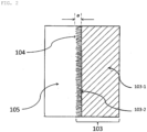
- the aluminum-based metal-resin composite structure 106 is provided with an aluminum-based metal member 103, in which a dendritic layer 103-2 is formed on at least a part of the surface thereof, and a resin member 105, which is bonded to the aluminum-based metal member 103 via the dendritic layer 103-2 and formed of a thermoplastic resin composition (P) .
- the dendritic layer 103-2 refers to a layer in which a plurality of branched trunks stand together.
- trunks that stand together from the surface of the aluminum-based metal member 103 are referred to as "main trunks”
- branches that split off from the main trunks are referred to as “main branches”
- branches that split off from the main branches are referred to as "side branches”.
- Fig. 1 is an external view showing an example of the structure of the aluminum-based metal-resin composite structure 106 of an embodiment according to the present invention.
- Fig. 2 is a cross-sectional view conceptually showing an example of a bonding portion of the aluminum-based metal-resin composite structure 106 of an embodiment according to the present invention.
- the aluminum-based metal member 103 forming the aluminum-based metal-resin composite structure 106 is substantially identical to the aluminum-based metal member 103 before the resin member 105 is bonded in all points, including the surface microstructure (morphology). That is, as described in the Examples below, in the aluminum-based metal member 103 according to the present embodiment, the surface microstructure of the aluminum-based metal member 103 does not change significantly before and after the injection bonding of the resin member 105. Therefore, in the present embodiment, unless otherwise specified, the aluminum-based metal member 103 encompasses not only the aluminum-based metal member before the resin member 105 is bonded, but also the aluminum-based metal member forming the aluminum-based metal-resin composite structure 106, to which the resin member 105 is bonded.
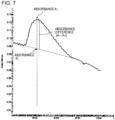
- an absorbance of an absorption peak observed at 3400 cm -1 is defined as A 1 and an absorbance at 3400 cm -1 of a straight line connecting an absorbance at 3800 cm -1 and an absorbance at 2500 cm -1 is defined as A 0
- an absorbance difference (A 1 - A 0 ) is in a range of 0.03 or less.
- the lower limit of the absorbance difference (A 1 - A 0 ) is preferably 0.005 or more, and more preferably 0.01 or more and the upper limit of the absorbance difference (A 1 - A 0 ) is preferably 0.02 or less.
- Fig. 7 shows an example of a method for determining the absorbance difference (A 1 - A 0 ) from an FTIR chart.
- a high-sensitivity reflection method (RAS method) is employed and the angle of incidence of infrared light is 85°.
- the broad absorption peak with a peak top at 3400 cm -1 observed in FTIR measurement is presumed to be a peak caused by aluminum hydroxide or aluminum hydrate oxide.
- the absorbance difference (A 1 - A 0 ) is an indicator showing the degree of hydroxyl group retention on the metal surface.
- the relationship between the amount of hydroxyl groups on the metal surface and the bonding strength is still unclear in many respects, but the present inventors consider the following. That is, in a case where there are more hydroxyl groups on the metal surface, it is easier to adsorb moisture in the environment and form a water molecular layer on the surface, which is particularly remarkable in a high humidity environment. As a result, it is considered that the bonding strength between the metal and resin decreases.
- the average number density of the main trunks of the dendritic layer 103-2 according to the present embodiment is 5 trunks/ ⁇ m or more and 40 trunks/ ⁇ m or less, preferably 7 trunks/um or more, and more preferably 10 trunks/um or more, and preferably 35 trunks/ ⁇ m or less, and more preferably 30 trunks/ ⁇ m or less.
- the average number density of main trunks of the dendritic layer 103-2 for example, by selecting a certain area from an SEM photograph of the surface of the aluminum-based metal member 103, counting the "number of main trunks" which grow from the surface of the aluminum-based metal member 103, and carrying out a conversion per each unit length of the base, as shown in Fig. 8 .
- the aluminum-based metal-resin composite structure 106 of the present embodiment it is sufficient to satisfy one of the above configuration for the absorbance difference (A 1 - A 0 ) and the above configuration for the average number density of the main trunks, but it is preferable to satisfy both above configurations for the absorbance difference (A 1 - A 0 ) and the above configuration for the average number density of the main trunks.
- the aluminum-based metal-resin composite structure 106 of the present embodiment has excellent bonding strength between the aluminum-based metal member 103 and the resin member 105 since the dendritic layer 103-2 is interposed on a bonding portion surface 104.
- the dendritic layer 103-2 is formed on a micron-ordered micro-convex structure, sufficient bonding strength is developed even if the amount of metal etching is reduced when the micro-convex shape is formed by, for example, chemical etching.
- the average thickness of the dendritic layer 103-2 is, for example, 20 nm or more and less than 1000 nm, preferably 30 nm or more and 900 nm or less, more preferably 50 nm or more and 800 nm or less, and even more preferably 100 nm or more and 700 nm or less.
- the average thickness in the present embodiment is determined by taking SEM photographs of any 10 points on the metal member, then measuring the average thickness at a length of 1 um for any two spots for each photograph, making similar measurements for the other nine spots, and obtaining the average value of the measurement values for a total of 20 points.
- the aluminum-based metal-resin composite structure 106 maintains a high bonding strength and the deterioration of surface properties is suppressed even after long-term storage. That is, it is possible to further extend the usable time (pot life) .
- the usable time pot life
- these excellent properties for example, in a case where the metal-resin composite structure is prepared by insert molding of the resin member on the roughened metal member by the method described below, a certain amount of the roughened metal member is prepared in a batch and used sequentially within the usable time, which frees the process from the work of having to prepare the roughened metal member immediately before each molding.
- the shape of the aluminum-based metal base surface on which the dendritic layer 103-2 is formed may be flat, curved, or uneven, or the flat shape of the aluminum-basedmetal product itself, without being particularly limited.
- the surface on which the dendritic layer 103-2 is formed in the aluminum-based metal member 103 according to the present embodiment preferably satisfies either of the following properties (1) and (2) for a total of six linear portions formed of any three linear portions in a parallel relationship and any three linear portions orthogonal to the first three linear portions and more preferably satisfies the following requirements (1) and (2) at the same time.
- the dendritic layer 103-2 of the present embodiment is preferably formed on a micron-order rough surface which satisfies the following requirements (1) and (2) at the same time.
- Such a rough surface is referred to below as a double rough surface and may be distinguished from a rough surface where the dendritic layer 103-2 is formed on a commercial aluminum-based metal surface itself (single rough surface) .
- the micron-order rough surface which is the base may be referred to as the base rough surface and the dendritic layer coated on the base rough surface may be referred to as the fine rough surface.
- the bonding strength of the aluminum-based metal-resin composite body obtained therefrom may be increased in comparison with the bonding strength of an aluminum-based metal-resin composite body obtained from a single rough surface.
- the amount of metal etching during the preparation of the base rough surface is reduced in the aluminum-based metal-resin composite body obtained from the double rough surface, since it is possible to suppress the tendency of the bonding strength to decrease, this leads to a reduction in the amount of metal loss and is more economical.
- the use of a double rough surface makes it possible to significantly lower the mold temperature compared to a case of using a single rough surface. As a result, it is possible to suppress the amount of warpage and deformation which is generated during the process in which the composite body taken out after the mold is opened goes from the mold temperature to the ambient temperature.
- Fig. 6 is a schematic diagram for illustrating a total of six linear portions on the bonding portion surface 104 of the metal member 103, which are formed of any three linear portions in a parallel relationship and any three linear portions orthogonal to the first three linear portions.
- a center line B1 passing through the center A of the bonding portion surface 104 of the metal member 103 is selected as a reference line.
- straight lines B2 and B3 in a parallel relationship with the center line B1 are selected.
- a center line B4, which is orthogonal to the center line B1 is selected and straight lines B5 and B6, which are orthogonal to the center line B1 and have a parallel relationship with the center line B4, are selected.
- vertical distances D1 to D4 between each straight line are, for example, 2 to 5 mm.
- a surface roughening treatment is carried out with respect to an entire surface 110 of the metal member 103, not only to the bonding portion surface 104 in the surface 110 of the metal member 103.
- six linear portions from locations other than the bonding portion surface 104 may be selected from the same metal member 103 surface as the bonding portion surface 104.
- the aluminum-based metal-resin composite structure 106 according to the present embodiment is obtained by the thermoplastic resin composition (P) forming the resin member 105 penetrating the dendritic layer formed on the surface 110 of the aluminum-based metal member 103 to bond the aluminum-based metal and the resin and form an aluminum-based metal-resin interface.
- a dendritic layer suitable for improving the bonding strength between the aluminum-based metal member 103 and the resin member 105 is formed on the surface of the aluminum-based metal member 103, it is possible to secure the bonding property between the aluminum-based metal member 103 and the resin member 105 without using an adhesive. That is, it is considered that, due to the penetration of the thermoplastic resin composition (P) into the dendritic layer on the surface 110 of the aluminum-based metal member 103, a physical resistance force (anchor effect) between the aluminum-based metal member 103 and the resin member 105 is effectively expressed and it is possible to firmly bond the aluminum-based metal member 103 and the resin member 105 formed of the thermoplastic resin composition (P), which are normally difficult to bond.
- the aluminum-based metal-resin composite structure 106 obtained in this manner to prevent water and moisture from entering the interface between the aluminum-based metal member 103 and the resin member 105.
- the aluminum-based metal member 103 preferably has a specific surface area according to the BET three-point method with nitrogen adsorption of 0.01 m 2 /g or more and 1.0 m 2 /g or less, and more preferably 0.05 m 2 /g or more and 0.5 m 2 /g or less.
- the above specific surface area is within the range described above, the amount of penetration of the resin member 105 into the aluminum-based metal member 103 increases, thus, it is possible to further improve the bonding strength between the resin member 105 and the aluminum-based metal member 103.
- the aluminum-based metal member 103 of the present embodiment is obtained by roughening a commercially available aluminum-based metal base material by the method described below to impart a rough surface thereto.
- commercially available aluminum-based metal base materials include an aluminum base material formed of aluminum alone, an aluminum alloy base material formed of an aluminum alloy, and the like.
- the 1000 series which is industrial pure aluminum (aluminum alone)
- the 2000 series alloy which is Al-Cu
- the 3000 series alloy which is Al-Mn
- the 4000 series alloy which is Al-Si
- the 5000 series alloy which is Al-Mg
- the 6000 series alloy which is Al-Mg-Si
- the 7000 series alloy which is Al-Zn-Mg.
- alloy numbers 1050, 1100, 2014, 2024, 3003, 5052, 6063, 7075, and the like it is preferable to use alloy numbers 1050, 1100, 2014, 2024, 3003, 5052, 6063, 7075, and the like.
- the shape of the aluminum-based metal base material which is the raw material of the aluminum-based metal member 103, is not particularly limited as long as bonding with the resin member 105 is possible, and, for example, a flat plate, a curved plate, a rod, a cylinder, a lump, and the like are possible.
- the shape may also be a structure formed of a combination of the above.
- the shape of the metal base material surface forming the bonding portion surface 104 to be bonded with the resin member 105 is not limited and examples thereof include a flat surface, a curved surface, and the like.
- the aluminum-based metal member 103 is preferably processed into the predetermined shape described above by carrying out plastic working such as cutting or pressing, or removal processing such as punching, shaving, polishing, or electrical discharge machining on the aluminum-based metal base material and then subjected to a roughening treatment as described below. In short, it is preferable to use a product processed into the required shape by various processing methods.
- the resin member 105 is formed of the thermoplastic resin composition (P).
- the thermoplastic resin composition (P) includes a thermoplastic resin (A) as a resin component and a filler (B) as necessary. Further, the thermoplastic resin composition (P) includes other blending agents as necessary. For convenience, even in a case where the resin member 105 is formed of only the thermoplastic resin (A), the resin member 105 is described as formed of the thermoplastic resin composition (P).
- the thermoplastic resin (A) is not particularly limited, but includes, for example, a polyolefin-based resin, a polymethacrylic-based resin such as polymethyl methacrylate resin, a polyacrylic-based resin such as methyl polyacrylate resin, a polystyrene resin, a polyvinyl alcohol-polyvinyl chloride copolymer resin, a polyvinyl acetal resin, a polyvinyl butyral resin, a polyvinyl formyl resin, a polymethylpentene resin, a maleic anhydride-styrene copolymer resin, a polycarbonate resin, a polyphenylene ether resin, aromatic polyetherketones such as a polyether ether ketone resin and a polyether ketone resin, polyester-based resins, polyamide-based resins, polyamide-imide resins, polyimide resins, polyetherimide resins, styrene-based elastomers, polyole
- thermoplastic resin (A) from the viewpoint that it is possible to more stably obtain a high bonding strength between the aluminum-based metal member 103 and the resin member 105, one type or two or more types of thermoplastic resins selected from a polyolefin-based resin, a polyester-based resin, a polyamide-based resin, and a polyarylene-based resin are suitably used.
- thermoplastic resin composition (P) may further include the filler (B) from the viewpoint of adjusting the linear expansion coefficient difference between the aluminum-based metal member 103 and the resin member 105 and improving the mechanical strength of the resin member 105.
- the filler (B) for example, it is possible to select one type or two or more types from the group formed of glass fibers, carbon fibers, carbon particles, clay, talc, silica, minerals, and cellulose fibers. Among these, one type or two or more types are preferably selected from glass fibers, carbon fibers, talc, and minerals.
- the shape of the filler (B) is not particularly limited and may be any shape, such as fibrous, particulate, or plate-like.
- the filler (B) preferably has a number fraction of 5 to 100% of a filler with a maximum length in the range of 10 nm or more and 600 um or less.
- the maximum length is more preferably 30 nm or more and 550 um or less and even more preferably 50 nm or more and 500 ⁇ m or less.
- the number fraction of the filler (B) in the range of this maximum length is preferably 10 to 100%, and more preferably 20 to 100%.
- the filler (B) When the maximum length of the filler (B) is in the above range, it is possible for the filler (B) to easily move in the molten thermoplastic resin (A) during the molding of the thermoplastic resin composition (P), thus, it is possible for the filler (B) to be present near the surface of the aluminum-based metal member 103 at a certain ratio during the manufacturing of the aluminum-based metal-resin composite structure 106 described below. Therefore, as described above, the resin which interacts with the filler (B) enters the uneven shape of the surface of the aluminum-based metal member 103, making it possible to have a stronger bonding strength. In addition, when the number fraction of the filler (B) is in the above range, a number fraction of the fillers (B) sufficient to interact with the uneven shape of the surface of the aluminum-based metal member 103 is present in the thermoplastic resin composition (P).
- thermoplastic resin composition (P) includes the filler (B)
- the content thereof is preferably 1 part by mass or more and 100 part by mass or less with respect to 100 part by mass of the thermoplastic resin (A), more preferably from 5 parts by mass or more and 90 parts by mass or less, and particularly preferably 10 parts by mass or more and 80 parts by mass or less.
- the thermoplastic resin composition (P) may include other blending agents for the purpose of imparting individual functions.
- Such blending agents include heat stabilizers, antioxidants, pigments, weathering agents, flame retardants, plasticizers, dispersants, lubricants, mold release agents, antistatic agents, and the like.
- the content of the blending agents is preferably 0.0001 to 5 parts by mass with respect to 100 parts by mass of the thermoplastic resin (A), and more preferably 0.001 to 3 parts by mass.
- thermoplastic resin composition (P) is not particularly limited and preparation by generally known methods is possible. Examples thereof include the following method. First, the thermoplastic resin composition (P) is obtained by mixing or melt-mixing the above thermoplastic resin (A), the above filler (B) as necessary, and also the other blending agents as necessary, using a mixing device such as a Banbury mixer, a single-screw extruder, a twin-screw extruder, or a high-speed twin-screw extruder.
- a mixing device such as a Banbury mixer, a single-screw extruder, a twin-screw extruder, or a high-speed twin-screw extruder.
- the aluminum-based metal member 103 according to the present embodiment is classified as double rough surface or single rough surface, as described above. It is possible to form a double rough surface by imparting a base rough surface having a micron-order micro-convex structure to the surface 110 of the metal member 103 using a known method such as a chemical etching agent, an anodic oxidation method, or a mechanical cutting method, and then imparting a fine rough surface on the base rough surface. It is possible to form a single rough surface by immediately imparting a fine rough surface on a commercially available aluminum-based metal base material without imparting a base rough surface. Below, the formation method will be described in detail using a double rough surface as an example.
- a base rough surface having a micron-order micro-convex structure by any known metal surface roughening method. Examples thereof include chemical treatment methods; anodic oxidation methods; and mechanical cutting methods such as sandblasting, knurling, and laser processing. It is possible to use these known methods alone or in combination as appropriate.
- treatment with an acid-based etching agent is preferable.
- a known treatment method using an acid-based etching agent for example, it is possible to employ the treatment methods disclosed in International Publication No. 2015/8847 , Japanese Unexamined Patent Application Publication No. 2001-348684 , International Publication No. 2008/81933 , and the like.
- a particularly preferable method of forming a base rough surface having a fine uneven structure on the surface 110 of the metal member 103 is to carry out the following steps (1) to (4) in this order.
- This step is for removing a film formed of an oxide film, a hydroxide, or the like present on the surface of the metal member 103 on the bonding side with the resin member 105.
- a mechanical polishing or chemical polishing treatment is performed.
- a treatment with an alkaline solution such as a sodium hydroxide solution or a potassium hydroxide solution, or degreasing may be performed.
- This step is for forming a zinc-containing film on the surface of a metal member by immersing the metal member 103 after pretreatment in a zinc ion-containing alkaline aqueous solution including alkali hydroxide (MOH) and zinc ions (Zn 2+ ) in a weight ratio (MOH/Zn 2+ ) of 1 to 100.
- M in MOH is an alkali metal or alkaline earth metal.
- this step is formed of washing with water and drying operations.
- An ultrasonic cleaning operation may be included to remove smut.
- the metal member obtained by the above method which has been imparted with a base rough surface having a micron-order micro-convex structure, is then brought into contact with an oxidizing acidic aqueous solution including metal cations with a standard electrode potential E° at 25°C of greater than -0.2 and 0.8 or less, preferably greater than 0 and 0.5 or less, to chemically roughen the surface of the metal member to impart a fine rough surface thereto.
- the above oxidizing acidic aqueous solution preferably does not include the metal cations with an E 0 of -0.2 or less described above.
- metal cations for which the standard electrode potential E° at 25°C is greater than -0.2 and 0.8 or less Pb 2+ , Sn 2+ , Ag + , Hg 2+ , Cu 2+ , and the like.
- Cu 2+ is preferable from the viewpoints of scarcity of the metal and the safety and toxicity of the corresponding metal salt.
- inorganic compounds such as copper hydroxide, cupric oxide, cupric chloride, cupric bromide, copper sulfate, and copper nitrate and it is possible to use these compounds in the present invention without limitation; however, copper oxide is preferably used from the viewpoints of safety and toxicity of the inorganic compounds and the efficiency of imparting a dendritic layer.
- nitric acid or an acid which is a mixture of nitric acid with any of hydrochloric acid, hydrofluoric acid, or sulfuric acid As an oxidizing acidic aqueous solution, it is possible to illustrate nitric acid or an acid which is a mixture of nitric acid with any of hydrochloric acid, hydrofluoric acid, or sulfuric acid. Furthermore, a percarboxylic acid solution represented by peracetic acid or performic acid may be used.
- the concentration of nitric acid forming the aqueous solution is, for example, 10% by mass to 40% by mass, preferably 15% by mass to 38% by mass, and more preferably 20% by mass to 35% by mass.
- the concentration of copper ions (secondary copper ions) forming the aqueous solution is, for example, 1% by mass to 15% by mass, preferably 2% by mass to 12% by mass, and more preferably 2% by mass to 8% by mass.
- concentration of nitric acid is less than 10% by mass, the copper ions may not be fully dissolved, which is not preferable, while in a case where the concentration exceeds 40% by mass, the viscosity of the aqueous solution itself increases, such that it may not be possible to impart a sufficient roughening effect with respect to the metal surface, which is also not preferable in terms of safety.
- the concentration is less than 1% by mass, the roughening efficiency of the metal is not sufficient and the bonding strength may be reduced in the case of a composite body, while when the concentration is greater than 15% by mass, the cupric oxide is not sufficiently dissolved and there is a possibility red copper residue may be left on the metal surface, which is not preferable.
- a treatment temperature of, for example, room temperature to 60°C, and preferably 30°C to 50°C, is employed in order to complete the roughening at an economical speed while controlling the exothermic reaction.
- the treatment time at this time is in the range of, for example, 1 minute to 15 minutes, and preferably 2 minutes to 10 minutes.
- the aluminum-based metal member formed in this manner and having a fine rough surface on the base rough surface is washed with water and subjected to a drying treatment as necessary to provide the aluminum-based metal member 103 for resin bonding.
- the aluminum-based metal-resin composite structure 106 of the present embodiment for example, by inserting the aluminum-based metal member 103 obtained by the above method into a cavity portion of an injection mold and then molding the resin member 105 by an injection molding method in which the thermoplastic resin composition (P) is injected into the injection mold.
- This manufacturing method specifically includes steps [1] to [3] below.
- thermoplastic resin composition (P) The step of preparing the thermoplastic resin composition (P) is as described above. A description will be given below of the injection molding method according to steps [2] and [3].
- a mold for injection molding is prepared, the mold is opened, and the aluminum-based metal member 103 is placed in a part of the mold.
- thermoplastic resin composition (P) obtained in step [1] is injected into the above mold, such that at least a part of the thermoplastic resin composition (P) is brought into contact with the formation region of the dendritic layer 103-2 on the surface 110 of the aluminum-based metal member 103 and solidified. Thereafter, it is possible to obtain the aluminum-based metal-resin composite structure 106 by opening and releasing the mold.
- injection foam molding and rapid heat cycle molding in which the mold is heated and cooled rapidly, may be used.
- RHCM heating and cooling molding
- a method of injection foam molding there are methods of adding a chemical foaming agent to the resin, methods of injecting nitrogen gas or carbon dioxide gas directly into a cylinder portion of an injection molding machine, and a MuCell injection foam molding method in which nitrogen gas or carbon dioxide gas is injected into a cylinder portion of an injection molding machine in a supercritical state, but it is possible to obtain the aluminum-based metal-resin composite structure 106 in which the resin member 105 is a foamed body with any of these methods.
- a method of controlling the mold it is also possible to use counter pressure, or to use core-back molding depending on the shape of the molded product.
- rapid heat cycle molding it is possible to implement rapid heat cycle molding by connecting a rapid heating and cooling device to the mold. It is possible for the rapid heating and cooling device to be any commonly used method.
- a heating method it is possible to use any one method of a steam method, a pressurized hot water method, a hot water method, a thermal oil method, an electric heater method, an electromagnetic induction superheating method, or a combination thereof.
- a cooling method it is possible to use any one method of a cold-water method, a cold-oil method, or a combination thereof.
- thermoplastic resin composition (P) As the conditions of the high-speed heat cycle molding method, for example, it is desirable to heat the injection mold to a temperature of 100°C or higher and 250°C or lower and cool the injection mold after the injection of the thermoplastic resin composition (P) is completed.
- the preferable temperature range for heating the mold varies depending on the thermoplastic resin (A) which forms the thermoplastic resin composition (P), for a crystalline resin which is a thermoplastic resin with a melting point of lower than 200°C, 100°C or higher and 150°C or lower is preferable, and for a crystalline resin which is a thermoplastic resin with a melting point of 200°C or higher, 140°C or higher and 250°C or lower is desirable.
- amorphous resins 100°C or higher and 180°C or lower is desirable.
- the aluminum-based metal-resin composite structure 106 has high productivity and a high degree of freedom in shape control and is thus able to be developed for various applications.
- the aluminum-based metal-resin composite structure 106 according to the present embodiment exhibits high air tightness and liquid tightness and is thus suitable for applications in accordance with these properties.
- Examples thereof include structural components for vehicles, vehicle-mounted articles, housings for electronic equipment, housings for household appliances, structural components, mechanical components, components for various automobiles, components for electronic equipment, applications for household goods such as furniture and kitchenware, medical equipment, components for building materials, other structural components and exterior components, and the like.
- More specific examples include the following components, which are designed such that the aluminum-based metal supports the portions which are not strong enough as resin alone.
- Examples relating to vehicles include instrument panels, console boxes, door knobs, door trims, shift levers, pedal types, glove boxes, bumpers, hoods, fenders, trunks, doors, roofs, pillars, seat sheets, radiators, oil pans, steering wheels, ECU boxes, electrical components, and the like.
- examples of building materials and furniture include glass window frames, railings, curtain rails, chests, drawers, closets, bookcases, desks, chairs, and the like.
- examples of precision electronic components include connectors, relays, gears, and the like.
- examples of transport containers include shipping containers, suitcases, trunks, and the like.
- the high thermal conductivity of the aluminum-based metal member 103 and the adiabatic properties of the resin member 105 for use in component applications used in equipment optimally designed for heat management, for example, various home appliances and various cooling devices.
- various home appliances and various cooling devices include home appliances such as refrigerators, washing machines, vacuum cleaners, microwave ovens, air conditioners, lighting equipment, electric water heaters, televisions, clocks, ventilating fans, projectors, and speakers, electronic information equipment such as personal computers, cell phones, smart phones, digital cameras, tablet PCs, portable music players, portable game machines, chargers, and batteries, cooling units for heating elements such as CPUs and lithium-ion secondary batteries, and the like.
- Examples of other applications include toys, sports equipment, shoes, sandals, bags, tableware such as forks, knives, spoons, and plates, stationery such as ballpoint pens, mechanical pencils, files, and binders, cooking utensils such as frying pans, pots, kettles, spatulas, ladles, hole ladles, whiskers, and tongs, components for lithium-ion secondary batteries, robots, and the like.
- An aluminum alloy sheet (thickness: 2.0 mm) of alloy number A5052 specified in JIS H4000 was cut to a length of 45 mm and a width of 18 mm.
- the aluminum alloy sheet was subjected to a degreasing treatment and then immersed for 2 minutes in a treatment tank 1 filled with an alkaline etching agent (30°C) containing 19.0% by mass of sodium hydroxide and 3.2% by mass of zinc oxide (in the following description, this may be abbreviated as a "zinc pretreatment”), and then washed with water.
- an alkaline etching agent (30°C) containing 19.0% by mass of sodium hydroxide and 3.2% by mass of zinc oxide
- the obtained aluminum alloy sheet was immersed for 6 minutes at 30°C in a treatment tank 2 filled with an acid-based etching solution containing 3.9% by mass of ferric chloride, 0.2% by mass of cupric chloride, and 4.1% by mass of sulfuric acid, and subjected to oscillation (in the following description, this may be abbreviated as "Treatment 1"). Then, ultrasonic cleaning (one minute in water) was performed under running water.
- the aluminum alloy sheet treated in this manner was immersed for 5 minutes at 40°C in a treatment tank 3 filled with an acid-based etching solution containing 6.3% by mass (5.0% by mass as Cu 2+ ) of cupric oxide and 30.0% by mass of nitric acid and subjected to oscillation (in the following description, this may be abbreviated as "Treatment 2").
- the aluminum alloy sheet was washed with running water and dried at 80°C for 15 minutes to obtain an aluminum alloy sheet.
- the standard electrode potential E 0 of Cu 2+ used in Treatment 2 is +0.337 (V vs. SHE).
- the surface roughness of the obtained surface-treated aluminum alloy sheet was measured using a surface roughness measuring device "Surfcom 1400D (manufactured by Tokyo Seimitsu Co., Ltd.)" and, from the surface roughness measured in accordance with JIS B0601 (corresponding to ISO 4287), the ten-point average roughness (Rz jis ) and the average length of the roughness curve elements (RS m ) were measured, respectively.
- the average value of R zjis was 14 um and the average value of RS m was 135 um.
- the R zjis average value and RS m average value are the averages of the measurement values at six points at different measuring locations. As shown in Fig. 6 , the measurement locations were set at a total of six linear areas, formed of any three linear portions on the bonding portion surface 104 of the metal member 103 and any three linear portions orthogonal to the first linear portions.
- the surface roughness measurement conditions are as follows.
- the specific surface area of the obtained surface-treated aluminum alloy sheets was measured by the following method. As a result, the specific surface area was 0.21 m 2 /g.
- the adsorption isotherm was measured by the nitrogen gas adsorption method under liquid nitrogen temperature (77K) using BELSORP-max (manufactured by MicrotracBELL Corp.), and the specific surface area was determined by the BET method.
- the cross-sectional structure of the above surface-treated aluminum alloy sheets was observed by SEM and, as a result, dendritic layers with an average thickness of 490 nm were observed.
- the FT-IR spectrum of the surface of the above surface-treated aluminum alloy sheet was measured using a device combining a Fourier Transform Infrared Spectrophotometer (FTIR) manufactured by Shimadzu Corporation and a high-sensitivity reflectance measurement device (RAS-8000) at an angle of incidence of 85° to infrared light.
- FTIR Fourier Transform Infrared Spectrophotometer
- RAS-8000 high-sensitivity reflectance measurement device
- Fig. 8 shows the SEM profile of the surface of the obtained surface-treated aluminum alloy sheet. According to this, the average number density of main trunks of the dendritic layer was calculated to be 28 trunks/um.
- the average number density of the main trunks of the dendritic layer was measured at a total of 10 locations in one measurement sample and the average value thereof was adopted.
- the storage stability of the above surface-treated aluminum alloy sheets was investigated by the following method. First, three sets of five surface-treated aluminum alloy sheets were prepared, which were double-sealed in a zippered plastic bag (product name: Unipak) so as to not overlap each other. The three sets of sealed sheets were then stored in a constant temperature and humidity tank at 40°C and 90% RH. The aluminum alloy sheets before setting (day 0) and five aluminum alloy sheets from the aluminum alloy sheet sealed sheets after storage for 14, 28, and 56 days were taken out and five specimens of aluminum-based metal-resin composite structures were manufactured by the injection molding step described below. Next, the shear strengths of the five specimens of aluminum-based metal-resin composite structures were measured by the method described below and the average value thereof was used as the bonding strength. As a result, the bonding strength of the samples after 56 days of storage was found to be within a 5% decrease rate from the bonding strength of the samples before setting.
- the aluminum alloy sheet immediately after surface treatment obtained by the above method was immediately placed in a small dumbbell metal insert mold mounted on a J55-AD injection molding machine manufactured by Japan Steel Works, Ltd.
- glass fiber reinforced polypropylene [V7100 manufactured by Prime Polymer Co., Ltd.; formed of 80% by mass of polypropylene (MFR (230°C, 2.16 kg load) : 18 g/10 min) and 20% by mass of glass fiber] as the resin composition (P) was injection molded into the mold under conditions of a cylinder temperature of 230°C, a mold temperature of 80°C, a primary injection pressure of 93 MPa, a holding pressure of 80 MPa, and an injection speed of 25 mm/sec to obtain an aluminum-based metal-resin composite structure.
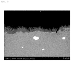
- Fig. 3 shows an example of a SEM photograph of the cross-section of the bonding portion of the obtained aluminum-based metal-resin composite structure.
- the average thickness of the dendritic layer was calculated to be 500 nm. It was confirmed that the nano-order dendritic layer formed a cover so as to follow the micron-order uneven shape. This dendritic layer was also observed in the same manner in the SEM analysis of the surface of the aluminum alloy sheet before injection molding as described above (refer to Fig. 8 ) and the average thickness thereof was 490 nm.
- the average thickness of the dendritic layer was determined from cross-sectional SEM photographs of the aluminum-based metal member before injection molding.
- a tensile shear strength measurement test of the bonding portion was carried out on the aluminum-based metal-resin composite structure obtained from the above injection molding step. Specifically, using a tensile testing machine "Model 1323 (manufactured by Aikoh Engineering Co., Ltd.)", a dedicated jig was attached to the tensile testing machine and the bonding strength measurement was performed under conditions of an inter-chuck distance of 60 mm and a tensile speed of 10 mm/min at room temperature (23°C) .
- the bonding strength (MPa) was obtained by dividing the breaking load (N) by the area of the bonding portion between the aluminum alloy sheet and the resin member. The bonding strength was 23. 6 (MPa) .
- Example 1 The same operation as in Example 1 was performed except that an aluminum alloy sheet of alloy number A2024 was used instead of an aluminum alloy sheet of alloy number A5052 specified in JIS H4000. The results are summarized in Table 1.
- Example 1 The same operation as in Example 1 was performed except that an aluminum alloy sheet of alloy number A6063 was used instead of an aluminum alloy sheet of alloy number A5052 specified in JIS H4000. The results are summarized in Table 1.
- Example 1 The same operations as in Example 1 were carried out except that, as the resin composition (P) used in the injection molding step, instead of glass fiber reinforced polypropylene (V7100 manufactured by Prime Polymer Co., Ltd.), glass fiber reinforced polyamide 6 (GM1011G30 manufactured by Toray Industries, Inc.; glass fiber content 30% by mass, abbreviated in the Table as PA6) was used and the mold temperature during the injection molding step was set to 90°C.
- the resin composition (P) used in the injection molding step instead of glass fiber reinforced polypropylene (V7100 manufactured by Prime Polymer Co., Ltd.
- glass fiber reinforced polyamide 6 GM1011G30 manufactured by Toray Industries, Inc.; glass fiber content 30% by mass, abbreviated in the Table as PA6
- Example 1 The same operation as in Example 1 was performed except that the mold temperature during the injection molding step was lowered to 70°C. The results are summarized in Table 1.
- Example 1 The same operation as in Example 1 was performed except that the mold temperature during the injection molding step was increased to 120°C. The results are summarized in Table 1.
- Example 6 The same operation as in Example 6 was performed except that Treatment 2 was not performed. The results are summarized in Table 1.
- Example 4 The same operation as in Example 4 was performed except that Treatment 2 was not performed. The results are summarized in Table 1.
- An aluminum alloy sheet (thickness: 2.0 mm) of alloy number A5052 specified in JIS H4000 was cut to a length of 45 mm and a width of 18 mm.
- the same treatment 1 as in Example 1 was performed on this aluminum alloy sheet, then immersed in a 30% by mass nitric acid solution for 5 minutes at 65°C, and then washed thoroughly with water. After that, the result was immersed in a hot water tank at 70°C for 10 minutes and subjected to oscillation (in the following description, this may be abbreviated as "Treatment 3"), then ultrasonic cleaning (one minute in water) was performed under running water, and then drying was carried out to obtain a surface-treated aluminum alloy sheet. The amount of etching was measured and the result was 8.0% by mass.
- the surface roughness was measured by the same method as described in Example 1 using a surface roughness measuring device "Surfcom 1400D (manufactured by Tokyo Seimitsu Co., Ltd.)" and, as a result, the average value of R zjis was 13 um and the average value of RS m was 137 ⁇ m.
- the nano-order dendritic layer a cover so as to follow the micron-order uneven shape.
- the average thickness of the dendritic layer was estimated to be 210 nm.
- An aluminum-based metal-resin composite structure was obtained by performing injection molding with respect to the surface-treated aluminum alloy sheet obtained by the above method in exactly the same manner as in Example 1, excluding the point that the mold temperature was 120°C.
- the bonding strength of the composite body was 22.0 MPa (base metal failure).
- Example 1 The same operation as in Example 1 was performed except that Treatment 1 was not performed and a surface-treated aluminum alloy sheet formed of a single rough surface was obtained. The results are summarized in Table 1. Injection molding was performed with respect to this surface-treated aluminum alloy sheet in exactly the same manner as in Example 1 and an aluminum-based metal-resin composite structure was obtained. The results are summarized in Table 1.
Landscapes
- Chemical & Material Sciences (AREA)
- Engineering & Computer Science (AREA)
- Mechanical Engineering (AREA)
- Manufacturing & Machinery (AREA)
- Chemical Kinetics & Catalysis (AREA)
- General Chemical & Material Sciences (AREA)
- Materials Engineering (AREA)
- Metallurgy (AREA)
- Organic Chemistry (AREA)
- Laminated Bodies (AREA)
- Injection Moulding Of Plastics Or The Like (AREA)
- ing And Chemical Polishing (AREA)
Applications Claiming Priority (3)
| Application Number | Priority Date | Filing Date | Title |
|---|---|---|---|
| JP2019013396 | 2019-01-29 | ||
| EP20748421.3A EP3919653A4 (fr) | 2019-01-29 | 2020-01-29 | Structure composite métal-résine à base d'aluminium, élément métallique à base d'aluminium, procédé de fabrication d'un élément métallique à base d'aluminium, et procédé de fabrication de structure composite métal-résine à base d'aluminium |
| PCT/JP2020/003252 WO2020158820A1 (fr) | 2019-01-29 | 2020-01-29 | Structure composite métal-résine à base d'aluminium, élément métallique à base d'aluminium, procédé de fabrication d'un élément métallique à base d'aluminium, et procédé de fabrication de structure composite métal-résine à base d'aluminium |
Related Parent Applications (1)
| Application Number | Title | Priority Date | Filing Date |
|---|---|---|---|
| EP20748421.3A Division EP3919653A4 (fr) | 2019-01-29 | 2020-01-29 | Structure composite métal-résine à base d'aluminium, élément métallique à base d'aluminium, procédé de fabrication d'un élément métallique à base d'aluminium, et procédé de fabrication de structure composite métal-résine à base d'aluminium |
Publications (1)
| Publication Number | Publication Date |
|---|---|
| EP4209617A1 true EP4209617A1 (fr) | 2023-07-12 |
Family
ID=71841540
Family Applications (2)
| Application Number | Title | Priority Date | Filing Date |
|---|---|---|---|
| EP23157515.0A Withdrawn EP4209617A1 (fr) | 2019-01-29 | 2020-01-29 | Structure composite métal-résine à base d'aluminium, élément métallique à base d'aluminium, procédé de fabrication |
| EP20748421.3A Pending EP3919653A4 (fr) | 2019-01-29 | 2020-01-29 | Structure composite métal-résine à base d'aluminium, élément métallique à base d'aluminium, procédé de fabrication d'un élément métallique à base d'aluminium, et procédé de fabrication de structure composite métal-résine à base d'aluminium |
Family Applications After (1)
| Application Number | Title | Priority Date | Filing Date |
|---|---|---|---|
| EP20748421.3A Pending EP3919653A4 (fr) | 2019-01-29 | 2020-01-29 | Structure composite métal-résine à base d'aluminium, élément métallique à base d'aluminium, procédé de fabrication d'un élément métallique à base d'aluminium, et procédé de fabrication de structure composite métal-résine à base d'aluminium |
Country Status (7)
| Country | Link |
|---|---|
| US (1) | US20220097311A1 (fr) |
| EP (2) | EP4209617A1 (fr) |
| JP (3) | JP7225269B2 (fr) |
| KR (2) | KR102746414B1 (fr) |
| CN (1) | CN113396243B (fr) |
| MX (1) | MX2021009077A (fr) |
| WO (1) | WO2020158820A1 (fr) |
Cited By (1)
| Publication number | Priority date | Publication date | Assignee | Title |
|---|---|---|---|---|
| EP4186994A4 (fr) * | 2020-07-22 | 2024-12-18 | Mitsui Chemicals, Inc. | Élément métallique, composite métal-résine et procédé de production d'un élément métallique |
Families Citing this family (3)
| Publication number | Priority date | Publication date | Assignee | Title |
|---|---|---|---|---|
| EP4381945A4 (fr) | 2021-08-05 | 2025-08-27 | Mitsui Chemicals Inc | Matériau métallique antibactérien et article antibactérien |
| JP7807529B2 (ja) * | 2022-02-21 | 2026-01-27 | 三井化学株式会社 | 金属部材、金属樹脂接合体及び金属部材の製造方法 |
| US20250372661A1 (en) * | 2024-05-29 | 2025-12-04 | Honeywell International Inc. | Composite structures having a primer layer and methods of manufacturing the composite structures |
Citations (12)
| Publication number | Priority date | Publication date | Assignee | Title |
|---|---|---|---|---|
| JP2001348684A (ja) | 2000-06-06 | 2001-12-18 | Mec Kk | アルミニウムまたはアルミニウム合金の表面粗化剤およびそれを用いる表面粗化法 |
| JP2007050630A (ja) | 2005-08-19 | 2007-03-01 | Tosoh Corp | 複合体およびその製造方法 |
| JP2008081933A (ja) | 2006-09-26 | 2008-04-10 | Sankosha Co Ltd | シート式案内標識 |
| JP2008162115A (ja) | 2006-12-28 | 2008-07-17 | Ykk Corp | 金属と樹脂の複合体の製造方法 |
| WO2013047365A1 (fr) | 2011-09-26 | 2013-04-04 | 日本軽金属株式会社 | Corps lié de résine et d'aluminium et son procédé de fabrication |
| WO2015008847A1 (fr) | 2013-07-18 | 2015-01-22 | 三井化学株式会社 | Structure composite métal/résine et élément métallique |
| JP2016074116A (ja) * | 2014-10-03 | 2016-05-12 | 三井化学株式会社 | 金属/樹脂複合構造体の製造方法 |
| JP6017675B2 (ja) * | 2013-03-26 | 2016-11-02 | 日本軽金属株式会社 | 金属樹脂接合体及びその製造方法 |
| JP2017019165A (ja) * | 2015-07-09 | 2017-01-26 | 三井化学株式会社 | 金属/樹脂複合構造体および金属/樹脂複合構造体の製造方法 |
| JP2018144475A (ja) * | 2017-03-03 | 2018-09-20 | 三井化学株式会社 | アルミニウム系金属/樹脂複合構造体、アルミニウム系金属部材、アルミニウム系金属部材の製造方法およびアルミニウム系金属/樹脂複合構造体の製造方法 |
| JP2018177360A (ja) * | 2017-04-21 | 2018-11-15 | 三井化学株式会社 | 包装体、金属部材の保存または運搬方法、および金属/樹脂複合構造体の製造方法 |
| JP2019013396A (ja) | 2017-07-05 | 2019-01-31 | 株式会社バンダイ | ゲーム装置、プログラム及びゲームシステム |
Family Cites Families (8)
| Publication number | Priority date | Publication date | Assignee | Title |
|---|---|---|---|---|
| JPS6196666A (ja) * | 1984-10-16 | 1986-05-15 | Sanyo Electric Co Ltd | アルカリ亜鉛蓄電池 |
| WO2008069252A1 (fr) | 2006-12-06 | 2008-06-12 | Taisei Plas Co., Ltd. | Procédé de production d'un composite hautement résistant à la corrosion |
| US8932719B2 (en) | 2007-03-12 | 2015-01-13 | Taisei Plas Co., Ltd. | Aluminum alloy composite and method for joining thereof |
| WO2013128595A1 (fr) * | 2012-02-29 | 2013-09-06 | 株式会社 京信 | Procédé pour la fabrication de composite de métal-résine et composite de métal-résine |
| JP6352087B2 (ja) * | 2014-07-12 | 2018-07-04 | 株式会社Uacj | 表面処理アルミニウム材及びその製造方法 |
| JP2016190412A (ja) * | 2015-03-31 | 2016-11-10 | 三井化学株式会社 | 金属/樹脂複合構造体および金属/樹脂複合構造体の製造方法 |
| KR20170092210A (ko) * | 2016-02-03 | 2017-08-11 | 주식회사 에이제이테크 | 알루미늄ㆍ수지 사출 일체 성형품 및 그 제조 방법 |
| US20190299503A1 (en) * | 2016-05-31 | 2019-10-03 | Mitsui Chemicals, Inc. | Metal-resin composite structure, metal member, and manufacturing method of metal member |
-
2020
- 2020-01-29 CN CN202080010085.5A patent/CN113396243B/zh active Active
- 2020-01-29 EP EP23157515.0A patent/EP4209617A1/fr not_active Withdrawn
- 2020-01-29 WO PCT/JP2020/003252 patent/WO2020158820A1/fr not_active Ceased
- 2020-01-29 KR KR1020237011867A patent/KR102746414B1/ko active Active
- 2020-01-29 EP EP20748421.3A patent/EP3919653A4/fr active Pending
- 2020-01-29 MX MX2021009077A patent/MX2021009077A/es unknown
- 2020-01-29 JP JP2020569697A patent/JP7225269B2/ja active Active
- 2020-01-29 US US17/426,062 patent/US20220097311A1/en not_active Abandoned
- 2020-01-29 KR KR1020217023993A patent/KR102545622B1/ko active Active
-
2022
- 2022-10-31 JP JP2022174968A patent/JP7585274B2/ja active Active
-
2024
- 2024-07-01 JP JP2024106431A patent/JP2024129105A/ja not_active Withdrawn
Patent Citations (12)
| Publication number | Priority date | Publication date | Assignee | Title |
|---|---|---|---|---|
| JP2001348684A (ja) | 2000-06-06 | 2001-12-18 | Mec Kk | アルミニウムまたはアルミニウム合金の表面粗化剤およびそれを用いる表面粗化法 |
| JP2007050630A (ja) | 2005-08-19 | 2007-03-01 | Tosoh Corp | 複合体およびその製造方法 |
| JP2008081933A (ja) | 2006-09-26 | 2008-04-10 | Sankosha Co Ltd | シート式案内標識 |
| JP2008162115A (ja) | 2006-12-28 | 2008-07-17 | Ykk Corp | 金属と樹脂の複合体の製造方法 |
| WO2013047365A1 (fr) | 2011-09-26 | 2013-04-04 | 日本軽金属株式会社 | Corps lié de résine et d'aluminium et son procédé de fabrication |
| JP6017675B2 (ja) * | 2013-03-26 | 2016-11-02 | 日本軽金属株式会社 | 金属樹脂接合体及びその製造方法 |
| WO2015008847A1 (fr) | 2013-07-18 | 2015-01-22 | 三井化学株式会社 | Structure composite métal/résine et élément métallique |
| JP2016074116A (ja) * | 2014-10-03 | 2016-05-12 | 三井化学株式会社 | 金属/樹脂複合構造体の製造方法 |
| JP2017019165A (ja) * | 2015-07-09 | 2017-01-26 | 三井化学株式会社 | 金属/樹脂複合構造体および金属/樹脂複合構造体の製造方法 |
| JP2018144475A (ja) * | 2017-03-03 | 2018-09-20 | 三井化学株式会社 | アルミニウム系金属/樹脂複合構造体、アルミニウム系金属部材、アルミニウム系金属部材の製造方法およびアルミニウム系金属/樹脂複合構造体の製造方法 |
| JP2018177360A (ja) * | 2017-04-21 | 2018-11-15 | 三井化学株式会社 | 包装体、金属部材の保存または運搬方法、および金属/樹脂複合構造体の製造方法 |
| JP2019013396A (ja) | 2017-07-05 | 2019-01-31 | 株式会社バンダイ | ゲーム装置、プログラム及びゲームシステム |
Cited By (1)
| Publication number | Priority date | Publication date | Assignee | Title |
|---|---|---|---|---|
| EP4186994A4 (fr) * | 2020-07-22 | 2024-12-18 | Mitsui Chemicals, Inc. | Élément métallique, composite métal-résine et procédé de production d'un élément métallique |
Also Published As
| Publication number | Publication date |
|---|---|
| CN113396243A (zh) | 2021-09-14 |
| JP2024129105A (ja) | 2024-09-26 |
| KR102746414B1 (ko) | 2024-12-27 |
| JP2023024979A (ja) | 2023-02-21 |
| KR20230054479A (ko) | 2023-04-24 |
| US20220097311A1 (en) | 2022-03-31 |
| WO2020158820A1 (fr) | 2020-08-06 |
| EP3919653A1 (fr) | 2021-12-08 |
| KR20210109010A (ko) | 2021-09-03 |
| KR102545622B1 (ko) | 2023-06-20 |
| MX2021009077A (es) | 2021-11-17 |
| CN113396243B (zh) | 2024-03-01 |
| JP7225269B2 (ja) | 2023-02-20 |
| JP7585274B2 (ja) | 2024-11-18 |
| JPWO2020158820A1 (ja) | 2021-10-14 |
| EP3919653A4 (fr) | 2022-10-05 |
Similar Documents
| Publication | Publication Date | Title |
|---|---|---|
| JP7585274B2 (ja) | アルミニウム系金属樹脂複合構造体、アルミニウム系金属部材、アルミニウム系金属部材の製造方法およびアルミニウム系金属樹脂複合構造体の製造方法 | |
| CN104583458B (zh) | 金属/树脂复合结构体及金属构件 | |
| JP6469403B2 (ja) | 金属/樹脂複合構造体の製造方法 | |
| JP7049792B2 (ja) | 金属/樹脂複合構造体および金属/樹脂複合構造体の製造方法 | |
| JP7074868B2 (ja) | 冷却装置 | |
| JP2018144475A (ja) | アルミニウム系金属/樹脂複合構造体、アルミニウム系金属部材、アルミニウム系金属部材の製造方法およびアルミニウム系金属/樹脂複合構造体の製造方法 | |
| JP6937634B2 (ja) | 金属/樹脂複合構造体、金属/樹脂複合構造体の製造方法および耐リーク性部品 | |
| JP6899639B2 (ja) | 金属/樹脂複合構造体および金属/樹脂複合構造体の製造方法 | |
| JP6612512B2 (ja) | 金属/樹脂複合構造体および金属/樹脂複合構造体の製造方法 | |
| JP6867814B2 (ja) | 金属/樹脂複合構造体、金属/樹脂複合構造体の製造方法、ニッケルめっき化鉄鋼部材およびニッケルめっき化鉄鋼部材の製造方法 | |
| JP6482417B2 (ja) | 金属/樹脂複合構造体および金属/樹脂複合構造体の製造方法 | |
| EP3287547B1 (fr) | Procédé permettant de produire une structure composite métal/résine et procédé permettant de produire un élément en acier à surface rugueuse | |
| JP7412565B2 (ja) | 金属部材、金属樹脂複合体、及び金属部材の製造方法 | |
| JP6941953B2 (ja) | 金属/樹脂複合構造体および金属/樹脂複合構造体の製造方法 | |
| JP7088655B2 (ja) | 金属/樹脂複合構造体および金属/樹脂複合構造体の製造方法 | |
| JP6422751B2 (ja) | 金属/樹脂複合構造体および金属/樹脂複合構造体の製造方法 | |
| JP6882855B2 (ja) | 表面粗化金属部材の製造方法および金属/樹脂複合構造体の製造方法 | |
| JP2016117228A (ja) | 金属/樹脂複合構造体、摺動部品および金属/樹脂複合構造体の製造方法 | |
| JP6482416B2 (ja) | 金属/樹脂複合構造体および金属/樹脂複合構造体の製造方法 |
Legal Events
| Date | Code | Title | Description |
|---|---|---|---|
| PUAI | Public reference made under article 153(3) epc to a published international application that has entered the european phase |
Free format text: ORIGINAL CODE: 0009012 |
|
| STAA | Information on the status of an ep patent application or granted ep patent |
Free format text: STATUS: THE APPLICATION HAS BEEN PUBLISHED |
|
| AC | Divisional application: reference to earlier application |
Ref document number: 3919653 Country of ref document: EP Kind code of ref document: P |
|
| AK | Designated contracting states |
Kind code of ref document: A1 Designated state(s): AL AT BE BG CH CY CZ DE DK EE ES FI FR GB GR HR HU IE IS IT LI LT LU LV MC MK MT NL NO PL PT RO RS SE SI SK SM TR |
|
| STAA | Information on the status of an ep patent application or granted ep patent |
Free format text: STATUS: REQUEST FOR EXAMINATION WAS MADE |
|
| 17P | Request for examination filed |
Effective date: 20231019 |
|
| RBV | Designated contracting states (corrected) |
Designated state(s): AL AT BE BG CH CY CZ DE DK EE ES FI FR GB GR HR HU IE IS IT LI LT LU LV MC MK MT NL NO PL PT RO RS SE SI SK SM TR |
|
| STAA | Information on the status of an ep patent application or granted ep patent |
Free format text: STATUS: THE APPLICATION HAS BEEN WITHDRAWN |
|
| 18W | Application withdrawn |
Effective date: 20251212 |