EP4224545A2 - Réseau de fibres métalliques, procédé de fabrication d'un réseau de fibres métalliques, électrode et batterie - Google Patents
Réseau de fibres métalliques, procédé de fabrication d'un réseau de fibres métalliques, électrode et batterie Download PDFInfo
- Publication number
- EP4224545A2 EP4224545A2 EP22206199.6A EP22206199A EP4224545A2 EP 4224545 A2 EP4224545 A2 EP 4224545A2 EP 22206199 A EP22206199 A EP 22206199A EP 4224545 A2 EP4224545 A2 EP 4224545A2
- Authority
- EP
- European Patent Office
- Prior art keywords
- metal fibers
- network
- fibers
- metal
- temperature
- Prior art date
- Legal status (The legal status is an assumption and is not a legal conclusion. Google has not performed a legal analysis and makes no representation as to the accuracy of the status listed.)
- Pending
Links
Images













Classifications
-
- C—CHEMISTRY; METALLURGY
- C22—METALLURGY; FERROUS OR NON-FERROUS ALLOYS; TREATMENT OF ALLOYS OR NON-FERROUS METALS
- C22C—ALLOYS
- C22C47/00—Making alloys containing metallic or non-metallic fibres or filaments
- C22C47/02—Pretreatment of the fibres or filaments
- C22C47/025—Aligning or orienting the fibres
-
- H—ELECTRICITY
- H01—ELECTRIC ELEMENTS
- H01M—PROCESSES OR MEANS, e.g. BATTERIES, FOR THE DIRECT CONVERSION OF CHEMICAL ENERGY INTO ELECTRICAL ENERGY
- H01M10/00—Secondary cells; Manufacture thereof
- H01M10/05—Accumulators with non-aqueous electrolyte
- H01M10/052—Li-accumulators
-
- B—PERFORMING OPERATIONS; TRANSPORTING
- B22—CASTING; POWDER METALLURGY
- B22F—WORKING METALLIC POWDER; MANUFACTURE OF ARTICLES FROM METALLIC POWDER; MAKING METALLIC POWDER; APPARATUS OR DEVICES SPECIALLY ADAPTED FOR METALLIC POWDER
- B22F1/00—Metallic powder; Treatment of metallic powder, e.g. to facilitate working or to improve properties
- B22F1/06—Metallic powder characterised by the shape of the particles
- B22F1/062—Fibrous particles
-
- B—PERFORMING OPERATIONS; TRANSPORTING
- B22—CASTING; POWDER METALLURGY
- B22F—WORKING METALLIC POWDER; MANUFACTURE OF ARTICLES FROM METALLIC POWDER; MAKING METALLIC POWDER; APPARATUS OR DEVICES SPECIALLY ADAPTED FOR METALLIC POWDER
- B22F1/00—Metallic powder; Treatment of metallic powder, e.g. to facilitate working or to improve properties
- B22F1/08—Metallic powder characterised by particles having an amorphous microstructure
-
- B—PERFORMING OPERATIONS; TRANSPORTING
- B22—CASTING; POWDER METALLURGY
- B22F—WORKING METALLIC POWDER; MANUFACTURE OF ARTICLES FROM METALLIC POWDER; MAKING METALLIC POWDER; APPARATUS OR DEVICES SPECIALLY ADAPTED FOR METALLIC POWDER
- B22F1/00—Metallic powder; Treatment of metallic powder, e.g. to facilitate working or to improve properties
- B22F1/16—Metallic particles coated with a non-metal
-
- B—PERFORMING OPERATIONS; TRANSPORTING
- B22—CASTING; POWDER METALLURGY
- B22F—WORKING METALLIC POWDER; MANUFACTURE OF ARTICLES FROM METALLIC POWDER; MAKING METALLIC POWDER; APPARATUS OR DEVICES SPECIALLY ADAPTED FOR METALLIC POWDER
- B22F3/00—Manufacture of workpieces or articles from metallic powder characterised by the manner of compacting or sintering; Apparatus specially adapted therefor ; Presses and furnaces
- B22F3/12—Both compacting and sintering
- B22F3/14—Both compacting and sintering simultaneously
-
- B—PERFORMING OPERATIONS; TRANSPORTING
- B22—CASTING; POWDER METALLURGY
- B22F—WORKING METALLIC POWDER; MANUFACTURE OF ARTICLES FROM METALLIC POWDER; MAKING METALLIC POWDER; APPARATUS OR DEVICES SPECIALLY ADAPTED FOR METALLIC POWDER
- B22F9/00—Making metallic powder or suspensions thereof
- B22F9/02—Making metallic powder or suspensions thereof using physical processes
- B22F9/06—Making metallic powder or suspensions thereof using physical processes starting from liquid material
- B22F9/08—Making metallic powder or suspensions thereof using physical processes starting from liquid material by casting, e.g. through sieves or in water, by atomising or spraying
- B22F9/10—Making metallic powder or suspensions thereof using physical processes starting from liquid material by casting, e.g. through sieves or in water, by atomising or spraying using centrifugal force
-
- C—CHEMISTRY; METALLURGY
- C22—METALLURGY; FERROUS OR NON-FERROUS ALLOYS; TREATMENT OF ALLOYS OR NON-FERROUS METALS
- C22C—ALLOYS
- C22C19/00—Alloys based on nickel or cobalt
- C22C19/07—Alloys based on nickel or cobalt based on cobalt
-
- C—CHEMISTRY; METALLURGY
- C22—METALLURGY; FERROUS OR NON-FERROUS ALLOYS; TREATMENT OF ALLOYS OR NON-FERROUS METALS
- C22C—ALLOYS
- C22C47/00—Making alloys containing metallic or non-metallic fibres or filaments
- C22C47/20—Making alloys containing metallic or non-metallic fibres or filaments by subjecting to pressure and heat an assembly comprising at least one metal layer or sheet and one layer of fibres or filaments
-
- C—CHEMISTRY; METALLURGY
- C22—METALLURGY; FERROUS OR NON-FERROUS ALLOYS; TREATMENT OF ALLOYS OR NON-FERROUS METALS
- C22C—ALLOYS
- C22C9/00—Alloys based on copper
- C22C9/02—Alloys based on copper with tin as the next major constituent
-
- H—ELECTRICITY
- H01—ELECTRIC ELEMENTS
- H01M—PROCESSES OR MEANS, e.g. BATTERIES, FOR THE DIRECT CONVERSION OF CHEMICAL ENERGY INTO ELECTRICAL ENERGY
- H01M10/00—Secondary cells; Manufacture thereof
- H01M10/05—Accumulators with non-aqueous electrolyte
- H01M10/052—Li-accumulators
- H01M10/0525—Rocking-chair batteries, i.e. batteries with lithium insertion or intercalation in both electrodes; Lithium-ion batteries
-
- H—ELECTRICITY
- H01—ELECTRIC ELEMENTS
- H01M—PROCESSES OR MEANS, e.g. BATTERIES, FOR THE DIRECT CONVERSION OF CHEMICAL ENERGY INTO ELECTRICAL ENERGY
- H01M4/00—Electrodes
- H01M4/02—Electrodes composed of, or comprising, active material
- H01M4/04—Processes of manufacture in general
- H01M4/0438—Processes of manufacture in general by electrochemical processing
- H01M4/045—Electrochemical coating; Electrochemical impregnation
-
- H—ELECTRICITY
- H01—ELECTRIC ELEMENTS
- H01M—PROCESSES OR MEANS, e.g. BATTERIES, FOR THE DIRECT CONVERSION OF CHEMICAL ENERGY INTO ELECTRICAL ENERGY
- H01M4/00—Electrodes
- H01M4/02—Electrodes composed of, or comprising, active material
- H01M4/04—Processes of manufacture in general
- H01M4/0471—Processes of manufacture in general involving thermal treatment, e.g. firing, sintering, backing particulate active material, thermal decomposition, pyrolysis
-
- H—ELECTRICITY
- H01—ELECTRIC ELEMENTS
- H01M—PROCESSES OR MEANS, e.g. BATTERIES, FOR THE DIRECT CONVERSION OF CHEMICAL ENERGY INTO ELECTRICAL ENERGY
- H01M4/00—Electrodes
- H01M4/02—Electrodes composed of, or comprising, active material
- H01M4/64—Carriers or collectors
- H01M4/66—Selection of materials
- H01M4/661—Metal or alloys, e.g. alloy coatings
-
- H—ELECTRICITY
- H01—ELECTRIC ELEMENTS
- H01M—PROCESSES OR MEANS, e.g. BATTERIES, FOR THE DIRECT CONVERSION OF CHEMICAL ENERGY INTO ELECTRICAL ENERGY
- H01M4/00—Electrodes
- H01M4/02—Electrodes composed of, or comprising, active material
- H01M4/64—Carriers or collectors
- H01M4/66—Selection of materials
- H01M4/661—Metal or alloys, e.g. alloy coatings
- H01M4/662—Alloys
-
- H—ELECTRICITY
- H01—ELECTRIC ELEMENTS
- H01M—PROCESSES OR MEANS, e.g. BATTERIES, FOR THE DIRECT CONVERSION OF CHEMICAL ENERGY INTO ELECTRICAL ENERGY
- H01M4/00—Electrodes
- H01M4/02—Electrodes composed of, or comprising, active material
- H01M4/64—Carriers or collectors
- H01M4/70—Carriers or collectors characterised by shape or form
- H01M4/75—Wires, rods or strips
-
- H—ELECTRICITY
- H01—ELECTRIC ELEMENTS
- H01M—PROCESSES OR MEANS, e.g. BATTERIES, FOR THE DIRECT CONVERSION OF CHEMICAL ENERGY INTO ELECTRICAL ENERGY
- H01M4/00—Electrodes
- H01M4/02—Electrodes composed of, or comprising, active material
- H01M4/64—Carriers or collectors
- H01M4/70—Carriers or collectors characterised by shape or form
- H01M4/80—Porous plates, e.g. sintered carriers
- H01M4/806—Nonwoven fibrous fabric containing only fibres
-
- B—PERFORMING OPERATIONS; TRANSPORTING
- B22—CASTING; POWDER METALLURGY
- B22F—WORKING METALLIC POWDER; MANUFACTURE OF ARTICLES FROM METALLIC POWDER; MAKING METALLIC POWDER; APPARATUS OR DEVICES SPECIALLY ADAPTED FOR METALLIC POWDER
- B22F2301/00—Metallic composition of the powder or its coating
- B22F2301/10—Copper
-
- B—PERFORMING OPERATIONS; TRANSPORTING
- B22—CASTING; POWDER METALLURGY
- B22F—WORKING METALLIC POWDER; MANUFACTURE OF ARTICLES FROM METALLIC POWDER; MAKING METALLIC POWDER; APPARATUS OR DEVICES SPECIALLY ADAPTED FOR METALLIC POWDER
- B22F2301/00—Metallic composition of the powder or its coating
- B22F2301/15—Nickel or cobalt
-
- Y—GENERAL TAGGING OF NEW TECHNOLOGICAL DEVELOPMENTS; GENERAL TAGGING OF CROSS-SECTIONAL TECHNOLOGIES SPANNING OVER SEVERAL SECTIONS OF THE IPC; TECHNICAL SUBJECTS COVERED BY FORMER USPC CROSS-REFERENCE ART COLLECTIONS [XRACs] AND DIGESTS
- Y02—TECHNOLOGIES OR APPLICATIONS FOR MITIGATION OR ADAPTATION AGAINST CLIMATE CHANGE
- Y02E—REDUCTION OF GREENHOUSE GAS [GHG] EMISSIONS, RELATED TO ENERGY GENERATION, TRANSMISSION OR DISTRIBUTION
- Y02E60/00—Enabling technologies; Technologies with a potential or indirect contribution to GHG emissions mitigation
- Y02E60/10—Energy storage using batteries
Definitions
- the invention relates to a network of metal fibers, a method for producing a network of metal fibers, an electrode containing a network of metal fibers, and a battery comprising such an electrode.
- Networks of metal fibers can improve the performance of secondary electrodes as described below.
- Such network of metal fibers can also contribute to the performance in catalytic materials, in fuel cells, in hydrolysis, as component in electromagnetic shielding materials, as filters, in polymer composites or as tissue material and tissue hybrid material which may also include as additives, e.g. cotton, silk or wool.
- active electrode materials are deposited on a metal foil that serves as a current collector.
- the negative electrode consists of a Li x C n graphite-intercalation compound on a copper foil
- the positive electrode consists of Co-, Ni-, Mn-, or Fe compounds which can incorporate Li-cations and for which an aluminum foil is used as the collector.
- Upon discharge electrons are transferred to the copper collector and Li-cations travel from the graphite intercalation compound to the cathode. Mobility of the Li cations is facilitated by an aprotic electrolyte.
- aprotic electrolyte Currently many research and development attempts focus on the development of new anode and cathode materials.
- the composite of the active material and copper or aluminum foils is pressed together with high mechanical force. This increases the conductivity of the composite and its mass density. However, the mass density is critical for the diffusion of Li-ions from the anode to the cathode and back. A too dense composite limits the diffusion of Li-ions and compromises the performance of the battery.
- the active electrode material i.e. the material where the electrochemical reaction occurs, is reduced which is detrimental for the performance of batteries.
- WO 2017/222895 A1 discloses a porous substrate onto which a suitable electrode material slurry may then be coated.
- the suitable electrode material slurry comprises an active material, such as lithium iron phosphate for producing a lithium ion cathode or lithium titanate for producing a lithium ion anode, and a conductive additive and a binder in an organic solvent.
- a further electrode for a secondary battery is disclosed in WO 2018/048166 A1 .
- the electrode is produced by introducing an electrode mixture containing an active electrode material into pores of a current collector having a three-dimensional network structure.
- conductive metal felts are mentioned in WO 2018/048166 A1 as suitable for use in flexible batteries.
- a metallic collector material presenting a superfine electron conducting network of metal fibers is utilized in accordance with claim 1.
- the present invention further relates to a method for producing a network of metal fibers, an electrode and a battery according to the independent claims. Surprisingly the invention also allows increasing the charge/discharge currents significantly without destroying the battery.
- a network of metal fibers wherein a plurality of metal fibers are fixed to one another and wherein the metal fibers have a length of 1.0 mm or more, a width of 100 ⁇ m or less and a thickness of 50 ⁇ m or less.
- the fiber may optionally have a circular or oval cross section area with a diameter less than 100 ⁇ m, preferably less than 10 ⁇ m.
- the mentioned diameter is the average diameter.
- the oval cross section has the shape of an ellipse.
- the network according to the invention is flexible and can be deformed repeatedly without causing degradation of the network, i.e. without separating single metal fibers out of the network of metal fibers due to deformation.
- the metal fibers are fixed to one another, so that the metal fibers contact each other, i.e. the point of contact is not movable relative to the metal fibers as it is the case for example in a nonwoven agglomeration of entangled metal fibers such as a metal felt.
- the network of metal fibers according to the invention is mechanically stable yet flexible. Mechanically stable in this context means that the network of metal fibers is not a loose agglomeration of metal fibers, i.e.
- the network does not disintegrate into isolated metal fibers as soon as a small force acts on the network. Accordingly, such a network of metal fibers can be flexibly deformed without breaking. It is possible that the network of metal fibers recovers its form after deformation. However, if the network of metal fibers is folded, it is also possible to reshape it permanently.
- the metal fibers having a length of 1.0 mm or more, a width of 100 ⁇ m or less and a thickness of 50 ⁇ m or less, it is possible to produce the network with metal fibers that are fixed to one another, without needing to heat the metal fibers to temperatures close to their melting point.
- higher temperatures are required for the manufacturing of the network of metal fibers. Such higher temperatures typically lie close or above the melting temperature of the metal and hence could melt or at least soften the material of the metal fibers to a certain degree, so that the metal fibers could form a metal foil rather than the claimed network. Since the network of metal fibers is not a metal foil, i.e.
- the structure of the metal fibers used for producing the network of metal fibers can still be recognized in the network of metal fibers. Accordingly, in a cross-sectional view of network of metal fibers, there are voids which are not part of the metal fibers but are in between the metal fibers of the network fibers.
- the metal fibers show an exothermic event when being heated in a DSC measurement.
- An example for such an exothermic event is shown in Fig. 6d .
- the metal fibers are not in their thermodynamic equilibrium at ambient temperatures.
- the metal fibers can transit from a metastable to a thermodynamically more stable condition, e.g. by crystallization, recrystallization or other relaxation processes reducing defects in the lattice of metal atoms.
- An exothermic event observed for the metal fibers when being heated, e.g. during a DSC measurement Fig.
- the metal fibers are not in their thermodynamic equilibrium, e.g. the metal fibers can be in an amorphous or nanocrystalline state containing defective energy and/or crystallization energy which is released during heating of the metal fibers due to occurrence of crystallization or recrystallization.
- Such events can be recognized e.g. using DSC measurement ( Fig. 6d ).
- DSC measurement Fig. 6d
- networks of metal fibers wherein the metal fibers show such an exothermic event have an improved strength and electrical conductivity after the metal fibers are fixed to one another, e.g. by sintering or welding.
- the terms "sintering" and “welding” can be used interchangeably, i.e. these terms have the same meaning.
- the metal fibers are in electrical contact with one another at the sites where they are fixed to one another (i.e. contact points).
- the connection between the metal fibers is formed from the material of the metal fibers. This provides a strong connection between the metal fibers as a result of bonds formed between metal atoms from two contacting metal fibers and as a consequence resulting in a durable yet flexible network having a good electrical conductivity.
- the metal fibers are sintered to other metal fibers, most preferable directly to other metal fibers without the need of an additional binder, e.g. a polymeric binder.
- the fixation of one metal fiber to another metal fiber is realized by the material of the metal fibers. It is therefore further preferred that the metal fibers are fixed to one another without a polymeric binder, since such polymeric binders often have a poor electrical conductivity and high temperature performance.
- the metal fibers being directly sintered to one another, it is also possible to omit solder materials or the like in the network according to the invention.
- Ultrasound welding and hammering are simple processes which can be used to rapidly fixate the metal fibers to one another.
- ultrasound welding or hammering for fixating the metal fibers to one another it is possible to produce networks of metal fibers in which the fixation of the metal fibers is not uniform over the complete surface of the network but is restricted to areas which are separated from each other and distributed over the network of metal fibers.
- a compacting tool for ultrasound welding or hammering is structured.
- the compacting tool for ultrasound welding or hammering can have a plurality of protrusions, such as for example needle like pinnacles or rims.
- the network comprises areas in which the metal fibers have points of contact but are not fixed to one another and that the network comprises areas in which the metal fibers have points of contact at which the metal fibers are fixed to one another.
- At least some of the metal fibers of the plurality of metal fibers are amorphous. According to another embodiment at least some of the metal fibers of the plurality of metal fibers are nanocrystalline. It is also possible to combine amorphous and nanocrystalline metal fibers in the network of metal fibers. Nanocrystalline metal fibers contain crystalline domains. Upon heating to a temperature of around 20-60% of the melting temperature of the nanocrystalline metal fibers, these domains undergo recrystallization resulting in an increase of the average size of crystalline domains compared to the average size of the initial crystalline domains in the nanocrystalline metal fibers before heating. It is also possible to mix non-equilibrated (e.g. nanocrystalline or amorphous fibers) with equilibrated (e.g. annealed) fibers.
- non-equilibrated e.g. nanocrystalline or amorphous fibers
- equilibrated e.g. annealed
- the metal fibers before and/or after fixing the metal fibers to one another show an exothermic event when being heated in a DSC measurement.
- the extent of the exothermic event observed when heating the metal fibers is not particularly limited.
- the exothermic event releases energy in an amount of 0.1 kJ/g or more, more preferably in an amount of 0.5 kJ/g or more, even more preferably in an amount of 1.0 kJ/g or more and most preferably in an amount of 1.5 kJ/g or more.
- the absolute amounts depend very much on the used metal or metal alloy.
- the extent of the exothermic event can be determined by comparing DSC measurements of the metal fibers before and after thermal equilibration.
- Amorphous and nanocrystalline metal fibers can be produced by melt spinning using an apparatus and a method for manufacturing metallic strands by melt spinning, such as described in the examples disclosed in European patent application with application number EP19175749.1 , WO2016/020493 A1 and in WO2017/042155 A1 , the contents of which are herewith incorporated by reference with respect to the method of forming and consequently obtaining the metal fibers.
- the metal fibers can be metal fibers of, e.g. Cu, Cu 99 Si 1 , Cu 96 Si 4 , Al, Al 99 Si 1 , Fe 40 Ni 40 B 20 , Au, Ag, Pb, Si or of stainless steel V2A.
- the metal fibers are produced by melt spinning.
- Such metal fibers produced by melt spinning can contain spatially confined domains in a high-energy state, due to the fast cooling applied during the melt spinning process. Therefore, it is possible to sinter such metal fibers together, while keeping the temperature well below the melting temperature of the metal fibers upon activating structural transitions of this high-energy domains by which the domains loose energy which are used for activating sintering processes. Therefore, it is even possible to sinter such metal fibers together at temperatures below their crystallization temperature of the material of the metal fibers and well below their melting temperature. This is in particular advantageous, if the metal fibers are coated with a coating layer sensitive to high temperatures.
- the metal fibers are made of metal or contain at least a metal.
- metal is contained in the metal fibers or from which metal the metal fibers are made of.
- the metal fibers of the plurality of metal fibers in the network contain one of the elements selected from the group consisting of copper, silver, gold, nickel, palladium, platinum, cobalt, iron, chromium, vanadium, titanium, aluminum, silicon, lithium, combinations of the foregoing and alloys containing one or more of the foregoing.
- the metal fibers of the plurality of metal fibers in the network contain one of the elements selected from the group consisting of copper, silver, gold, nickel, palladium, platinum, iron, vanadium, aluminum, silicon, lithium, combinations of the foregoing and alloys containing one or more of the foregoing.
- the metal fibers are made of copper or of aluminum or of a stainless steel alloy. Different types of metal fibers can be combined with each other, so that the network can contain for example metal fibers made of copper, one or more stainless steel alloys and/or aluminum. Networks of metal fibers, wherein the metal fibers are of copper, aluminum, cobalt, alloys containing copper, aluminum, silicon and/or cobalt are particularly preferred. Examples for aluminum and cobalt alloys are Al 99 Si 1 and Co 66 Fe 4 Mo 2 B 12 Si 16 . Examples for copper alloys are CuSi 1 , CuSi 4 or CuSi 12 .
- the metal fibers have a length of 2.0 mm or more, more preferable of 10 mm or more and even more preferable of 20 mm or more and even more preferably of 70 mm or more.
- the length of the metal fibers fulfilling the above length specification mechanical stability of the network of metal fibers is improved, since due to the increased length of the metal fibers, each metal fiber can have several points of contact to other metal fibers of the network where it is fixed to the respective other metal fibers to form a mechanically strong and electrically conductive connection there between. Therefore, when one connection between metal fibers breaks, this does not compromise the overall structural integrity of the network or separate a metal fiber from the network, since several other connections between the fibers are available, to hold the network together and provide the desired electrical conductivity.
- fiber length should be in the range of 1 to 20 cm, more preferably in a range of 3 to 15 cm and even more preferably in a range of 4 to 8 cm, since then arranging the fibers by carding is easily possible.
- the metal fibers have a width of 80 ⁇ m or less, more preferable of 70 ⁇ m or less, even more preferable of 40 ⁇ m or less and most preferably of 5 ⁇ m or less.
- the metal fibers have a thickness of 50 ⁇ m or less, more preferably of 30 ⁇ m or less, even more preferably of 10 ⁇ m or less and most preferably of 5 ⁇ m or less.
- a rectangular cross section of the fiber also a circular or elliptical cross section with dimensions as stated above is possible.
- metal fibers showing an exothermic event when being heated or mechanically pressed it is possible to produce the network with metal fibers that are fixed to one another, without needing to heat the metal fibers to temperatures close to the melting point, i.e. it is possible to conserve a temperature sensitive coating on top of the metal fibers when the fibers are fixed to one another for example by sintering.
- high temperatures for fixing the fibers to one another can be avoided, the risk that the metal fibers are turned into a metal foil during production of the network can be reduced.
- the metal fibers may have a width of not less than 1 ⁇ m, preferably of not less than 3 ⁇ m and a thickness of not less than 1 ⁇ m.
- the network of metal fibers it is also preferred that in the network a majority of the metal fibers is in contact with one or more of the other metal fibers. This ensures that a high electrical conductivity is provided throughout the network. It is further preferred, that the network is an unordered network. Such an unordered network has a good electrical conductivity in every direction. Moreover, it is easier to produce an unordered network of metal fibers, compared to an order network of fibers. It is further preferred, that the fibers in the network are combed in different directions to provide directionality of individual fibers but still allowing conductivity through the network being equally in all possible directions. Accordingly, it is preferred that in the network some or all of the fibers have an orientation, i.e. the lengths of the fibers are not oriented randomly but have a predominant orientation in one or more spatial direction.
- the metal fibers are fixed to one another at points of contact which are randomly distributed throughout the network of metal fibers.
- the points of contact are not randomly distributed but are provided e.g. in a peripheral region of the network of metal fibers or that the metal fibers are ordered so that also the point of contacts are ordered.
- the points of contact at which the metal fibers are fixed to one another are localized in specific areas and not provided evenly over the complete network of metal fibers. With the points of contact at which the metal fibers are fixed to one another being present only in separated areas, it is possible that the fibers inbetween these areas have a high flexibility while at the same time the mechanical stability and good electrical conductivity is ensured.
- each of the metal fibers is fixed to one another at points of contact, where the metal fibers are in contact with each other.
- each of the metal fibers has at least two points of contact with other metal fibers, more preferably at least three points of contact, even more preferably at least four points of contact.
- the metal fibers are fixed to one another at points of contact, wherein the points of contact are distributed throughout the network, so that throughout the 3-dimensional structure of the network of metal fibers points of contact are present. Accordingly, the points of contact are not only provided in a certain area of the network of metal fibers such as in the center or in the circumference of the network. It is possible that the points of contact are evenly distributed throughout the network. It is also possible that the density of points of contact has a gradient throughout the network, i.e. that the network has areas with a higher density of points of contact and areas with a lower density of points of contact. It is also possible to have ordered or random spatial distributions of points of contact.
- the network according to the invention preferably has open pores between the metal fibers.
- the porosity of the network is preferably up to 95 vol%. It is also preferable that the porosity of the network is more than 80 vol%. It is even more preferable when the porosity is in the range of 80 vol% to 95 vol%.
- active materials into the open pores, such as active electrode materials or active catalyst materials.
- at least some of the metal fibers of the plurality of metal fibers are at least partially coated.
- the coating can for example be an active material, such as an electrode active material which interacts with Li-ions in batteries or a catalytically active material which coverts CO to CO 2 or is active in hydrolysis. It is also possible to apply a coating onto the metal fibers which improves the fixation of the metal fibers to one another, and thereby increases the mechanical strength of the network.
- such active electrode materials for batteries are: for the anode: Graphite, Silicon, Silicon-Carbide (SiC) and Tin-Oxide (SnO), Tin-Dioxide (SnO 2 ) and Lithium-Titanoxide (Li 4 Ti 5 O 12 ); and for the cathode: Lithium-Nickel-Manganese-Cobalt-Oxide (NMC), Lithium-Nickel-Cobalt-Aluminium-Oxide (NCA), Lithium-Cobalt-Oxide (LiCoO 2 ) and Lithium-Iron-Phosphate (LFP).
- NMC Lithium-Nickel-Manganese-Cobalt-Oxide
- NCA Lithium-Nickel-Cobalt-Aluminium-Oxide
- NFP Lithium-Cobalt-Oxide
- LiCoO 2 Lithium-Iron-Phosphate
- the coating contains an active material for an electrode of a secondary battery.
- a network of metal fibers which is provided with a coating containing an active material for the electrode of a secondary battery can be used to provide a flexible secondary battery which has an increased capacity.
- it is possible to omit the use of a metal foil as current collector which not only improves the flexibility of the battery, but also reduces the battery's weight.
- the network of metal fibers has metal fibers which are coated with a coating comprising at least one catalytically active material.
- a network can be used as a catalyst.
- the network has open pores and has the metal fibers coated with a coating comprising at least one transition metal it is possible that a gaseous or liquid fluid can flow through the network, so that compounds contained in the fluid can come into contact with the coating provided on the metal fibers, so that a catalytic reaction can occur.
- Suitable metal alloys may also function as catalytic materials themselves such as nickel fibers.
- Catalytically active materials can be any materials capable of catalyzing a chemical reaction. It is particularly preferred that the catalyst material comprises one or more transition metals.
- the plurality of metal fibers form a network of interconnected pores.
- a coating which is provided on the plurality of metal fibers is in electrical contact with the plurality of metal fibers.
- the network is used as an electrode material for fuel cells, in hydrolysis or batteries.
- a network containing the metal fibers coated with the coating comprising an element suitable for catalyzing electrochemical reactions that occur at the electrodes of a fuel cell or a battery is capable of transporting electrons to or from the reaction site. Accordingly, such a network can be used to improve the performance of a fuel cell or of a battery.
- the thickness of the network of the invention is not particularly limited. However, it is preferred if the network has a thickness of 0.01 mm or more. It is more preferred that the thickness of the network is 0.03 mm or more, even more preferred 0.05 mm or more, even more preferred 0.07 mm or more and most preferred 0.1 mm or more. If the thickness of the network is less than 0.01 mm, there is a risk that the mechanical stability of the network is not sufficient.
- the upper limit for the thickness of the network is not particularly limited. However, depending on the application, the upper limit may be 3.0 mm or less, or 2.5 mm or less. For battery applications, the most preferred thickness of the network is in the range from 0.1 mm to 0.5 mm. A network with a thickness in this range is advantageous concerning the stacking and rolling of the active material coated network for producing batteries. It is also favorable for the diffusion of Li-ions in a reasonable time.
- the present invention concerns also a network of metal fibers comprising a plurality of metal fibers fixed to one another; wherein the network of metal fibers is obtainable by a process comprising the following steps: step 1 of producing the plurality of metal fibers having a length of 1.0 mm or more, a width of 100 ⁇ m or less and a thickness of 50 ⁇ m or less by subjecting molten material from which the metal fibers are to be made to a cooling rate of 10 2 K ⁇ min -1 or higher; step 2 of arranging the metal fibers obtained in step to form a network of loose metal fibers; step 3 of sintering the metal fibers to one another by one of the following processes c1 to c4: c1: placing the plurality of metal fibers in a hot press and subjecting the plurality of metal fibers present in the hot press to a predetermined pressure and temperature for a predetermined period of time to produce the network by sintering the plurality of metal fibers one to another forming points of contact at which the metal fibers
- step 1 the metal fibers are produced from the melt with controlled length of 1 mm or more.
- entangled fibers or of fiber lengths that are not sufficiently uniform they are processed further by technologies developed for the recycling of carbon fibers (Henrik Dommes, "Vom Faserabfall für Anlagennchtbau Halbmaschine", Light weight Design 2010, 3, 23-27; doi:10.1007/BF03223621).
- they can be cut to the desired length either by means of a mechanical cutter or by means of a laser, disentangled and partially oriented.
- step 2 metal fibers produced in step 1 are arranged in a disordered array either by sedimentation form a liquid dispersion or by means of an air stream (( Figure 27 , step 2, b2)). Ordered array of metal fibers are formed by carding ( Figure 27 , step 2, b1). This way a felt like structure is generated like it is standard in textile processing of non-wovens, e.g. by carding.
- the invention relates to a method for producing a network of metal fibers with welded or sintered contacts between the fibers.
- the invention comprises step 1 and 2 of providing a plurality of metal fibers and nets and step 3 for the interlinking of the filaments in order to form a consolidated porous nonwoven felt like structure.
- step 3 the loose felt of disordered metal filaments, also referred to as loose network of metal fibers, obtained by steps 1 and 2 is subjected to one of processes c1 to c4.
- a hot press Figure 27 , step 3, c1, c2
- a predetermined pressure and temperature for a predetermined period of time to produce the network by welding metal fibers at their contact points forming a network of crosslinked metal fibers.
- the plurality of metal fibers present in a hot press to a predetermined pressure and temperature for a predetermined period of time to produce the network by sintering the plurality of metal fibers one to another forming points of contact between the metal fibers, wherein the pressure is between 0 and 2 GPa, preferable at least 20 MPa, and the temperature is between 10 to 95% of the melting temperature of the material of the metal fibers, wherein the melting temperature is determined by DSC measurement, e.g. through monitoring the re-crystallization temperature. Based on the DSC measurement, the skilled person is able to determine the appropriate temperature for sintering the metal fibers in step 3 to one another.
- the skilled person understands that features related to steps 1 to 3 can be combined with features described in the following and in the claims related to steps 1-3 and with all features described above, in the following and in the claims related to the network of metal fibers.
- process c2 of step 3 when adjusting the distance between the heating plates, it is preferable that the loose network of metal fibers 2 is compacted to generate points of contact between the metal fibers.
- the network structure can be tailored at different length scales if the compression tool is equipped with a structured contact surface, e.g. protrusions such as needle like pinnacles opposite to a flat surface or a rim pattern ( Fig. 27 , step 3, c3, c4; protrusions are not shown in Fig. 27 ).
- the distance between fiber links are controlled by the density of the fibers in the areas where the tool or the protrusions thereof compresses the felt, but no welding points will be formed at contact points of metal fibers where the compressing tool is not applied to the network or where the compressing tool does not have protrusions.
- the tool structured it is possible to improved average porosity and flexibility of the network of metal fibers.
- fiber length should be in the range of 1 to 20 cm, more preferably in a range of 3 to 15 cm and even more preferably in a range of 4 to 8 cm.
- the fibers having a length such as indicated above, arranging the fibers by carding is easily possible.
- the temperature for welding the filaments to a consolidated felt can be lowered if instead of continuous compression of the filaments the filaments are welded by hammer strokes where the shock wave can reach significantly higher peak pressures connected with local heating ( Figure 27 , step 3, c4).
- hammer strokes can be applied in the form of ultrasound, i.e. ultrasound welding, where the oscillation is in the direction normal to the felt ( Figure 27 , step 3, c3).
- the compacting tool is equipped with a structured surface with a plurality of protrusions, such as needle like pinnacles or rims.
- such a structured compacting tool can be used for producing a network according to the invention in which the contacting points at which metal fibers are fixed to one another in a plurality of separated areas only, so that between such separated areas the metal fibers may have points of contact, however, are not fixed to one another. Areas in which the metal fibers are not fixed to one another may improve porosity and may also increase flexibility of the network of metal fibers.
- each of the areas in which the metal fibers are fixed to one another and/or each of the areas at which the metal fibers are not fixed to one another have a size of at least 1 mm 2 , more preferably of at least 2 mm 2 and even more preferably of at least 5 mm 2 . It is further preferable, in particular with each of the areas in which the metal fibers are fixed to one another and/or each of the areas at which the metal fibers are not fixed to one another having a size of at least 1 mm 2 , that the areas in which the metal fibers are fixed to one another form island like structures surrounded by sea like areas in which the metal fibers are not fixed to one another.
- each of the areas in which the metal fibers are not fixed to one another and/or each of the areas at which the metal fibers are fixed to one another having a size of at least 1 mm 2 that the areas in which the metal fibers are not fixed to one another form island like structures surrounded by sea like areas in which the metal fibers are fixed to one another.
- the pressure applied in process c1 allows to keep the temperature significantly below the melting temperature of the metal fiber's material while at the same time a strong bond between the metal fibers is produced to yield a stable network of metal fibers.
- the atom diffusion due to thermal energy is kept low, while mechanical pressure induced atom diffusion is increased. This mechanism allows it to produce stable networks of metal fibers that are permanently sintered together at low costs and without the need of elaborately controlling the temperatures applied. If the temperature is above 95% of the melting temperature of the material of the metal fibers, there is a risk that the metal fibers are transformed into a metal foil.
- the temperature is less than 10% of the melting temperature of the material of the metal fibers, the mobility of the atoms is so low that in the method the metal fibers are not sufficiently sintered together to provide a stable network of metal fibers or takes too much time.
- % of the melting point refers to the melting point in °C. Accordingly, if the melting point is 1000 °C, in the context of the description of the invention 20% of the melting point is 200 °C, 50% of the melting point is 500 °C and 95% of the melting point is 950 °C.
- the metal fibers provided have a length in the range of 1 to 20 cm, more preferably in a range of 3 to 15 cm and even more preferably in a range of 4 to 8 cm, a width of 100 ⁇ m or less and a thickness of 50 ⁇ m or less or a circular or elliptical cross section.
- Concerning the length, width and thickness of the metal fibers it is to be understood that the same dimensions indicated above for describing the network are also preferred in the method according to the invention. It was observed that such fibers can be used to produce a stable network of metal fibers without the need of heating the metal fibers to their melting temperature.
- the temperature applied depends on the material of the metal fibers. To avoid amorphous metal fibers from crystallizing during the welding process, it is preferable to keep the temperature applied below the crystallization temperature of these fibers.
- the crystallization temperature can be determined by differential scanning calorimetry (DSC) measurement for the metal fiber in question. DSC measurement were performed using the following conditions: Starting temperature 30 °C with a heating rate of 10 K min -1 until 1200 °C, continued with a cooling rate of 10 K min -1 until room temperature. DSC measurements are performed in an argon atmosphere with a constant argon flow of 100 ml min -1 and a zirconium-oxygen-trap system for a complete oxygen free atmosphere (STA 449 F3 Jupiter, Netzsch Bj. 2017).
- the time for which the metal fibers are subjected to the predetermined temperature and pressure is not particularly limited and depends on the material of the metal fibers, on the applied pressure and on the temperature. However, to ensure that the metal fibers are sufficiently sintered together it is preferable that the predetermined time in process c1 and c2 is 10 seconds or longer, more preferable 1 minute or longer, even more preferable 2 minutes or longer, even more preferable 3 minutes or longer and most preferable 5 minutes or longer.
- the upper limit for which the metal fibers in step b) are subjected to the predetermined temperature and pressure is not particularly limited. From an economic point of view it is however preferable if the time is 60 minutes or less, even more preferable 45 minutes or less and most preferable 30 minutes or less.
- the pressure and heat in process c1 is applied for at least 1 minute.
- the pressure applied in process c1 and c2 is 20 MPa or higher, more preferable 30 MPa or higher, even more preferable 100 MPa or higher and most preferably 120 MPa or higher.
- the upper limit for the pressure is not particularly limited. However, to avoid transforming the metal fibers into a metal foil, it is preferable that the pressure is 1,000 MPa or less, more preferably 750 MPa or less, even more preferably 500 MPa or less and most preferably 300 MPa or less.
- step 4 For producing a network which contains coated metal fibers, it is in principle possible to provide coated metal fibers after step 1 or 2 or to conduct a step 4 of coating the metal fibers, wherein step 4 is preferably carried out after step 3.
- Carrying out step 4 after the sintering in step 3 allows for producing a basic network for many applications.
- the network can then be modified for the intended applications by providing a suitable coating onto the metal fibers.
- performing step 4 after step 3 allows for providing a coating on the metal fibers which would be susceptible to the conditions applied during the sintering and/or welding in step 3. This is for example the case if the coating has a low melting point so that subjecting the coating to the conditions in step 3 would melt the coating.
- the metal fibers are produced by melt spinning.
- Such metal fibers produced by melt spinning can contain spatially confined domains in a high-energy state, due to the fast cooling applied during the melt spinning process.
- Fast cooling in this regard refers to a cooling rate of 10 2 K ⁇ min -1 or higher, preferably of 10 4 K ⁇ min -1 or higher, more preferably to a cooling rate of 10 5 K ⁇ min -1 or higher. Therefore, it is possible to sinter such metal fibers together, while keeping the temperature in step 3 well below the melting temperature of the metal fibers. It is even possible to sinter such metal fibers together at temperatures below their crystallization temperature of the material of the metal fibers.
- the metal fibers of the network of metal fibers according to the invention are obtainable by subjecting molten material of the metal fibers to a cooling rate of 10 2 K ⁇ min -1 or higher by melt spinning.
- the temperature applied in step 3 is 80 % or less, more preferably 70 % or less, even more preferably 60% or less and most preferably 50 % or less of the melting temperature of the material of the metal fibers. It is even possible that the temperature applied in step 3 is 25% or less of the melting temperature of the material of the metal fibers. By keeping the temperature in step 3 below these limits, the risk of transforming the metal fibers into a metal foil is reduced.
- the temperature is preferably 10% or more, more preferably 20% or more and even more preferably 25% or more and most preferably 30% or more of the melting temperature of the material of the metal fibers.
- step 3 If the temperature in step 3 is below these limits, the risk of not sufficiently sintering the metal fibers together to provide a stable network of metal fibers is increased due to a decrease in the movability of the atoms of the metal fibers.
- the lower limit is depending on the metal or metal alloy and therefore might be even lower than 20% of the melting temperature.
- amorphous metal fibers can be used. If amorphous metal fibers are used, it is preferable to keep the temperature in step b) below the crystallization temperature.
- the crystallization temperature can be determined by differential scanning calorimetry (DSC) measurement. It is further preferable that if amorphous metal fibers are used that the temperature is preferably 50% or less, more preferably 35% or less and even more preferably 30% or less and most preferably 20% or less of the crystallization temperature of the material of the metal fibers.
- the temperature is preferably 95% or less, more preferably 90% or less and even more preferably 85% or less and most preferably 80% or less of the crystallization temperature of the material of the metal fibers.
- % of the crystallization temperature refers to the crystallization temperature in °C, as determined by differential scanning calorimetry (DSC) measurement. Accordingly, if the crystallization temperature is 1000 °C, in the context of the description of the invention 20% of the crystallization temperature is 200 °C, 50% of the crystallization temperature is 500 °C and 95% of the crystallization temperature is 950 °C.
- a step is performed of filling the voids between the metal fibers in the network at least partially with an active material, in particular with an active electrode material or a catalyst material.
- the step of filling the voids between the metal fibers is schematically illustrated in Fig. 27 .
- the method of the invention After a network of metal fibers has been produced by the method of the invention, it is particularly preferred to cut the network into a shape suitable for a desired application.
- the cutting can be performed before or after a coating step and also if no coating step at all is intended. It facilitates the production of networks of metal fibers in desired shapes, if the cutting is performed after a network of metal fibers has been formed.
- a further aspect of the invention relates to an electrode containing a network, as described above, preferably produced according to or obtainable by the method described above. It is particularly preferred that the network of metal fibers forming a part of the electrode has been separated, for example by cutting, from a network as described above.
- the electrode contains the network as a current collector.
- the voids between the metal fibers in the network are at least partially filled with an active material, in particular with an active electrode material or a catalyst material.
- a further aspect of the invention relates to a battery comprising an electrode, such as described above. At least one electrode in the battery is a cathode (positive electrode) and/or at least one electrode is an anode (negative electrode). Terms anode and cathode refer to the electrodes when the battery is discharging.
- the porous structure of the network of metal fibers provides for a comparatively large volume which can be occupied by active electrode material and is not present e.g. in a commonly used metal foil. Accordingly, the amount of electrode active material can be significantly increased without compromising the capacity due to an increase in electrical resistance which is caused by the high amount of active electrode material. Moreover, by using a network of metal fibers as described above, the active material is distributed throughout the current collector. Therefore, the electrons have to overcome only short distances between the active material and the current collector. Diffusion of Li-ions is enhanced since the electrode materials do not need to be pressed as much as in case of metal foils used as electrodes since conductivity and connectivity of active material and electrodes is generally higher.
- charging times of the battery can be significantly reduced and the use of additives such as carbon black and binders can also be reduced so that more active material can be incorporated into the battery's electrode further improving the properties of the battery.
- the flexibility and stability of a network of metal fibers allows for a durable electrode to be fabricated and as a consequence for a battery having an increased lifetime.
- the battery which makes use of the electrode according to the invention has improved battery charging kinetics due to the 3-dimensional nature of the metal network which penetrates the active electrode material. This enables short migration distances of electrons and charge carriers from its origin within the active material to a metal current collector from where it is distributed in the circuit.
- the battery according to the invention is a secondary battery, more preferably a lithium ion battery.
- the network is a network of copper metal fibers or copper-alloy fibers, e.g. Cu 99 Si 1 , Cu 96 Si 2 , Cu 96 Si 4 , Cu 88 Si 12 ,or Cu 92 Sn 8 , or a network of aluminum metal fibers or aluminum-alloy fibers, e.g. Al 99 Si 1 . Copper-alloys and aluminum-alloys have better manufacturing conditions of the fibers with melt-spinning technique in comparison to their pure metals while they exhibit nearly the equal conductivity.
- a network of metal fibers wherein the metal fibers are made of aluminum for a cathode of a secondary battery or made of copper for the anode of a secondary battery.
- Such a network can be infiltrated with a lithium active material and used at the electrode. Also in this case the distance between current collector and active material can be reduced which is beneficial for the performance of the battery.
- the battery according to the invention contains an electrode comprising a network of metal fibers of copper or copper alloys. It is also in particular preferable if the battery according to the invention contains an electrode comprising a network of metal fibers of aluminum or aluminum alloys. It is also preferable if the battery according to the invention contains a first electrode comprising a network of metal fibers of copper or copper alloy and a second electrode comprising a network of metal fibers of aluminum or aluminum alloy. It may also be possible that two or more electrodes of the same or different metal fiber materials are used.
- the focus is on the network of metal fibers and its use as an electrode material. It is, however, also preferred to use the network of metal fibers as described herein in catalytic materials, in fuel cells, in hydrolysis, as component in electromagnetic shielding materials, as filters, in polymer composites or as tissue material and tissue hybrid material which may also include as additives, e.g. cotton, silk or wool.
- FIG. 1a A schematic drawing of a melt spinning device 1 which can be used for producing metal fibers 2 suitable for forming a network according to the invention is shown in Fig. 1a ).
- the melt spinning device 1 has a vertically rotating wheel 3 which can spin around an axis Z. Above the rotating wheel 3 a microstructured nozzle 4 is arranged through which drops 5 of a melt of the material from which the metal fibers 2 are produced can be deposited onto the rotating wheel 3.
- a horizontal melt spinner can be used ( Fig. 1b ; a horizontal melt spinner is disclosed in European patent application with application number EP19175749.1 , the content of which is herewith incorporated by reference).
- Fig. 1b shows a schematic drawing of a horizontal melt spinning device 1 which can also be used for forming metal fibers 2.
- the melt spinning device 1 shown in Fig. 1b has a horizontally rotating wheel 3. Similar as in the melt spinning device 1 shown in Fig. 1a ), in the melt spinning of Fig. 1b ) the wheel 3 can spin around an axis Z. Above the rotating wheel 3 a microstructured nozzle 4 is arranged through which drops 5 of a melt of the material from which the metal fibers 2 are produced can be deposited onto the rotating wheel 3.
- Fig.1c shows a photographic image of the production of Al 99 Si 1 -alloy metal fibers.
- the photographic image shows the deposition of a melt of Al 99 Si 1 -alloy onto a rotating wheel 3 and are isolated from a movie taken at 40000 fps of depositing metal melts onto a rotating wheel 3 of a melt spinning device 1.
- the rotating wheel 3 is in the lower part and the microstructured nozzle 4 is in the upper part of the photographic image shown in Fig.1c ).
- the temperature of the melt was set in the range of 50 to 300°C above the melting temperature (higher processing temperatures are possible).
- the melt forms a flow of metal which wets the rotating wheel 3 and is rapidly cooled to form metal fibers 2 from the metal flow 5.
- FIG. 3a and b Further photographic images for Co 66 Fe 4 Mo 2 B 12 Si 16 -alloy metal fibers 2 are shown in Fig. 3a ) and b ).
- the photographic images were taken from Co 66 Fe 4 Mo 2 B 12 Si 16 -alloy metal fibers 2 produced with a wheel speed of 50 m/s and 25 m/s, respectively. From the corresponding thickness and width distribution also shown in Fig. 3a ) and b ) it can be seen that the higher wheel speed of 50 m/s (see Fig. 3a )) results in metal fibers 2 having a reduced thickness and width compared to metal fibers 2 produced with a wheel speed of 25 m/s (see Fig. 3b )).
- the x-ray diffraction spectra shown in Fig. 4a ) to c) were recorded using a Bruker D8 advance XRD in Bragg-Bretano mode with a cobalt-source with 30 mA and 40 kV anode current and acceleration voltage.
- the data were collected with a Bruker VANTEC-1 detector and the measurements were done in air.
- the sharp peaks 20 observable for copper metal fibers 2 (see Fig. 4a )) and for Al 99 Si 1 -alloy metal fibers 2 (see Fig. 4b )) at specific angles indicate that these metal fibers 2 are polycrystalline, whereas the peak 22 extending over a comparatively large angle range, i.e. the absence of such sharp peaks 20, for the Co 66 Fe 4 Mo 2 B 12 Si 16 -alloy metal fibers 2 (see Fig. 4c )) indicates that these metal fibers 2 are amorphous.
- the metal fibers 2 have a substantially constant width over a length of millimeters.
- the width and thickness of the copper metal fibers is substantially constant also over a length of several centimeters.
- Further scanning electron micrographs shown in Fig. 5c ) and d) were recorded in a similar manner as the scanning electron micrographs shown in Fig. 5a ) and b) on Al 99 Si 1 -alloy metal fibers 2.
- the scale bar in the lower left corner of Fig. 5c ) indicates a length of 100 ⁇ m and the scale bar in the lower left corner of Fig. 5d ) indicates a length of 10 ⁇ m.
- the Al 99 Si 1 -alloy metal fibers 2 form an entangled network with the metal fibers 2 not being fixed to one another.
- the thickness and width of these metal fibers 2 is also substantially constant over a length of millimeters.
- the width and thickness of the Al 99 Si 1 -alloy metal fibers 2 is substantially constant also over a length of several centimeters.
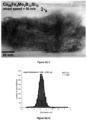
- Fig. 5e shows a further scanning electron micrograph of an Al 99 Si 1 -alloy metal fiber 2.
- the scale bar in the lower left corner of Fig. 5e indicates a length of 3 ⁇ m. In the micrograph shown in Fig.
- nanocrystalline domains can be recognized as grain structure.
- a scanning electron micrograph of a gold metal fiber 2 is shown in Fig. 5f ).
- the scale bar in the lower left corner of Fig. 5f ) indicates a length of 10 ⁇ m.
- nanocrystalline domains can be recognized as grain structure.
- Fig. 5g a scanning electron micrograph of an Cu 92 Sn 8 -alloy metal fiber 2 is shown.
- the scale bar in the lower left corner of Fig. 5g indicates a length of 1 ⁇ m.
- nanocrystalline domains can be recognized.
- Nanocrystalline domains can also be found in Cu 99 Si 4 -alloy metal fibers 2 produced by melt spinning, as can be recognized from the grain structure visible in the scanning electron micrograph of such a fiber 2 which is shown Fig. 5h .
- the scale bar in the lower left corner of Fig. 5h ) indicates a length of 1 ⁇ m.
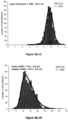
- Thicknesses and widths for 527 Al 99 Si 1 -alloy metal fibers 2 fabricated with a wheel-speed of 25 m/s are shown in the graph of Fig. 6a ).
- the corresponding thickness and width distributions are shown in the graphs of Fig. 6b) and 6c ), respectively. It can be recognized from Fig. 6a ) and b) that the Al 99 Si 1 -alloy metal fibers have a thickness in the range between 3 and 17 ⁇ m with a mean thickness of 8.5 ⁇ m.
- the thickness distribution follows a narrow Gaussian function, such as indicated by the line in Fig. 6b ).
- the width of the metal fibers is in a range of 5 to 80 ⁇ m, wherein the mean width is 39.5 ⁇ m and the median width is 35.0 ⁇ m.
- Figure 6d shows two DSC measurements. Curve I in Fig. 6d ) was obtained from CuSns microfibers directly after melt spinning and curve II in fig. 6d ) after thermal equilibration of the same microfibers. This demonstrates the exothermal process in case of heating melt spinned fibers in comparison to the equilibrated metal fibers.
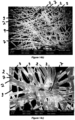
- a scanning electron micrograph of a network 6 of metal fibers 2 according to the invention is shown in Fig. 7 .
- the scale bar in the lower left corner of Fig. 7 indicates a length of 20 ⁇ m.
- the metal fibers 2 in the network 6 of Fig. 7 are amorphous metal fibers 2 of the Co 66 Fe 4 Mo 2 B 12 Si 16 -alloy.
- the metal fibers 2 are fixed to one another at points of contact 7, where the metal fibers 2 are sintered with one another.
- the metal fibers are fixed to one another, so that it is not possible to move these metal fibers 2 relative to one another and to separate one of the metal fibers 2 out of the network 6 without breaking the points of contact 7.
- the networks 6 of metal fibers 2 according to the invention have voids 9 in the form of pores between the metal fibers 2.
- points of contact 7 and voids 9 are indicated by reference signs in Fig. 7 .
- Reference signs for the voids 9 and also the points of contact 7 were omitted in Fig. 8 and 9 and also only some of the metal fibers 2 are indicated by reference signs.
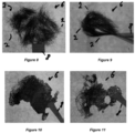
- FIG. 8 and 9 photographic images of another network 6 of amorphous metal fibers 2 of the Co 66 Fe 4 Mo 2 B 12 Si 16 -alloy are shown. It can be seen from these photographic images, that the network 6 can be held with tweezers 8 without separating metal fibers 2 from the network 6 of metal fibers 2 and that the network 6 is an unordered network 6, i.e. the metal fibers 2 do not have a preferred orientation but are oriented randomly.
- Fig. 8 and 9 show photographic images of the same network 6 of metal fibers 2.
- the network 6 as obtained after production is held with tweezers 8. It can be recognized from Fig. 9 that the network 6 can be bent and that the metal fibers 2 are still fixed to one another and are not separated from the network 6 of metal fibers 2.
- the network 6 of metal fibers 2 has a porous structure, with interconnected pores extending throughout the network of metal fibers.
- the points of contact 7 between the metal fibers 2 are distributed randomly throughout the network 6 of metal fibers 2.
- Photographic images of networks 6 of metal fibers 2 of copper are shown in Fig. 10 and 11 .
- the production of the network 6 shown in Fig. 10 is described in the following as Example 9 and the production of the network 6 shown in Fig. 11 is described in the following as Example 10. Accordingly, the network 6 shown in Fig. 10 has been produced at a higher temperature compared to the network 6 shown in Fig. 11 .
- both networks 6 show voids 9 in the form of pores distributed throughout the complete network 6, in the network 6 shown in Fig. 10
- the density of the pores i.e. number of pores per surface area, is lower at the center of the network 6 and increases towards the edges of the network 6.
- reference signs for the metal fibers 2 points of contact 7 and voids 9 were omitted in Fig. 10 and 11 .
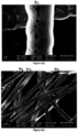
- Fig. 12 and 13 Scanning electron micrographs of the network shown in Fig. 11 are shown in Fig. 12 and 13 . Recording of the scanning electron micrographs was conducted similarly to the recording described above for the other scanning electron micrographs.
- the scale bar in the lower left corner of Fig. 12 indicates a length of 200 ⁇ m and the scale bar in the lower left corner of Fig. 13 indicates a length of 100 ⁇ m. It can be recognized from these scanning electron micrographs, that the structure of the copper metal fibers 2 was conserved, while the metal fibers 2 were sintered together at points of contact 7, so that they no longer form only an entangled network but are fixed to one another, so that it is no longer easily possible to separate single metal fibers 2 from the network 6 of metal fibers 2.
- voids 9 in the form of pores extend through the network 6 of metal fibers 2 and that the points of contact 7 are randomly distributed throughout the network 6.
- the stripes visible in the scanning electron micrographs of Fig. 12 and 13 result from discs of thermax alloy used for producing the network 6 of metal fibers 2, as described below for the Examples. These discs of the thermax alloy were cut and as a result have very fine grooves (not shown) on their surfaces which were imprinted onto the network of metal fibers during production using a hot press 10 as schematically shown in Fig. 15 .
- FIG. 14a A further photographic image of a network 6 of metal fibers 2 according to the invention is shown in Fig. 14a ).
- this network 6 of metal fibers 2 the metal fibers are made of a Cu 92 Sn 8 -alloy.
- the production of the network 6 shown in Fig. 14a ) is described in the following as Example 11.
- voids 9 in the form of pores are distributed throughout the complete network 6.
- the network 6 is an unordered network 6, i.e. the metal fibers 2 do not have a preferred orientation but are oriented randomly, with the metal fibers 2 being fixed to one another at points of contact 7, where the metal fibers 2 are sintered to one another.
- FIG. 14a For a better overview, reference signs for points of contact 7 and voids 9 were omitted in Fig. 14a ) and only some of the metal fibers 2 are indicated by reference signs in Fig. 14a ).
- the metal fibers 2, points of contact 7 and voids 9 can be recognized from the SEM images of Fig. 14b) and 14c ) which were taken from the network 6 shown in Fig. 14a ).
- the scale bar in the lower left corner of Fig. 14b ) indicates a length of 100 ⁇ m and the scale bar in the lower left corner of Fig. 14c ) indicates a length of 20 ⁇ m.
- FIG. 15 A schematic illustration of a hot press 10 is shown in Fig. 15 which can be used for producing the network 6 of metal fibers 2 according to the invention.
- the hot press 10 is provided with upper and lower parts 11 which can exert a force onto discs 12 between which metal fibers 2 are placed.
- the temperature at the site where the metal fibers 2 are located can be controlled. It is also possible to omit the discs 12 and to place the metal fibers 2 directly between the upper and lower parts 11.
- the discs 12 were made of a thermax alloy having fine grooves (not shown) on their surfaces. These fine grooves have a width in the range of 30 to 60 ⁇ m.
- a current collector 14 is provided as a first electrode.
- the current collector 14 is coated with an active electrode material 15.
- Lithium 16 is provided as electrolyte.
- an electrolyte is provided which impregnates all components of the batteries 13a and 13b and transports lithium ions.
- the current collector 14 is a network 6 of metal fibers 2 according to the invention, whereas in the battery 13b schematically shown in Fig. 16b ) the current collector 14 is a copper foil.
- the structure and composition of the batteries 13a and 13b are described in more detail below in the context of describing the Examples.
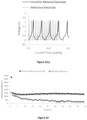
- the results of capacity measurement of the half-batteries 13a and 13b are shown in Fig. 17 .
- the battery according to the invention comprising the network of metal fibers has a capacity which is increased by around 50% compared to a reference battery comprising a copper foil instead of a network of metal fibers while keeping the composition and amount of active material constant for both half-batteries 13a and 13b.
- a further electrode was prepared using a network of metal fibers consisting of the copper alloy Cu 96 Si 4 .
- the network was infiltrated with a dispersion of 90% graphite and 10% binder, as further described below.
- a copper foil was coated with a 50 ⁇ m layer of the same dispersion using a doctor blade.
- Fig. 18 and 19 show plots of discharge profile obtained by chronopotentiometry for the inventive electrode having the network of metal fibers and of the reference cell.
- Fig. 20a shows a plot of charge discharge profile of an inventive network cell and of a reference cell obtained by chronopotentiometry with current normalized time. Enlarged views are provided in Fig. 21b ) and 21c ). The development of the capacity over the number of cycles for the inventive electrode and for the reference electrode is shown in Fig. 22 .
- a SEM image of the inventive electrode having a network of metal fibers consisting of the copper alloy Cu 96 Si 4 is provided. It can be seen from the SEM image that graphite flakes are within the metal fiber network, i.e. between the metal fibers.
- Fig. 23b shows an EDX mapping of copper for the inventive electrode shown in Fig. 23a)
- Fig. 23c shows an EDX mapping of carbon for the inventive electrode shown in Fig. 23a ).
- the EDX mapping demonstrates that the graphite is between the metal fibers.
- a melt spinning device using a range of experimental parameters was used to form the metal fibers.
- the device was composed of a massive wheel 3 (copper-alloy) of diameter 200 mm placed in a chamber with Argon atmosphere at a pressure of 300 mbar (all typical experimental settings).
- the wheel rotation-speed was increased up to 60 m/s.
- a pressure difference of up to 2000 mbar (or lower) between the crucible with nozzle and the surrounding chamber atmosphere triggered the ejection of the molten metal or metal alloy onto the rotating wheel-surface.
- microdroplets of melt were formed and were shaped as metal fibers in the shape of microribbons by rapid quenching (see Fig.
- melt spinning device for the melt spinning device used are disclosed in EP19175749.1 , WO2016/020493 A1 and in WO2017/042155 A1 .
- Each single microdroplet 5 was transformed into a single metal fiber 2 or multiple metal fibers 2.
- the deposition rate of the molten alloy onto the rotating wheel 3 was reduced to be in the range of 1.0 to 10.0 mg ⁇ s -1 or even lower. With such deposition rate, metal fibers 2 in the form of microribbons were formed in large quantities of up to 90-95% of the initial mass of molten alloy in the crucible.
- Optical images of the produced metal fibers 2 are shown in Fig. 2a ) to d) after rapid quenching and collection, the metal fibers 2 form an entangled network, wherein the metal fibers slide easily against each other so that it is easy to isolate one single metal fiber from this network.
- a typical initial mass of melt was in the range of 5 to 12 g (but can be increase to 100g).
- the distance between the nozzle 5 and the wheel surface was set in the range of 50 to 3000 ⁇ m, see Fig. 1b ) which shows a photographic image isolated from a movie taken at 40000 fps of depositing a Al 99 Si 1 -alloy melt onto the rotating wheel.
- the temperature of the melt was set in the range of 50 to 300°C above the melting temperature (higher processing temperatures are possible).
- the photographic images shown in Fig. 2a ) to d) and in Fig. 3a ) and b) were taken from correspondingly produced metal fibers.
- Metal fibers 2 in the form of microribbons were produced of Co, Cu, Al as well as alloys of these elements with other elements such as Co 66 Fe 4 Mo 2 B 12 Si 16 , Al 99 Si 1 (none comprehensive list).
- the metal fibers 2 made with pure Cu or the alloy Al 99 Si 1 had a polycrystalline structure of crystals with a maximum size up to 8 ⁇ m, as demonstrated by the X-ray diffraction spectra for the copper metal fibers 2 ( Fig. 4a )) and for the Al 99 Si 1 -alloy metal fibers 2 ( Fig. 4b )).
- the metal fibers 2 made with the Co 66 Fe 4 Mo 2 B 12 Si 16 -alloy had the typical structure of glassy metal, i.e. these metal fibers 2 were amorphous metal fibers 2, as can be seen from the X-ray diffraction spectrum of the Co 66 Fe 4 Mo 2 B 12 Si 16 -alloy metal fibers 2 depicted in Fig. 4c ).
- metal fibers 2 mainly composed of Al or Cu can be fabricated with a nanocrystalline or glassy metal structure (as observed for the Co-alloy Co 66 Fe 4 Mo 2 B 12 Si 16 ).
- the metal fibers 2 had the following typical dimensions: a width of 2.0 to 25.0 ⁇ m, a thickness of 1.0 to 7.0 ⁇ m and a length of 2.0 to 100.0 mm (see Fig. 3a ) and 3b )).
- the ribbon-thickness distributions were narrow Gaussian distributions with a standard deviation as small as 0.4 ⁇ m, i.e. 68% (resp. 95%) of the metal fibers 2 had a thickness within an interval (centered on the mean thickness) as narrow as 0.8 ⁇ m (resp. 1.6 ⁇ m). With a wheel-speed of 25 m/s, the ribbon mean thickness is 5.80 ⁇ m (see Fig.
- the fiber-width distributions were either Gaussian or log-normal distributions. With a wheel-speed of 25 m/s, the fiber mean width is 14.2 ⁇ m and the median width is 13.2 ⁇ m, i.e. 50% of the fiber have a width below 13.2 ⁇ m. When the wheel speed is doubled, the mean and median widths decrease to 9.4 ⁇ m, i.e. 50% of the fibers have a width below 9.4 ⁇ m.
- the mean and median thicknesses are 8.5 ⁇ 0.1 ⁇ m, i.e. 68% (resp. 95%) for the fibers and the fibers 2 had a thickness between 6.6 and 10.4 (resp. 4.8 and 12.2) ⁇ m.
- the mean width was 39.5 ⁇ 1.0 ⁇ m and the median width was 35.0 ⁇ 1.0 ⁇ m, i.e. 50% of the fibers had a width below 35.0 ⁇ m ( Fig. 6a ) to c)).
- SEM images for the Al 99 Si 1 -alloy metal fibers 2 are shown in Fig. 5c ) and 5d ), respectively.
- the dimensions of the copper metal fibers 2 were similar to the ones of the Al-alloy metal fibers (or smaller). SEM images for the copper metal fibers 2 are shown in Fig. 5a ) and 5b ). These SEM images demonstrate that the width of the metal fibers 2 remains constant over a length of at least 1mm (this is even true for length over 1cm). These ribbons have a crystalline structure: the observation of the top side, which was a liquid-gas interface before solidification upon rapid quenching, allows a direct visualization of the grains. The maximum size of the crystals is estimated to be in the range of 5-8 ⁇ m.
- the metal fibers 2 were used to produce networks 6 of metal fibers 2.
- Amorphous metal fibers 2 of Co 66 Fe 4 Mo 2 B 12 Si 16 produced by the melt spinning process described above were placed between two discs 12 of aluminum oxide with diameters of 45 mm.
- the staple of the discs 12 of aluminum oxide having a diameter of 45 mm and the metal fibers 2 was then placed into the 400 °C preheated hot press 10 and the fibers 2 were pressed at a predetermined pressure of 377 MPa for a predetermined time of 30 minutes, to avoid thermal expansion effects due to heating.
- the network 6 of Example 2 was prepared identical to the network 6 of Example 1, except that the pressure was reduced to 277 MPa.
- a SEM image of the network 6 of Example 2 is provided in Fig. 7 , as can be seen, the metal fibers 2 are sintered together and form a stable network 6. The SEM image shows that apart from the contact faces with the aluminum oxide disc 12, the texture and appearance of the metal fibers 2 was conserved.
- the network 6 of Example 3 was prepared identical to the network 6 of Example 1, except that instead of discs 12 of aluminum oxide discs 12 of a Thermax high-temperature alloy having diameters of 60 mm were used.
- the pressure applied was 283 MPa.
- the network 6 of Example 4 was prepared identical to the network 6 of Example 3, except that the time was reduced to 20 minutes.
- the network 6 of Example 5 was prepared identical to the network 6 of Example 3, except that the time was reduced to 10 minutes.
- the network 6 of Example 6 was prepared identical to the network 6 of Example 3, except that the time was reduced to 5 minutes.
- the network 6 of Example 7 was prepared identical to the network 6 of Example 3, except that the temperature was reduced 300 °C.
- amorphous metal fibers 2 of Co 66 Fe 4 Mo 2 B 12 Si 16 were placed in an oven and heated for 30 minutes to 600°C without applying external pressure. The fibers crystallized but did not sinter together.
- the network of Comparative Example 2 was prepared identical to the network 6 of Example 1, except that the pressure was reduced to 157 MPa.
- the network of Comparative Example 3 was prepared identical to the network 6 of Example 3, except that the pressure was reduced to 177 MPa.
- the network of Comparative Example 4 was prepared identical to the network 6 of Example 4, except that the temperature was reduced to 100 °C.
- the network of Comparative Example 5 was prepared identical to the network 6 of Example 4, except that the temperature was reduced to 200 °C.
- Table 1 summarizes the time, pressure and temperature used for the preparation of the networks of Examples 1 to 7 and Comparative Examples 1 to 5.
- Table 1 Parameter Example 1 Example 2
- Example 3 Example 4
- Example 5 Example 6
- Example 7 Comp.
- Example 1 Comp.
- Example 2 Comp.
- Example 3 Comp.
- Example 4 Comp.
- Example 5 time (min) 30 30 30 20 10 5 20 30 30 30 20 20 pressure (MPa) 377 220 283 283 283 283 283 283 283 283 ambient 157 177 283 283 temperature (°C) 400 400 400 400 400 400 400 300 600 400 400 100 200 network properties: network stability ++ ++ ++ ++ ++ ++ + ++ -- -- -- - amorphous fibers ++ ++ ++ ++ ++ ++ ++ ++ ++ ++ ++ ++ ++ ++ ++ ++ ++ ++ ++ ++ ++ ++ ++ ++ ++ ++ ++ ++ ++ ++ ++ ++ ++ ++ ++
- Comparative Example 2 time and temperature were identical to Examples 1 and 2. However, the network of Comparative Example 2 disintegrated when being removed from the press 10. This indicates that the pressure was not sufficient for sintering the amorphous Co 66 Fe 4 Mo 2 B 12 Si 16 -alloy metal fibers 2 to provide a fixation of the metal fibers 2 to one another. It can be concluded that the pressure is the driving force for the sintering of the metal fibers 2. Since amorphous materials have a lower density than crystalline materials, the atoms at the interphase are set into motion when pressure is applied. This causes these atoms to make a transition to an energetically preferred state in view of the pressure applied. As a result of the movement of the atoms, the metal fibers 2 are sintered together permanently.
- the networks 6 of metal fibers of Examples 3 to 5 did not show substantial differences. When shortening the time to only 5 minutes in Example 6, the fibers 2 were not fixed to each other as strong as in Examples 3 to 5. This demonstrates that the process of fixing the metal fibers 2 of the Co 66 Fe 4 Mo 2 B 12 Si 16 -alloy to one another has a certain time dependency but is finished within several minutes.
- the network 6 of Example 8 was prepared identical to the network 6 of Example 3, however, the temperature was set to 500 °C and the time was set to 20 minutes. In addition, in the network 6 of Example 8 more fibers 2 were used to obtain a network 6 having a thickness of 0.7 mm. After 20 minutes at a temperature of 500 °C under a pressure of 283 MPa, the network 6 of Example 8 was completely sintered, i.e. the stability of network 6 was comparable to that of Example 3.
- Fig. 8 an image of the network 6 of Example 8 is shown before deformation and in Fig. 9 an image of the network 6 of Example 8 in a deformed state is shown. Accordingly, it can be recognized from Fig. 9 that even when the network 6 is highly deformed, no metal fibers 2 are separated from the network 6. This indicates the formation of a highly stable network 6 that is not easily damaged by deformation.
- the network 6 of Example 9 was prepared identical to the network 6 of Example 3, however, instead of amorphous metal fibers 2 of Co 66 Fe 4 Mo 2 B 12 Si 16 , polycrystalline fibers 2 of copper (Cu) as described above were used, the time was set to 5 minutes, the pressure was set to 177 MPa and the temperature was set to 300 °C.
- amorphous metal fibers 2 of Co 66 Fe 4 Mo 2 B 12 Si 16 polycrystalline fibers 2 of copper (Cu) as described above were used, the time was set to 5 minutes, the pressure was set to 177 MPa and the temperature was set to 300 °C.
- the network 6 of Example 10 was prepared identical to the network 6 of Example 9, however, the time was set to 5 minutes.
- the network 6 of Comparative Example 6 was prepared identical to the network of Example 9, however, the time was set to 30 minutes and the temperature was set to 500 °C.
- Table 2 summarizes the time, pressure and temperature used for the preparation of the networks of Examples 9 and 10 and for Comparative Example 6.
- Table 2 Parameter Example 9 Example 10 Comp. Example 6 time (min) 5 3 30 pressure (MPa) 177 177 177 temperature (°C) 300 300 500 network properties: network stability ++ ++ ++ porosity + ++ --
- Comparative Example 6 the metal fibers could not be recognized in the sintered product and the obtained product was a copper foil. If a light source is placed behind the copper foil, a certain inhomogeneity could be recognized.
- the networks 6 of Examples 9 and 10 have a thickness from 0.15 mm up to 0.25 mm.
- FIG. 10 and 11 Images of the networks 6 of Examples 9 and 10 are shown in Fig. 10 and 11 , respectively. It can be seen from Fig. 10 that the network 6 of Example 9 has some areas in which the porosity is reduced. Particularly close to the edges of the network 6 of Example 9 many pores can be observed. By reducing the time from 5 to 3 minutes, the porosity was increased, as can be seen by the image of the network 6 of Example 10 provided in Fig.11 .
- SEM images of the network 6 of Example 10 are shown in Fig. 12 and 13 .
- the SEM images show the porous structure of the network 6 and that the metal fibers 2 are sintered together.
- the stripes which can be seen in Fig. 12 and 13 are produced by the surface of the discs 12 of Thermax high-temperature alloy used for pressing the metal fibers 2.
- the stripes in the discs of the Thermax high-temperature alloy are the result of cutting the Thermax high-temperature alloy.
- the copper metal fibers 2 show an improved capability to be sintered as a result of the high energy which is stored as a result of the fast cooling rates resulting from the melt-spinning process used for preparing the fibers.
- the melt spinning process provides cooling rates of up to 10 6 K ⁇ min -1 which freezes the movement of atoms of a system before they can arrange into energetically favored states.
- copper specific effects concerning atomic diffusion could play a role.
- metal fibers of the Cu-alloy Cu 92 Sn 8 were prepared analogously to the other metal fibers described above.
- the metal fibers of Cu-alloy Cu 92 Sn 8 were dispersed in 200 mL of demineralized water containing 50 mg of SDS (sodium dodecyl sulfate) and dried after vacuum filtration. In the entangled networks of metal fibers obtained this way, the metal fibers are distributed homogenously but are non-oriented.
- the staple of the discs 12 of thermax alloy having a diameter of 60 mm and the metal fibers 2 was then placed into the 300 °C preheated hot press 10 and the fibers 2 were pressed at a predetermined pressure of 78 MPa for a predetermined time of 3 minutes, to avoid thermal expansion effects due to heating.
- the network 6 of Example 11 has a thickness in the range from 0.15 mm up to 0.25 mm.
- a photographic image of the network 6 of Cu 92 Sn 8 metal fibers is shown in Fig. 14a ).
- SEM images of the network of Cu 92 Sn 8 metal fibers are shown in Fig. 14b) and Fig. 14c ).
- the network 6 of Comparative Example 7 was prepared identical to the network 6 of Example 11, however, the temperature was kept at room temperature, i.e. around 20 °C.
- the metal fibers were not sintered together and only a weak mechanical stability was observed.
- the mechanical stability is a result of the metal fibers being deformed due to the applied pressure but not as a result of a sintering of the metal fibers.
- the network 6 of Comparative Example 8 was prepared identical to the network 6 of Example 11, however, only a weak pressure of around 2 kPa was applied. There was no fixation between the metal fibers to one another obtained.
- Example 11 and Comparative Examples 7 and 8 that the combination of pressure and temperature is required to sinter the metal fibers to one another so that the metal fibers 2 are fixed to one another.
- the increased temperature promotes the atom movement in the direction of the pressure and therefore results in a sintering of the metal fibers 2 so that the metal fibers 2 are fixed to one another.
- Carding is a mechanical process that disentangles, cleans and intermixes fibers 2 to produce a continuous fleece 26.
- a scheme of a carding machine 24 is shown in Figure 24 .
- the continuous fleece 26 is obtained by passing the fibers 3 between differentially moving surfaces, e.g. rotating drums 28, covered with card clothing 30.
- the carding cloth 30 breaks up locks and unorganized clumps of fiber 2 and then aligns the individual fibers 2 to be parallel with each other. While carding is well known for wool it has not been used for organizing metallic fibers 2 to form a fleece 26.
- Figure 25 shows examples of fleece after carding.
- ca. 10 cm long, 30 ⁇ m wide and 2 ⁇ m thick fibers of brass as prepared by melt spinning are disentangled by a carding device. Two layers are formed which are stacked on top of each other. It may also stacked in between layers of cotton in order to form cotton/metallic hybrid fleece or tissue. Also combinations of cotton and metallic fiber nets can be disentangled by one carding step and form a cotton / metallic fiber hybrid fleece.
- Figure 25 shows photographic images of a manufacturing process according to the present invention.
- metallic fibers were disentangled by a carding device, as shown in the upper left image of Fig. 25 .
- Reference signs are not shown in Fig. 25 for a better overview.
- Next layer 1 and layer 2 of differently oriented fibers, as shown by the two middle photographs in the upper line of Fig. 25 were stacked on top of each other to provide a bilayered fleece, as sown in the upper right image of Fig. 25 .
- a cotton fleece such as the one shown in the lower right image of Fig. 25 can be integrated in metal fibers to provide a layered fleece, the upper side and underside of which are shown in the lower left and lower middle image in Fig. 25 .
- the clearly visible square shaped portion in the middle of the photographic image on the left side is an area in which the metal fibers 2 are fixed to one another via ultrasound welding, as described above.
- Images numbered with 1 to 3 in Fig. 26 are enlarged views of the sections indicated in the photographic image on the left side of Fig. 26 by corresponding boxes and numbers.
- the image beneath enlarged view number 1 is a further enlarged view corresponding to the box indicated in enlarged view number 1 and shows fixation of the metal fibers 2 to one another due to the applied ultrasound welding.
- Circular discs having diameters of 6 mm were cut from the network 6 of Example 10 and infiltrated with a dispersion of 80% SnO, 10% carbon black and 10% binder.
- the network 6 of sintered metal fibers 2 of copper acts as current collector 14.
- a copper foil was coated with a dispersion of 80% SnO, 10% carbon black and 10% binder to obtain a copper foil having a coated layer of active material on its surface.
- the thickness of the coating layer was adjusted to 50 ⁇ m by using tape casting.
- the copper foil acts as current collector 14.
- a half-cell 13a was assembled, as schematically shown in Fig. 16a ) including electrodes 14 and 15, separator 17 and Li-foil 16.
- the electrode described above as inventive electrode was used, i.e. the network 6 of Example 10 which is coated with an active electrode material 15.
- a further half-cell 13b was assembled, as schematically shown in Fig. 16b ).
- the electrode described above as non-inventive electrode was used, i.e. a copper foil coated with 50 ⁇ m active electrode material as described above.
- the amount of active electrode material 15 is increased in the reference half-cell 13b, i.e. a layer thicker than 50 ⁇ m is tape casted, the capacity drops, since the electrons have to pass through a thicker layer of active electrode material. It was found that by using the assembly shown in 13a, the amount of active electrode material could be increased by incorporating it into a conductive network by a factor of 60 compared to the standard assembly shown in 13b. Furthermore, it was possible to obtain a homogenous charge distribution throughout the electrode by using a metal fiber network and it was further possible to significantly increase the capacity per mass unit.
- FIG. 17 A comparison of the capacity of these two half-cells 13a, 13b is provided in Fig. 17 .
- the capacity for the half-cell 13a (according to the invention) is increased by almost 50% compared to the reference half-cell 13b.
- the capacity measurements were conducted using a Metrohm M204 electrochemical measurement system run with the software NOVA Battery 1.0.
- the cell was assembled in a Swagelok TM type cell, using lithium foil (Sigma Aldrich (99.8 wt%) as counter electrode, separion polymer v though (Sigma Aldrich, Whatman ® glass microfiber filters, Grade 934-AH ® ) as separator and 1 M LiClO 4 (Sigma Aldrich) dissolved in 1:1 EC/DMC (Ethylcarbonate/Dimethylcarbonate (ALFA AESAR)) as electrolyte.
- a constant current of 100 mAh/g was applied, normalized to the amount of active material used for the respective electrode.
- the potential was simultaneously measured and as vortex points for the potential 0.0125 V (lower vortex point) and 2.2 V (higher vortex point) were measured.
- the resulting set of data points includes values for the potential at any given point of time. Since a constant current is supplied, the capacity can then be calculated by multiplying the time between lower (completely discharged) and higher vortex point (completely charged) with the applied current.
- the graphite and binder used were the following:
- the capacity measurements were conducted using a Metrohm M204 electrochemical measurement system run with the software NOVA Battery 1.0.
- the cell was assembled in a Swagelok TM type cell, using lithium foil (Sigma Aldrich (99.8 wt%) as counter electrode, glas fiber (Sigma Aldrich, Whatman ® glass microfiber filters, Grade 934-AH ® ) as separator and EC:DMC (1M LiPF 6 ) as electrolyte (EC: ethylene carbonate; DMC: dimethyl carbonate).
- a constant current of 382 mA/g was applied, normalized to the amount of active material used for the respective electrode.
- the potential was simultaneously measured and as vortex points for the potential 0.0125 V (lower vortex point) and 2.2 V (higher vortex point) were measured.
- the resulting set of data points includes values for the potential at any given point of time. Since a constant current is supplied, the capacity can then be calculated by multiplying the time between lower (completely discharged) and higher vortex point (completely charged) with the applied current.
- the inventive network electrode is more electrochemically stable than the common reference electrode with a nearly constant capacity over 50 cycles whilst using the same active material. This is related to the 3D network of the inventive electrode, which supports the effective distribution of the stress formed within the active material due to swelling during ion intercalation. Upon intercalation of Lithium ions the active material undergoes swelling (up to 8 vol% for graphite), which leads to a decrease of capacity over cycling in the reference cell.
- the electronic conductivity is improved by the inventive metal fiber network used as current collector.
- the network improves the electrode conductivity by shortening the electron conduction path compared to the reference electrode where the conductivity gradient is present through the electrode.
- the inventive electrode it was possible to charge and discharge the half-cell 50 times within 6 hours compared to the reference electrode, which was charged 50 times in 16 hours.
- the capacity for the inventive network electrode could be preserved (1492 mAh/m 2 ⁇ 1381mAh/m 2 ), which was not the case for the reference electrode (1183 mAh/m 2 ⁇ 289 mAh/m 2 ).
- Figure 18 and 19 present plots of charge discharge profiles of the reference cell and the inventive network cell respectively.
- Figure 20a) and 20b presents the first and last cycle of the same measurement.
- Figure 21a) to 21c present the charge discharge profiles with a current normalized time for a better view of the changes while the cyclization.
- Figure 22 presents the capacity over the cycles.
- Figure 23a presents a cross section SEM image of the inventive network electrode, which visualizes graphite flakes between the copper fibers.
- fibers of CuSi4, Al99Si1, Cu92Sn8, Co 66 Fe 4 Mo 2 B 12 Si 16 and FeNiB were produced using the above described method.
- the alloys listed in Table 3 were thermally pretreated with the parameters also listed in Table 3 in order to reduce the stored defect energy, but without causing a change in the grain structure caused by recrystallization.
- the amorphous/nanocrystalline fibers were additionally thermally treated above the crystallization temperature to investigate the difference in the microstructural state.
- Parts of the fibres in each state were melted twice with a Netzsch STA 449 F3 under argon atmosphere.
- Thermal pretreatment was performed using the parameters described in Table 3 using also the Netzsch STA 449 F3. All samples were heated at a constant heating and cooling rate of 10 K/min from 30 °C to 1200 °C or 900 °C, respectively, in the case of Al 99 Si 1 , and then cooled down again to 30 °C. The samples were then heated to 1200 °C or 900 °C, respectively. The temperature was kept at 30 °C for 1 h between the individual melting steps or where applicable between thermal treatment and melting.
- the measurement could be adjusted so that only the pure energy quantity of the fibers was measured.
- the difference of the area integrals between the measurements with and without thermal pretreatment corresponds to the stored defect energy or crystallization energy.
- the amount of stored energy is shown in Table 4 as defective energy and crystallization energy. No energy could be determined for CuSi 4 because during thermal pretreatment the fibers were transferred into a thermodynamically stable phase with a two-phase structure. Due to the resulting two-phase structure, a correct measurement of the stored defect energy is not possible.
- metal fibers obtained by melt spinning have a significant amount of stored energy in form of defective energy and/or crystallization energy, i.e. these fibers are not in their thermodynamic equilibrium.
- metal fibers of this alloy have a significant amount of defective energy; however, it is not possible to make a meaningful quantification thereof, since the material is transferred into a state of thermodynamic equilibrium when subjected to the thermal pretreatment conditions specified in table 3.
- the combined amount of defective energy and crystallization energy for Cu 96 Si 4 is estimated to be around 2.3 kJ/g.
- the fibers were then weighed against the values given in Table 5 and wet laid to form uniform non-woven structures thereof. These were then sintered using pressure-induced low-temperature sintering as described above for Example 1 with the parameters also listed in Table 5. Before sintering, the electrical conductivity of the non-woven structures of the copper and aluminium alloy fibres was determined by means of a 4-point measurement and an impedance measurement. These measurements were repeated after sintering. The measured values before and after sintering are listed in Table 6. Table 5: Initial weights and pressure sintering parameters.
- the conductivity of the sintered samples is many times higher than that of the unsintered samples. It is worth mentioning that the distance between the contacts which was used to measure the material's conductivity was only a 5 mm in the case of the loose fibers (before sintering). Increasing the distance between these contacts increased the resistance to more than 100 fold. This results from the non-sintered fibers which do not form a stable conductivity in between fibers. Contrary, while increasing the distance between contacts in case of sintered networks the conductivity was barely depending on the distance. This is because of the high conductivity in between fibers due to sintering.
- Table 7 Mechanical stability of sintered fiber networks material Untreated fibers, as obtained from the melt spinning process Fibers subjected to conditions in table 3 before sintering
- Young's modulus [N] CuSi 4 12.5 1741 8.1 1151 Al 99 Si 1 7.1 1118 0.4 2.3
- the Battery production consists of 7 process steps:
- step 1 shows production of metal fibers
- step 2 shows arranging of fiber nets for layer fiber fleece
- step 3 shows different sintering methods of metal fibers for the formation of a mechanically stable metal fiber network.
- Sintering can be performed by pressure induced low temperature sintering (part c1) or by thermal sintering (part c2), ultrasound welding (part c3) or hammering (part c4).
- part d the anode and cathode are formed by loading the metal fiber network with active material (step 4).
- the electrodes are densified in part e using calendering (step 5).
- step 5 As a next step, a conductive foil is attached onto the network of metal fibers in step 6. Battery assembly is shown in step 7 of Fig. 27 .
- Metal fibers are produced by melt spinning.
- Two principal different melt spinning technologies can be used to produce metal fibers: a) vertical melt spinner, b) horizontal melt spinner; the vertical melt spinner has technical limitations which makes the product more expensive and less efficient compared to production using a horizontal melt spinner. Therefore, the horizontal melt spinner is preferably used in the present invention.
- the metallic fibers are treated much like cotton for textiles - the reason why the resulting net can be referred to as a metallic textile.
- the metallic "wool" is disentangled and the fibers aligned by carding, such as schematically shown in Fig. 24 .
- This step requires microfibers of substantial length.
- the fibers are carded by a carding comb, as known in the art of cotton treatment, to obtain a homogenous fiber network structure and such ordered layers are stacked on top of each one.
- the fibers preferably have a length of 5 - 18 cm and have no connections between them before carding. In this step no liquid dispersion step is necessary. Avoiding liquid dispersions is possible due to the long extension of the fibers.
- non-ordered fiber nets are produced by deposition from liquid dispersions or from air flow (step 2, b2).
- Step 3 Sintering of metal fibers for the formation of a 3D metal fiber nets
- the uniform fiber network structure can be sintered between two heating plates (distance adjustable between 0.2 - 1 mm, here 0.5 mm; Al 99 Si 1 at 650 °C for 1.5 h; C U96 Si 4 at 950 °C for 2h), such as schematically shown in steb 3, c2 of Fig. 27 .
- the 3D metal fiber net is pressure-sintered between 2 thermo plates.
- the fibers are placed on two polished thermo plates and pressed 1 min with an pressure of 10 GPa at 150 °C for Al 99 Si 1 and 300 °C for Cu 96 Si 4 in a preheated uniaxial press, such as schematically shown in step 3, c1 of Fig. 27 .
- the mechanical stable 3D fiber-network can be easily zipped off from the substrate.
- metal fibers are locally fixed by ultrasound welding ( Fig. 27 , step 3, c3) or hammering ( Fig. 27 , step 3, c4).
- Step 4 Formation of anode and cathode by loading the 3D metal fiber net with electrode active material
- the active material used in the examples is commercially available from Custom Cells as a slurry. Graphite was used for the Anode side and NMC_111 for the cathode side.
- the 3D metal fiber net was loaded with a slurry of active material, such as illustrated in Fig. 27 , step 4, d.
- a siliconized PMMA foil was placed onto the plate, wetted before with ethanol/acetone. After flattening the foil, the sintered fiber network was placed onto the foil. Then, the rather liquid slurry of active material was drop-casted onto the 3D metal fiber net.
- the 3D metal fiber net structure offers capillary forces which pulled the slurry into the network and coated it homogenously. The, more viscous slurry was poured onto the network and the gap doctor blade was used to remove residual slurry (height 0.650 mm). Subsequently, the samples were dried (Anode at RT and Cathode at 30 °C).
- the 3D metal fiber network was formed without being in contact with active material, i.e. the active materials were applied onto the networks of metal fibers after sintering of these networks was completed.
- FIG. 27 A schematic illustration of such a calendering process is illustrated in Fig. 27 , step 5, e.
- Step 6 Ultrasound welding of conductive foil on electrode
- Ni foil was attached to the side of an electrode by ultrasound welding. These Ni foils were the contact electrodes of the battery. Ultrasound welding of contact electrodes to the network 6 is schematically illustrated in Fig. 27 , step 6, f.
- the packaging of the 3D metal fiber networks started with punching out the active material loaded electrodes in the desired dimension / geometry.
- the samples were placed into a uniaxial press and punched out in the desired form.
- the samples were glued using PVDF Binder in acetone onto the respective sides of a separator (PP/PE stretched), which was punched out beforehand with an overlap of 1 - 2 mm in order to avoid internal shorting of the electrodes.
- they were placed into the laminated pouch and dried at 110 °C for 48 h in a furnace.
- the samples were transferred into a glovebox, filled with electrolyte (EC/DMC, 1 M LlPF 6 ) and sealed in order to ensure an airtight packaging.
- the surplus of electrolyte was removed using a syringe and a vacuum pump with a liquid filter and sealed again tightly directly below the electrode.
- Table 8 values for gravimetric capacity and gravimetric energy density Inventive battery comparative battery gravimetric capacity 140 Ah/kg (0.1C) 63 Ah/kg (0.1C) 135 Ah/kg (0.5C) 52 Ah/kg (0.5C) 67 Ah/kg (1C) 29 Ah/kg (1C) gravimetric energy density 519 Wh/kg (0.1C) 233 Wh/kg (0.1C) 499 Wh/kg (0.5C) 196 Wh/kg (0.5C) 249 Wh/kg (1C) 107 Wh/kg (1C) Table 9: values for volumetric capacity and volumetric energy density Inventive battery comparative battery volumetric capacity 87 Ah/I (0.1C) 28 Ah/I (0.1C) 81 Ah/I (0.5C) 24 Ah/I (0.5C) 41 Ah/I (1C) 18
Landscapes
- Chemical & Material Sciences (AREA)
- Engineering & Computer Science (AREA)
- Chemical Kinetics & Catalysis (AREA)
- General Chemical & Material Sciences (AREA)
- Electrochemistry (AREA)
- Materials Engineering (AREA)
- Manufacturing & Machinery (AREA)
- Mechanical Engineering (AREA)
- Metallurgy (AREA)
- Organic Chemistry (AREA)
- Nanotechnology (AREA)
- Crystallography & Structural Chemistry (AREA)
- Powder Metallurgy (AREA)
- Cell Electrode Carriers And Collectors (AREA)
- Battery Electrode And Active Subsutance (AREA)
- Inert Electrodes (AREA)
- Fuel Cell (AREA)
- Nonwoven Fabrics (AREA)
- Chemical Or Physical Treatment Of Fibers (AREA)
Applications Claiming Priority (3)
| Application Number | Priority Date | Filing Date | Title |
|---|---|---|---|
| EP18183945.7A EP3598526A1 (fr) | 2018-07-17 | 2018-07-17 | Réseau de fibres métalliques, procédé de production d'un réseau de fibres métalliques électrode et batterie |
| EP19749213.5A EP3821482B1 (fr) | 2018-07-17 | 2019-07-16 | Réseau de fibres métalliques, procédé de production d'un réseau de fibres métalliques électrode et batterie |
| PCT/EP2019/069144 WO2020016240A1 (fr) | 2018-07-17 | 2019-07-16 | Réseau de fibres métalliques, procédé de fabrication d'un réseau de fibres métalliques, électrode et batterie |
Related Parent Applications (1)
| Application Number | Title | Priority Date | Filing Date |
|---|---|---|---|
| EP19749213.5A Division EP3821482B1 (fr) | 2018-07-17 | 2019-07-16 | Réseau de fibres métalliques, procédé de production d'un réseau de fibres métalliques électrode et batterie |
Publications (2)
| Publication Number | Publication Date |
|---|---|
| EP4224545A2 true EP4224545A2 (fr) | 2023-08-09 |
| EP4224545A3 EP4224545A3 (fr) | 2024-07-17 |
Family
ID=62981089
Family Applications (3)
| Application Number | Title | Priority Date | Filing Date |
|---|---|---|---|
| EP18183945.7A Withdrawn EP3598526A1 (fr) | 2018-07-17 | 2018-07-17 | Réseau de fibres métalliques, procédé de production d'un réseau de fibres métalliques électrode et batterie |
| EP19749213.5A Active EP3821482B1 (fr) | 2018-07-17 | 2019-07-16 | Réseau de fibres métalliques, procédé de production d'un réseau de fibres métalliques électrode et batterie |
| EP22206199.6A Pending EP4224545A3 (fr) | 2018-07-17 | 2019-07-16 | Réseau de fibres métalliques, procédé de fabrication d'un réseau de fibres métalliques, électrode et batterie |
Family Applications Before (2)
| Application Number | Title | Priority Date | Filing Date |
|---|---|---|---|
| EP18183945.7A Withdrawn EP3598526A1 (fr) | 2018-07-17 | 2018-07-17 | Réseau de fibres métalliques, procédé de production d'un réseau de fibres métalliques électrode et batterie |
| EP19749213.5A Active EP3821482B1 (fr) | 2018-07-17 | 2019-07-16 | Réseau de fibres métalliques, procédé de production d'un réseau de fibres métalliques électrode et batterie |
Country Status (8)
| Country | Link |
|---|---|
| US (2) | US12489135B2 (fr) |
| EP (3) | EP3598526A1 (fr) |
| JP (1) | JP7760368B2 (fr) |
| KR (1) | KR102749409B1 (fr) |
| CN (1) | CN112740444B (fr) |
| ES (1) | ES2936626T3 (fr) |
| PL (1) | PL3821482T3 (fr) |
| WO (1) | WO2020016240A1 (fr) |
Families Citing this family (16)
| Publication number | Priority date | Publication date | Assignee | Title |
|---|---|---|---|---|
| CN111540607B (zh) * | 2020-05-29 | 2022-01-14 | 东莞东阳光科研发有限公司 | 电极结构材料及制备电极结构材料的方法、电解电容器 |
| EP3944914A1 (fr) * | 2020-07-30 | 2022-02-02 | Max-Planck-Gesellschaft zur Förderung der Wissenschaften e.V. | Buse et procédé de formation de microgouttelettes |
| EP4000710A1 (fr) * | 2020-11-20 | 2022-05-25 | Max-Planck-Gesellschaft zur Förderung der Wissenschaften e.V. | Filtre |
| WO2022237966A1 (fr) * | 2021-05-11 | 2022-11-17 | MAX-PLANCK-Gesellschaft zur Förderung der Wissenschaften e.V. | Réseau de fibres métalliques et procédé d'assemblage d'un réseau de fibres |
| JP2024516898A (ja) * | 2021-05-11 | 2024-04-17 | マックス-プランク-ゲゼルシャフト ツア フェーデルンク デア ヴィッセンシャフテン エー.ファオ. | 電極及び電池 |
| EP4342009A4 (fr) * | 2021-05-21 | 2025-07-23 | Applied Materials Inc | Production à grand volume d'anodes en alliage pour batterie li-ion |
| CN113245684A (zh) * | 2021-05-28 | 2021-08-13 | 中国石油化工股份有限公司 | 金属微纤材料及其定型方法、制备方法和应用 |
| EP4106037A1 (fr) | 2021-06-16 | 2022-12-21 | Max-Planck-Gesellschaft zur Förderung der Wissenschaften e.V. | Procédé de production d'une électrode, électrode, composition de revêtement à sec, batterie et circuit électronique |
| CN118355516A (zh) | 2021-12-07 | 2024-07-16 | 马克斯·普朗克科学促进学会 | 锂金属电极、制造锂离子电极的方法及锂离子电池 |
| CN114603148B (zh) * | 2022-05-11 | 2022-07-05 | 成都大学 | 一种球形合金粉末的制备装置及制备方法 |
| EP4368384A1 (fr) | 2022-11-11 | 2024-05-15 | batene GmbH | Structure de réseau composite |
| EP4368314A1 (fr) * | 2022-11-11 | 2024-05-15 | batene GmbH | Réseau tridimensionnel de fibres métalliques et procédé de production |
| CN115874351A (zh) * | 2022-12-12 | 2023-03-31 | 江苏亨通精密铜业有限公司 | 非织造复合箔、制备工艺及其应用 |
| EP4438783A1 (fr) | 2023-03-27 | 2024-10-02 | batene GmbH | Réseau tridimensionnel (3d) de fibres métalliques et procédé de production |
| EP4624071A1 (fr) | 2024-03-26 | 2025-10-01 | Max-Planck-Gesellschaft zur Förderung der Wissenschaften e.V. | Fibre métallique |
| EP4650503A1 (fr) | 2024-05-15 | 2025-11-19 | batene GmbH | Réseau tridimensionnel de fibres métalliques et procédé de production |
Citations (4)
| Publication number | Priority date | Publication date | Assignee | Title |
|---|---|---|---|---|
| WO2016020493A1 (fr) | 2014-08-07 | 2016-02-11 | MAX-PLANCK-Gesellschaft zur Förderung der Wissenschaften e.V. | Appareil et procédé de fabrication de brins métalliques ou inorganiques ayant une épaisseur dans la plage micrométrique par filage en fusion |
| WO2017042155A1 (fr) | 2015-09-11 | 2017-03-16 | MAX-PLANCK-Gesellschaft zur Förderung der Wissenschaften e.V. | Appareil et procédé de fabrication de fibres métalliques ou inorganiques ayant une épaisseur de l'ordre du micromètre par filage en fusion |
| WO2017222895A1 (fr) | 2016-06-23 | 2017-12-28 | Government Of The United States As Represented By The Secretary Of The Air Force | Batteries flexibles, pliables et imprimables ayant une sécurité améliorée et une meilleure stabilité à température élevée, leurs procédés de fabrication et leurs procédés d'utilisation |
| WO2018048166A1 (fr) | 2016-09-09 | 2018-03-15 | 주식회사 엘지화학 | Électrode comprenant un collecteur de courant d'électrode de structure de réseau tridimensionnel |
Family Cites Families (15)
| Publication number | Priority date | Publication date | Assignee | Title |
|---|---|---|---|---|
| CA1264674A (fr) * | 1984-10-17 | 1990-01-23 | Paul Ducheyne | Materiau de fibres metalliques souples et poreuses pour la fabrication d'implants chirurgicaux |
| US5518833A (en) * | 1994-05-24 | 1996-05-21 | Eagle-Picher Industries, Inc. | Nonwoven electrode construction |
| JPH09143510A (ja) * | 1995-11-14 | 1997-06-03 | Kataoka Tokushu Kogyo Kk | 電池電極基板用金属繊維多孔体、電池電極板およびその製造方法 |
| JPH09161807A (ja) * | 1995-12-06 | 1997-06-20 | Wakamatsu Netsuren Kk | リチウムイオン電池の電極基体 |
| US20020168574A1 (en) * | 1997-06-27 | 2002-11-14 | Soon-Ho Ahn | Lithium ion secondary battery and manufacturing method of the same |
| US8277711B2 (en) * | 2007-03-29 | 2012-10-02 | E I Du Pont De Nemours And Company | Production of nanofibers by melt spinning |
| JP5548578B2 (ja) * | 2010-10-15 | 2014-07-16 | 日本発條株式会社 | 高強度マグネシウム合金線材及びその製造方法、高強度マグネシウム合金部品、並びに高強度マグネシウム合金ばね |
| KR101088073B1 (ko) * | 2010-10-16 | 2011-12-01 | 주식회사 샤인 | 금속 장섬유를 포함하는 전극 구조를 갖는 전지 및 이의 제조 방법 |
| KR101375158B1 (ko) | 2011-11-17 | 2014-03-17 | 주식회사 샤인 | 전극 조립체, 이의 제조 방법, 및 전지의 충전 및 방전 방법 |
| KR101666699B1 (ko) * | 2013-06-24 | 2016-10-14 | 주식회사 제낙스 | 이차 전지용 집전체 및 이를 이용한 전극 |
| US9853324B2 (en) * | 2013-09-11 | 2017-12-26 | Arizona Board Of Regents On Behalf Of Arizona State University | Nanowire-based solid electrolytes and lithium-ion batteries including the same |
| EP3367486B1 (fr) * | 2015-10-20 | 2020-08-19 | I&T New Materials Co., Ltd. | Élément à base de fibres non tissées d'aluminium pour collecteur de dispositif de stockage de puissance, son procédé de fabrication, électrode utilisant ledit élément à base de fibres non tissées d'aluminium et son procédé de fabrication |
| EP3185335B1 (fr) * | 2015-12-21 | 2020-02-05 | The Swatch Group Research and Development Ltd. | Batterie |
| CN105642019A (zh) * | 2016-03-31 | 2016-06-08 | 朗天科技股份有限公司 | 一种高温除尘滤料及其制备方法 |
| KR102027964B1 (ko) | 2017-07-17 | 2019-10-04 | 한국과학기술원 | 탄화수소 개질용 촉매 |
-
2018
- 2018-07-17 EP EP18183945.7A patent/EP3598526A1/fr not_active Withdrawn
-
2019
- 2019-07-16 EP EP19749213.5A patent/EP3821482B1/fr active Active
- 2019-07-16 WO PCT/EP2019/069144 patent/WO2020016240A1/fr not_active Ceased
- 2019-07-16 ES ES19749213T patent/ES2936626T3/es active Active
- 2019-07-16 US US17/260,420 patent/US12489135B2/en active Active
- 2019-07-16 KR KR1020217004330A patent/KR102749409B1/ko active Active
- 2019-07-16 CN CN201980060634.7A patent/CN112740444B/zh active Active
- 2019-07-16 JP JP2021502592A patent/JP7760368B2/ja active Active
- 2019-07-16 PL PL19749213.5T patent/PL3821482T3/pl unknown
- 2019-07-16 EP EP22206199.6A patent/EP4224545A3/fr active Pending
-
2025
- 2025-08-13 US US19/298,260 patent/US20260106206A1/en active Pending
Patent Citations (4)
| Publication number | Priority date | Publication date | Assignee | Title |
|---|---|---|---|---|
| WO2016020493A1 (fr) | 2014-08-07 | 2016-02-11 | MAX-PLANCK-Gesellschaft zur Förderung der Wissenschaften e.V. | Appareil et procédé de fabrication de brins métalliques ou inorganiques ayant une épaisseur dans la plage micrométrique par filage en fusion |
| WO2017042155A1 (fr) | 2015-09-11 | 2017-03-16 | MAX-PLANCK-Gesellschaft zur Förderung der Wissenschaften e.V. | Appareil et procédé de fabrication de fibres métalliques ou inorganiques ayant une épaisseur de l'ordre du micromètre par filage en fusion |
| WO2017222895A1 (fr) | 2016-06-23 | 2017-12-28 | Government Of The United States As Represented By The Secretary Of The Air Force | Batteries flexibles, pliables et imprimables ayant une sécurité améliorée et une meilleure stabilité à température élevée, leurs procédés de fabrication et leurs procédés d'utilisation |
| WO2018048166A1 (fr) | 2016-09-09 | 2018-03-15 | 주식회사 엘지화학 | Électrode comprenant un collecteur de courant d'électrode de structure de réseau tridimensionnel |
Non-Patent Citations (1)
| Title |
|---|
| HENRIK DOMMES: "Vom Faserabfall zum hochwertigen Leichtbau Halbzeug", LIGHT WEIGHT DESIGN, vol. 3, 2010, pages 23 - 27 |
Also Published As
| Publication number | Publication date |
|---|---|
| KR20210033006A (ko) | 2021-03-25 |
| US20260106206A1 (en) | 2026-04-16 |
| PL3821482T3 (pl) | 2023-03-20 |
| CN112740444A (zh) | 2021-04-30 |
| EP3821482A1 (fr) | 2021-05-19 |
| WO2020016240A1 (fr) | 2020-01-23 |
| EP3821482B1 (fr) | 2022-11-16 |
| EP3598526A1 (fr) | 2020-01-22 |
| JP7760368B2 (ja) | 2025-10-27 |
| US12489135B2 (en) | 2025-12-02 |
| KR102749409B1 (ko) | 2024-12-31 |
| US20210265636A1 (en) | 2021-08-26 |
| JP2021530631A (ja) | 2021-11-11 |
| CN112740444B (zh) | 2026-02-13 |
| ES2936626T3 (es) | 2023-03-21 |
| EP4224545A3 (fr) | 2024-07-17 |
Similar Documents
| Publication | Publication Date | Title |
|---|---|---|
| EP3821482B1 (fr) | Réseau de fibres métalliques, procédé de production d'un réseau de fibres métalliques électrode et batterie | |
| KR101594836B1 (ko) | 그래핀-금속나노입자복합체, 상기 복합체를 포함하는 탄소나노섬유복합체 및 상기 탄소나노입자복합체를 포함하는 이차전지 | |
| JP2022062091A (ja) | 電池用の固体カソライト又は電解質 | |
| EP2885832B1 (fr) | Procédé de formation d'une connexion électrique à une électrode à fibre conductrice et électrode ainsi formée | |
| Dimesso et al. | LiFePO4–3D carbon nanofiber composites as cathode materials for Li-ions batteries | |
| KR101747938B1 (ko) | 고체전해질 복합체, 및 이를 포함하는 전고체전지 | |
| KR101348200B1 (ko) | 실리콘 또는 실리콘산화물을 포함하는 실리콘계 탄소나노섬유복합체, 상기 복합체 제조방법 및 상기 복합체를 포함하는 리튬이차전지 | |
| CN117321797A (zh) | 复合体粒子、负极合剂层及锂离子二次电池 | |
| Sun et al. | Graphene-oxide-wrapped ZnMn2O4 as a high performance lithium-ion battery anode | |
| CN118805269A (zh) | 用于干电极的混合物粉末和包括该混合物粉末的用于电化学装置的干电极 | |
| HK40042873B (en) | Network of metal fibers, method for producing a network of metal fibers, electrode and battery | |
| HK40042873A (en) | Network of metal fibers, method for producing a network of metal fibers, electrode and battery | |
| Yue et al. | Freestanding hybrid electrospun membranes consisting of TiO2 nanotube-core nanocarbon as high-performance and long-lifespan anodes for lithium-ion batteries | |
| Huang et al. | Three-dimensional porous composite framework assembled with CuO microspheres as anode current collector for lithium-ion batteries | |
| EP4368314A1 (fr) | Réseau tridimensionnel de fibres métalliques et procédé de production | |
| JPH0969362A (ja) | 二次電池及び二次電池を用いた電源 | |
| CN116235312A (zh) | 锂离子二次电池用负极合剂及锂离子二次电池 | |
| EP4427276A1 (fr) | Électrode au lithium-métal, procédé de fabrication d'une électrode au lithium-ion et batterie au lithium-ion | |
| EP4632766A1 (fr) | Feuille d'électrolyte solide et son procédé d'évaluation | |
| EP4368384A1 (fr) | Structure de réseau composite | |
| Yella et al. | Modern Solvothermally Synthesized Bismuth Telluride Hexagonal Platelets As An Efficient Anode Material For Lithium-And Sodium-Ion Batteries | |
| Peng et al. | Journal of Materiomics | |
| Xie et al. | Preparation of Nano-Sized Cr2gac Confined in Carbonaceous Nanowires and its Application in Lithium-Ion Batteries |
Legal Events
| Date | Code | Title | Description |
|---|---|---|---|
| PUAI | Public reference made under article 153(3) epc to a published international application that has entered the european phase |
Free format text: ORIGINAL CODE: 0009012 |
|
| STAA | Information on the status of an ep patent application or granted ep patent |
Free format text: STATUS: THE APPLICATION HAS BEEN PUBLISHED |
|
| AC | Divisional application: reference to earlier application |
Ref document number: 3821482 Country of ref document: EP Kind code of ref document: P |
|
| AK | Designated contracting states |
Kind code of ref document: A2 Designated state(s): AL AT BE BG CH CY CZ DE DK EE ES FI FR GB GR HR HU IE IS IT LI LT LU LV MC MK MT NL NO PL PT RO RS SE SI SK SM TR |
|
| REG | Reference to a national code |
Ref country code: DE Ref legal event code: R079 Free format text: PREVIOUS MAIN CLASS: H01M0004040000 Ipc: B22F0001062000 |
|
| PUAL | Search report despatched |
Free format text: ORIGINAL CODE: 0009013 |
|
| AK | Designated contracting states |
Kind code of ref document: A3 Designated state(s): AL AT BE BG CH CY CZ DE DK EE ES FI FR GB GR HR HU IE IS IT LI LT LU LV MC MK MT NL NO PL PT RO RS SE SI SK SM TR |
|
| RIC1 | Information provided on ipc code assigned before grant |
Ipc: B22F 1/16 20220101ALI20240612BHEP Ipc: B22F 1/08 20220101ALI20240612BHEP Ipc: H01M 4/80 20060101ALI20240612BHEP Ipc: H01M 10/052 20100101ALI20240612BHEP Ipc: H01M 4/04 20060101ALI20240612BHEP Ipc: H01M 4/75 20060101ALI20240612BHEP Ipc: B22F 1/062 20220101AFI20240612BHEP |
|
| STAA | Information on the status of an ep patent application or granted ep patent |
Free format text: STATUS: REQUEST FOR EXAMINATION WAS MADE |
|
| 17P | Request for examination filed |
Effective date: 20250116 |