EP4331723A1 - Ensemble comprenant une microplaque, un couvercle et un dispositif de libération d'une liaison encliquetable entre la microplaque et le couvercle - Google Patents
Ensemble comprenant une microplaque, un couvercle et un dispositif de libération d'une liaison encliquetable entre la microplaque et le couvercle Download PDFInfo
- Publication number
- EP4331723A1 EP4331723A1 EP22193653.7A EP22193653A EP4331723A1 EP 4331723 A1 EP4331723 A1 EP 4331723A1 EP 22193653 A EP22193653 A EP 22193653A EP 4331723 A1 EP4331723 A1 EP 4331723A1
- Authority
- EP
- European Patent Office
- Prior art keywords
- plate
- snap
- microplate
- lid
- set according
- Prior art date
- Legal status (The legal status is an assumption and is not a legal conclusion. Google has not performed a legal analysis and makes no representation as to the accuracy of the status listed.)
- Granted
Links
Images


Classifications
-
- B—PERFORMING OPERATIONS; TRANSPORTING
- B01—PHYSICAL OR CHEMICAL PROCESSES OR APPARATUS IN GENERAL
- B01L—CHEMICAL OR PHYSICAL LABORATORY APPARATUS FOR GENERAL USE
- B01L3/00—Containers or dishes for laboratory use, e.g. laboratory glassware; Droppers
- B01L3/50—Containers for the purpose of retaining a material to be analysed, e.g. test tubes
- B01L3/508—Rigid containers without fluid transport within
- B01L3/5085—Rigid containers without fluid transport within for multiple samples, e.g. microtitration plates
- B01L3/50853—Rigid containers without fluid transport within for multiple samples, e.g. microtitration plates with covers or lids
-
- C—CHEMISTRY; METALLURGY
- C12—BIOCHEMISTRY; BEER; SPIRITS; WINE; VINEGAR; MICROBIOLOGY; ENZYMOLOGY; MUTATION OR GENETIC ENGINEERING
- C12M—APPARATUS FOR ENZYMOLOGY OR MICROBIOLOGY; APPARATUS FOR CULTURING MICROORGANISMS FOR PRODUCING BIOMASS, FOR GROWING CELLS OR FOR OBTAINING FERMENTATION OR METABOLIC PRODUCTS, i.e. BIOREACTORS OR FERMENTERS
- C12M23/00—Constructional details, e.g. recesses, hinges
- C12M23/02—Form or structure of the vessel
- C12M23/12—Well or multiwell plates
-
- C—CHEMISTRY; METALLURGY
- C12—BIOCHEMISTRY; BEER; SPIRITS; WINE; VINEGAR; MICROBIOLOGY; ENZYMOLOGY; MUTATION OR GENETIC ENGINEERING
- C12M—APPARATUS FOR ENZYMOLOGY OR MICROBIOLOGY; APPARATUS FOR CULTURING MICROORGANISMS FOR PRODUCING BIOMASS, FOR GROWING CELLS OR FOR OBTAINING FERMENTATION OR METABOLIC PRODUCTS, i.e. BIOREACTORS OR FERMENTERS
- C12M23/00—Constructional details, e.g. recesses, hinges
- C12M23/38—Caps; Covers; Plugs; Pouring means
-
- B—PERFORMING OPERATIONS; TRANSPORTING
- B01—PHYSICAL OR CHEMICAL PROCESSES OR APPARATUS IN GENERAL
- B01L—CHEMICAL OR PHYSICAL LABORATORY APPARATUS FOR GENERAL USE
- B01L2200/00—Solutions for specific problems relating to chemical or physical laboratory apparatus
- B01L2200/02—Adapting objects or devices to another
- B01L2200/025—Align devices or objects to ensure defined positions relative to each other
-
- B—PERFORMING OPERATIONS; TRANSPORTING
- B01—PHYSICAL OR CHEMICAL PROCESSES OR APPARATUS IN GENERAL
- B01L—CHEMICAL OR PHYSICAL LABORATORY APPARATUS FOR GENERAL USE
- B01L2200/00—Solutions for specific problems relating to chemical or physical laboratory apparatus
- B01L2200/06—Fluid handling related problems
- B01L2200/0689—Sealing
-
- B—PERFORMING OPERATIONS; TRANSPORTING
- B01—PHYSICAL OR CHEMICAL PROCESSES OR APPARATUS IN GENERAL
- B01L—CHEMICAL OR PHYSICAL LABORATORY APPARATUS FOR GENERAL USE
- B01L2300/00—Additional constructional details
- B01L2300/04—Closures and closing means
- B01L2300/041—Connecting closures to device or container
-
- B—PERFORMING OPERATIONS; TRANSPORTING
- B01—PHYSICAL OR CHEMICAL PROCESSES OR APPARATUS IN GENERAL
- B01L—CHEMICAL OR PHYSICAL LABORATORY APPARATUS FOR GENERAL USE
- B01L2300/00—Additional constructional details
- B01L2300/04—Closures and closing means
- B01L2300/041—Connecting closures to device or container
- B01L2300/042—Caps; Plugs
-
- B—PERFORMING OPERATIONS; TRANSPORTING
- B01—PHYSICAL OR CHEMICAL PROCESSES OR APPARATUS IN GENERAL
- B01L—CHEMICAL OR PHYSICAL LABORATORY APPARATUS FOR GENERAL USE
- B01L2300/00—Additional constructional details
- B01L2300/08—Geometry, shape and general structure
- B01L2300/0809—Geometry, shape and general structure rectangular shaped
- B01L2300/0829—Multi-well plates; Microtitration plates
-
- B—PERFORMING OPERATIONS; TRANSPORTING
- B01—PHYSICAL OR CHEMICAL PROCESSES OR APPARATUS IN GENERAL
- B01L—CHEMICAL OR PHYSICAL LABORATORY APPARATUS FOR GENERAL USE
- B01L2300/00—Additional constructional details
- B01L2300/12—Specific details about materials
- B01L2300/123—Flexible; Elastomeric
Definitions
- the invention relates to a set comprising a microplate, also called a microtiter plate, microtest plate or multiwell plate, a lid for covering the microplate and a device for releasing a snap connection between the microplate and the lid.
- Microplates are used in particular in scientific and industrial laboratories with medical, molecular biological or pharmaceutical applications for a wide variety of microbiological, cell biological and immunological work processes. For example, microplates are used in PCR and the cultivation of microorganisms or cells.
- Microplates have a frame with a number of vessels (wells) to hold sample liquid. Versions are known in which the vessels are designed as depressions in an overall plate-shaped frame. In other embodiments, the vessels are connected at the top to a panel of the frame, project downward from the bottom of the panel, and have an opening at the top of the panel. The outer edge of the plate can be connected to a downwardly projecting, circumferential side wall of the frame. The side wall may protrude further downward from the plate than the vessels (skirted). Designs are also known in which the side wall protrudes less far down from the plate than the vessels (semi-skirted). However, there are versions in which the plate is not connected to a side wall ( unskirted ). Known microplates with side walls have an extension at the bottom edge of the side wall with which they can be placed on the top of another microplate. Microplates with large vessels are also called “deepwell plates”.
- Microplates are standardized by the ANSI/SLAS standards for microplates, particularly with regard to the footprint and the arrangement of the vessels for microplates with 96, 384 and 1,536 wells. Microplates with 96 vessels are particularly common, in which the vessels are spaced 9 mm apart in eight rows and twelve columns.
- microplates and deepwell plates with 48 vessels in six rows and eight columns which are used, for example, for cell cultures.
- These microplates are offered in the same footprint or length and width as the 96-well microplates in accordance with ANSI/SLAS microplate standards.
- the DE 100 66 431 B4 describes a microplate made of plastic with a rigid lid that can be detachably attached to the top of the plate and at least one seal between the lid and the plate made of an elastic material.
- plug-shaped seals protrude from the underside of the plate, which engage in openings in the vessels, so that they rest sealingly against the inner wall of the vessels with sealing beads on their outer circumference when the lid is placed on the microplate.
- the cover has edgings projecting downwards from the edge of the plate, from which locking projections protrude inwards, which can be snapped into recesses in the side wall below the plate of the microplate.
- the lid surrounds have handles that protrude upwards to make it easier to grip the lid. By pivoting the handles, the locking between the locking projections and the recesses can be released because the enclosures are pivoted too.
- the microplate and the lid are not suitable for automated plate handling, particularly because of the dissolution of the snap connection using the handles.
- the invention is based on the object of providing a technology that enables a snap connection between the microplate and the lid to be easily released, which can also be carried out in an automated process.
- the lid is placed on the microplate from above in order to cover the openings of the vessels and to protect the liquid filled into vessels from loss or contamination.
- the snap hooks dip into the snap openings until they engage behind edge regions of the first plate adjacent to the snap openings, whereby snap connections are formed between the microplate and the lid.
- the lid can be detached from the microplate again by placing the microplate with the lid snapped onto the unlocking device for releasing the snap connections ("unlocking device").
- the snap hooks are deflected outwards by sliding of the second sliding surfaces on the first sliding surfaces and the Snap connections canceled.
- the snap connections are released again and the lid can be lifted off the microplate in a further movement.
- the snap connections between the microplate and the lid can be easily produced. Furthermore, the snap connections can be easily removed by placing the microplate together with the lid snapped onto the unlocking device. It is also possible to handle the lid automatically.
- the microplate can be closed and snapped into place by the lid by simply placing the lid on the microplate using an automatic device.
- the locking mechanism can be released by simply placing the microplate covered by the lid onto the unlocking device using an automatic device. Manual handling is also possible.
- microplates can be used for the set without modifications.
- the set can be used with existing microplates as well as with adapted microplates and deepwell plates.
- the production of the snap connections and the release of the snap connections is suitable for both automated implementation using a laboratory machine or automatic dosing machine or for manual implementation by laboratory personnel.
- each snap connection is at least partially arranged in the two lateral edges of the first plate. This makes it easier to release the snap connection by deflecting the snap hooks outwards, because the snap hooks are released by their ends entering the snap openings of a first plate.
- the snap openings can be formed exclusively in the side edges of the first plate, especially in the case of a microplate that does not have a side wall.
- a microplate with a side wall can also have the snap openings exclusively in the first plate, whereby the snap openings must be large enough so that the snap hooks can be deflected until they no longer reach under the first plate and can be pulled out of the snap openings.
- the microplate comprises a circumferential side wall projecting downwards from the outer edge of the first plate and each snap opening is at least partially formed in the upper edge region of the side wall.
- the at least partial formation of each snap opening in the upper edge region of the side wall facilitates the dissolution of the snap connections by lateral deflection of the snap hooks.
- each snap opening is arranged partly in the lateral edge area of the first plate and another part in the upper edge area of the side wall.
- the snap openings can also be formed exclusively in the side wall.
- the formation of the snap openings both on the edges of the first plate and in the side wall makes it easier to remove the microplate from the injection molding tool during production by injection molding.
- the part of the snap openings which is formed in the lateral edge region of the first plate has an upper boundary surface which runs parallel to the outer edge of the first plate and which is aligned with the inside of the side wall or is offset inwards with respect thereto a lower boundary surface of the part of the snap opening adjoins the upper edge region of the side wall.
- the microplate has two snap openings on each of the two long edges of the first plate and the lid has two snap hooks on each of the two long edges of the second plate. This promotes a uniform sealing contact between the lid and the microplate.
- the microplate has two snap openings on each of the two short edges and the lid has two snap hooks on each of the two short edges. This further promotes the uniform contact of the lid on the microplate.
- the snap hooks have a vertical web and, at the lower end of the vertical web, an inwardly projecting horizontal web. This creates flexible snap hooks that enable easy snapping into the snap openings and easy, targeted release.
- the horizontal web has a first sliding surface at the outer end on the underside.
- the second plate has a recess on the side edges next to the connection to the snap hook above the hook end of the snap hook. This makes it easier to remove the lid from a mold during injection molding.
- the microplate and/or the lid has at least one sealing element which seals the edge of each opening all around when the lid has snap connections with the microplate. This improves the tight closure of the vessels by the lid in the sealing position.
- the sealing element is, for example, elastic flat material or an elastic material layer on the underside of the lid, which seals all openings in the microplate when the lid is snapped onto the microplate.
- the lid has sealing elements (covers) arranged in rows and columns on the underside of the second plate, each of which rests on an inner edge of one of the openings when the lid is snapped to the microplate. This further improves the sealing contact of the lid with the openings of the vessels in the sealing position.
- the sealing elements have, for example, a circular or annular base surface and lie in a sealing manner all around the edge of the openings in the first plate and/or adjacent to the openings in the inner wall of the vessels.
- the sealing elements protrude downwards from the underside of the lid.
- each sealing element is dome-shaped (e.g. hemispherical) or conical. This further improves the sealing of the openings of the vessels by the lid in the covering position.
- the grid of the covers is cambered.
- the inner covers are higher than the outer covers. This is advantageous for sealing a grid of covers, as a deformed grid can lie flat. In other words, the areas that are deformed the most or first give way in the middle of the grid and only then does contact come into contact with the later deformed areas at the edge.
- the first plate has at least one further snap opening between the side edges
- the lid has at least one further snap hook projecting downwards between the two side edges of the second plate, the further snap hook being inserted into the further snap opening and behind it is snapped to the underside of the first plate when the lid with the second plate rests on the top of the first plate of the microplate
- the further snap hook has at least one further first sliding surface
- the unlocking device for releasing the snap connections has a further second sliding surface which is designed to slide on the further first sliding surface when the microplate is placed with the snapped-on lid, removing the snap connection. This further improves the sealing contact of the lid on the microplate in the covering position.
- Additional snap hooks which are not arranged on the edge but between the vessels, can support the holding force and the even distribution of the latching effect.
- the snap hooks of the lid can be arranged not only at the edge, but also between the wells. This allows the covers to be better pressed against the edges of the openings on the top of the first plate and to seal more reliably. For this purpose, there must be additional snap openings (breakthroughs) in the first plate, into which the other snap hooks also lock can.
- the principle of locking using snap hooks and unlocking by displacement using sliding surfaces on the unlocking block is also used here.
- the unlocking device has a rectangular frame, the support projections are formed by frame strips of the frame and the receptacle is formed by the insides of the frame. This enables a particularly simple design.
- the microplate and/or the lid and/or the unlocking device is injection molded.
- the microplate and/or the lid is manufactured using a single-component or multi-component injection molding process.
- the microplate and/or the lid and/or the unlocking device is vacuum formed and/or made of Injection molded and vacuum formed components assembled and/or hot stamped.
- the vessels each have a volume of 0.5, 1.0, 1.2, 1.5, 1.8, 2.0 or 2.5 ml.
- the microplate has 12, 24, 48, 96 or 384 vessels.
- the microplate is an ANSI/SLS microplate with 96, 384 or 1,536 wells or a deepwell plate.
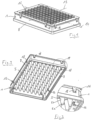
- a microplate 1 comprises a rectangular first plate 2 and a circumferential side wall 4 with four sides 4.1 to 4.4 which projects downward from the outer edge 3 of the first plate 2.
- the first plate 2 and the side wall 4 are also referred to as the “frame”.
- 96 vessels 5 are arranged in eight rows and twelve columns, which are connected to the top of the first plate 2, protrude downwards from the underside of the first plate 2 and have an opening 6 at the top of the first plate 2.
- Each opening 6 is surrounded by a small border 7 which protrudes upward from the top of the first plate 2.
- the vessels 5 have a shape that tapers downwards. They have a conical vessel section 5.1 connected at the top to the first plate 2 diameter decreasing at the bottom and a first downwardly curved, spherical shell-shaped vessel base 5.2.
- the side wall 4 has an outwardly projecting flange 8 at the lower edge. In the vertical section, this has an inverted L-profile and forms an outwardly and downwardly projecting extension 9 of the side wall 4.
- the microplate 1 has 2 snap openings 10 on the edge of the first plate.
- Each snap opening 10 is arranged in part 10.1 in the lateral edge region of the first plate 2 and in another part 10.2 in the upper edge region of the side wall 4.
- the part 10.1 of the snap opening 10, which is formed in the lateral edge region of the first plate 2 has an upper boundary surface 11.1 running parallel to the outer edge of the first plate. From the lateral ends of each upper boundary surface 11.1, upper lateral boundary surfaces 11.2, 11.3 extend perpendicularly thereto to the outer edge of the first plate 2.
- the further part 10.2 of the snap openings 10, which is arranged in the upper edge region of the side wall 4, has a lower boundary surface 12.1 running parallel to the upper edge of the side wall 4. From the outer ends of each lower boundary surface 12.1, lower lateral boundary surfaces 12.2, 12.3 of the further part 10.2 of the snap openings 10 extend vertically upwards to the upper edge of the side wall 4.
- the upper boundary surface 11.1 is aligned with an inside 13 of the side wall 4, which adjoins the lower boundary surface 12.1, or is offset inwards with respect to this inside 13.
- two snap openings 10 are each arranged near a corner of the side wall 4.
- the snap openings 10 are arranged symmetrically with respect to a longitudinal central axis 14 of the first plate 2.
- two snap openings 10 are each arranged near a corner of the side wall 4.
- the snap openings 10 are arranged symmetrically with respect to a transverse central axis 15 of the first plate 2.
- the microplate 1 is made of one or more plastics, with the first plate 2 and the side wall 4 optionally made of a different plastic than the vessels 5.
- the microplate is made entirely of polystyrene, polycarbonate or polypropylene, or the first plate 2 and side wall 4 are made of polycarbonate and the vessels 5 are made of polypropylene, silicone or liquid silicone rubber.
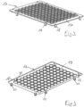
- a lid 16 is arranged on the microplate 1, which is in the Figs. 4 and 5 is shown.
- the lid 16 has a rectangular second plate 17, which is designed to be congruent with the first plate 2.
- the lid 16 has snap hooks 18 which protrude downwards from the upper outer edge 19 of the second plate 17.
- Each snap hook 18 has a vertical web 20 which is connected at the upper end to the upper outer edge 19 of the second plate 17. Furthermore, each snap hook 18 at the lower end of the vertical web 20 has a horizontal web 21 which projects inwards, ie below the second plate 17. The Horizontal web 21 has a first sliding surface 22 inclined to the vertical at the outer end on the underside.
- the lid 16 has two snap hooks 18 on each of the two long sides of the second plate 17, each snap hook 18 being arranged at a corner of the second plate 17.
- the two snap hooks 18 on the two long sides of the second plate 17 are arranged symmetrically with respect to a longitudinal central axis 14 of the second plate 17.
- the lid 16 also has two snap hooks 18 on each of the two short sides of the second plate 17, each of which is arranged near a corner of the second plate 17.
- the snap hooks 18 on the two shorter sides are arranged symmetrically with respect to a transverse central axis 15 of the second plate 17.
- the first sliding surfaces 22 are each arranged on mutually facing inner sides of the snap hooks 18 and the same first sliding surfaces 22 are inclined upwards towards one another.
- the first sliding surfaces 22 on the mutually facing inner sides of the snap hooks 18 form an acute angle with one another, the apex of which is arranged above the second plate 17.
- the second plate 17 has a recess 23 above the horizontal web 22 of each snap hook 18. This makes it easier to remove the cover 16 from a mold during injection molding.
- each sealing element 24 is dome-shaped (spherical shell-shaped) and held in a circular hole 25 in the second plate 17.
- each sealing element 24 has an outwardly projecting, circumferential upper flange 26 at the upper edge and below and at a distance therefrom an outwardly projecting, circumferential lower flange 27. Between the upper flange 26 and the lower flange 27 of each sealing element 24, the edge engages a hole 25 in the second plate 17, whereby the sealing element 24 is held on the second plate 17.
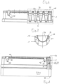
- each sealing element 17 is designed in such a way that each sealing element 17 can be partially inserted into a vessel 5 of the microplate 1, the sealing element 17 resting sealingly on its inside at the upper edge of the vessel 5, as in 6 and 7 shown.
- the lid 16 is made by injection molding.
- the exemplary embodiment with the sealing elements 24 is manufactured using a multi-component injection molding process, in which the second plate 17 can be injected in a first step and the sealing elements 24 can be injection-molded onto the second plate 17 in a second step.
- the second plate 17 is made, for example, from polystyrene, polycarbonate or polypropylene and the sealing elements 24 from polypropylene, silicone or liquid silicone rubber.
- an unlocking device 28 has a rectangular frame 29, which comprises four frame strips 29.1 to 29.4, which are connected to one another at corners of the frame 29.
- the lower edge of the frame 29 has a horizontal, flat bearing surface 30 for placing the frame 29 on a horizontal surface.
- the frame has a horizontal, flat support surface 21 for placing a microplate 1.
- the frame strips each have a flat inner surface 32.
- the frame 29 has a paragraph 33 running approximately halfway up.
- the frame strips 29.1 to 29.4 each have a flat outer surface 34.1, 34.2.
- the frame 29 has two vertical grooves 35.1, 35.2 on the narrow frame strips 29.1, 29.2 on the outside above the shoulder, each vertical groove 35.1, 35.2 being arranged next to a corner of the frame 29.
- the frame 29 encloses a receptacle 36, which is delimited by the insides of the frame strips 29.1 to 29.4.
- the frame 29 has a circumferential chamfer 37 on the outside on the upper edge, which forms second sliding surfaces 38.
- the second sliding surfaces 38 form an angle to the vertical.
- the second sliding surfaces 38 are arranged on opposite frame strips 29.1 to 29.3 in such a way that they are inclined upwards toward one another. As a result, they form an acute angle with one another with an apex above the frame 29.
- the frame strips 29.1 to 29.4 form supporting projections 39.1 to 39.4 for placing the microplate 1.
- the lid 16 can be placed on the microplate 1, with the snap hooks 18 forming snap connections on the snap openings 10 in which the horizontal webs 22 reach under the first plate 2 at the side edges.
- the sealing elements 24 engage sealingly in the openings 6 of the vessels 5, as in the 6 and 7 shown. In this position, the lid 16 is secured to the microplate 1 by the snap hooks 18.
- the lid 16 is placed on the microplate 1 from above.
- the snap hooks 18 on the lid 16 dip into the snap openings 10 of the microplate 1.
- the snap hooks 18 snap in a form-fitting manner behind the edges of the snap openings 10 and hold the lid 16 on the microplate 1.
- the sealing elements 24 lie sealingly in the upper region on the inside of the vessels 5 and cover them.
- the cover 16 can be removed again by placing the microplate 1 with the snapped-on cover 16 onto the unlocking device 28.
- the outside and top of the unlocking device 28 is designed to be negative to the inside of the microplate 1.
- the microplate 1 can be placed on the frame 29 with a lid 16 snapped onto it, so that the frame 29 engages from below into the circumferential side wall 4 of the microplate and the vessels 5 are immersed in the receptacle 36.
- vertical ribs can engage in the grooves 35.1, 35.2 of the frame 29 on the inside of the side wall 4 for structural stiffening.
- the first sliding surfaces 22 of the snap hooks 18 slide off onto the second sliding surfaces 38 of the frame 29 and the snap hooks 18 are thereby bent outwards. This releases the snap connections so that the cover 16 is lifted off the microplate 1 and removed can be. This is in the Fig. 12 shown. The cover 16 can be pushed upwards by the frame 29. After the snap connections have been released, the cover 16 can be removed from the microplate 1.
- the placement and snapping of the lid 16 onto the microplate 1 as well as the loosening of the snap connections and removal of the lid 16 from the microplate 1 can be carried out automatically, for example in a laboratory machine or automatic dosing machine.
- the microplate and the lid 16 can be handled by grippers of an automated system (e.g. Applicant's Epmotion).
- an automated system e.g. Applicant's Epmotion
- the lid 16 like the microplate 1, can be dimensionally stable and easy to handle due to the plastic used and, if necessary, through structural stiffening (ribbing or frame).
- the sealing elements 24 are preferably formed from a correspondingly soft or elastic material. This is, for example, a thermoplastic material, e.g. a soft PP, PE or TPE. Due to the flexibility of the sealing elements 24 and their arrangement in the grid of the vessels 5 of the microplate 1, each sealing element 24 can cover a vessel 5.
- a thermoplastic material e.g. a soft PP, PE or TPE. Due to the flexibility of the sealing elements 24 and their arrangement in the grid of the vessels 5 of the microplate 1, each sealing element 24 can cover a vessel 5.
- the cover 16 with the sealing elements 24 can consist of several assembled parts or can be produced using two-component injection molding.
Landscapes
- Health & Medical Sciences (AREA)
- Chemical & Material Sciences (AREA)
- Zoology (AREA)
- Life Sciences & Earth Sciences (AREA)
- Engineering & Computer Science (AREA)
- Bioinformatics & Cheminformatics (AREA)
- Organic Chemistry (AREA)
- Wood Science & Technology (AREA)
- Clinical Laboratory Science (AREA)
- General Health & Medical Sciences (AREA)
- Biomedical Technology (AREA)
- Sustainable Development (AREA)
- Biochemistry (AREA)
- General Engineering & Computer Science (AREA)
- Microbiology (AREA)
- Genetics & Genomics (AREA)
- Biotechnology (AREA)
- Analytical Chemistry (AREA)
- Hematology (AREA)
- Chemical Kinetics & Catalysis (AREA)
- Closures For Containers (AREA)
Priority Applications (5)
| Application Number | Priority Date | Filing Date | Title |
|---|---|---|---|
| EP22193653.7A EP4331723B1 (fr) | 2022-09-02 | 2022-09-02 | Ensemble comprenant une microplaque, un couvercle et un dispositif de libération d'une liaison encliquetable entre la microplaque et le couvercle |
| CN202380062468.0A CN119816371A (zh) | 2022-09-02 | 2023-08-15 | 包括微孔板、盖子的套件和用于解除微孔板和盖子之间的卡扣连接的装置 |
| PCT/EP2023/072444 WO2024046752A1 (fr) | 2022-09-02 | 2023-08-15 | Ensemble comprenant une microplaque, un couvercle et un dispositif de libération d'une liaison par encliquetage entre la microplaque et le couvercle |
| KR1020257006986A KR20250042833A (ko) | 2022-09-02 | 2023-08-15 | 마이크로플레이트, 뚜껑, 및 마이크로플레이트와 뚜껑 사이의 스냅 연결을 해제하기 위한 장치를 포함하는 세트 |
| DE112023003679.9T DE112023003679A5 (de) | 2022-09-02 | 2023-08-15 | Set umfassend eine mikroplatte, einen deckel und eine vorrichtung zum lösen einer schnappverbindung zwischen mikroplatte und deckel |
Applications Claiming Priority (1)
| Application Number | Priority Date | Filing Date | Title |
|---|---|---|---|
| EP22193653.7A EP4331723B1 (fr) | 2022-09-02 | 2022-09-02 | Ensemble comprenant une microplaque, un couvercle et un dispositif de libération d'une liaison encliquetable entre la microplaque et le couvercle |
Publications (3)
| Publication Number | Publication Date |
|---|---|
| EP4331723A1 true EP4331723A1 (fr) | 2024-03-06 |
| EP4331723C0 EP4331723C0 (fr) | 2025-06-18 |
| EP4331723B1 EP4331723B1 (fr) | 2025-06-18 |
Family
ID=83191903
Family Applications (1)
| Application Number | Title | Priority Date | Filing Date |
|---|---|---|---|
| EP22193653.7A Active EP4331723B1 (fr) | 2022-09-02 | 2022-09-02 | Ensemble comprenant une microplaque, un couvercle et un dispositif de libération d'une liaison encliquetable entre la microplaque et le couvercle |
Country Status (5)
| Country | Link |
|---|---|
| EP (1) | EP4331723B1 (fr) |
| KR (1) | KR20250042833A (fr) |
| CN (1) | CN119816371A (fr) |
| DE (1) | DE112023003679A5 (fr) |
| WO (1) | WO2024046752A1 (fr) |
Cited By (1)
| Publication number | Priority date | Publication date | Assignee | Title |
|---|---|---|---|---|
| WO2026017533A1 (fr) | 2024-07-16 | 2026-01-22 | Martin Gajewski | Cuve de réaction et agencement de réaction |
Citations (3)
| Publication number | Priority date | Publication date | Assignee | Title |
|---|---|---|---|---|
| US20030180191A1 (en) * | 2000-09-18 | 2003-09-25 | Hideyuki Suzuki | Micro well array and method of sealing liquid using the micro well array |
| DE10066431B4 (de) | 2000-06-08 | 2013-10-24 | Eppendorf Ag | Mikrotiterplatte |
| US20210299655A1 (en) * | 2018-08-03 | 2021-09-30 | Randox Laboratories Ltd | Pcr cartridge |
-
2022
- 2022-09-02 EP EP22193653.7A patent/EP4331723B1/fr active Active
-
2023
- 2023-08-15 WO PCT/EP2023/072444 patent/WO2024046752A1/fr not_active Ceased
- 2023-08-15 CN CN202380062468.0A patent/CN119816371A/zh active Pending
- 2023-08-15 KR KR1020257006986A patent/KR20250042833A/ko active Pending
- 2023-08-15 DE DE112023003679.9T patent/DE112023003679A5/de active Pending
Patent Citations (3)
| Publication number | Priority date | Publication date | Assignee | Title |
|---|---|---|---|---|
| DE10066431B4 (de) | 2000-06-08 | 2013-10-24 | Eppendorf Ag | Mikrotiterplatte |
| US20030180191A1 (en) * | 2000-09-18 | 2003-09-25 | Hideyuki Suzuki | Micro well array and method of sealing liquid using the micro well array |
| US20210299655A1 (en) * | 2018-08-03 | 2021-09-30 | Randox Laboratories Ltd | Pcr cartridge |
Cited By (1)
| Publication number | Priority date | Publication date | Assignee | Title |
|---|---|---|---|---|
| WO2026017533A1 (fr) | 2024-07-16 | 2026-01-22 | Martin Gajewski | Cuve de réaction et agencement de réaction |
Also Published As
| Publication number | Publication date |
|---|---|
| WO2024046752A1 (fr) | 2024-03-07 |
| DE112023003679A5 (de) | 2025-07-10 |
| CN119816371A (zh) | 2025-04-11 |
| KR20250042833A (ko) | 2025-03-27 |
| EP4331723C0 (fr) | 2025-06-18 |
| EP4331723B1 (fr) | 2025-06-18 |
Similar Documents
| Publication | Publication Date | Title |
|---|---|---|
| DE3137234C2 (de) | Schale für eine Gruppe von Gewebekulturen | |
| DE69021672T2 (de) | Küvetten-Matrix und sein Tablett. | |
| DE69322778T2 (de) | Vakuumplatte | |
| EP2789389B1 (fr) | Dispositif pour stockage et pour fournir des embouts de pipette | |
| EP3576518B1 (fr) | Plateau de culture de plantes, système comportant plateau et godet | |
| EP3342485B1 (fr) | Supports d'éléments de réactifs | |
| EP1161994B2 (fr) | Plaque de microtitrage | |
| DE69902235T2 (de) | Verschlusskappen-array mit blindbohrungen | |
| EP4190452B1 (fr) | Espaceur permettant de maintenir les porte-pipettes empilés à distance les uns des autres | |
| EP4331723B1 (fr) | Ensemble comprenant une microplaque, un couvercle et un dispositif de libération d'une liaison encliquetable entre la microplaque et le couvercle | |
| EP3302806A1 (fr) | Emballage d'embouts de pipette | |
| EP1682274A1 (fr) | Plate-forme | |
| DE202020100361U1 (de) | Variable Transportpalette für Pflanzentöpfe | |
| DE3037892C2 (de) | Stapel- und wendbare Blockform zur Käseherstellung | |
| DE602004011926T2 (de) | Mikroplatte und Deckel zur robotischen Handhabung | |
| EP1417032B1 (fr) | Procede de fabrication d'une couverture de fermeture et couverture de fermeture ainsi fabriquee | |
| EP0671467A2 (fr) | Disque de petri ajustable | |
| DE10038386C2 (de) | Kunststoffbehälter sowie Verfahren und Vorrichtung zu seiner Herstellung | |
| DE202020004181U1 (de) | Set aus einer Anzuchtplatte für Pflanzen und einer Trägerplatte | |
| EP1031276B1 (fr) | Appareil pour la culture de chicorée | |
| DE202020000321U1 (de) | Pflanzenzuchtbehältnis für die In-Vitro-Vermehrung | |
| DE102024133958B3 (de) | Dialysemaschine mit einer lösbaren, wendbaren Auflageplatte, Auflageplatte, Verwendung einer Auflageplatte in einer Dialysemaschine und System aus einer Dialysemaschine und einem Fluidbehälter | |
| DE29923461U1 (de) | Mikroplattenanordnung und Verschluß | |
| DE10028536B4 (de) | Mikrotiterplatte | |
| DE202023106191U1 (de) | Pflanzenanzuchtbehältnis für In-Vitro-Pflanzenkultivierung |
Legal Events
| Date | Code | Title | Description |
|---|---|---|---|
| PUAI | Public reference made under article 153(3) epc to a published international application that has entered the european phase |
Free format text: ORIGINAL CODE: 0009012 |
|
| STAA | Information on the status of an ep patent application or granted ep patent |
Free format text: STATUS: THE APPLICATION HAS BEEN PUBLISHED |
|
| AK | Designated contracting states |
Kind code of ref document: A1 Designated state(s): AL AT BE BG CH CY CZ DE DK EE ES FI FR GB GR HR HU IE IS IT LI LT LU LV MC MK MT NL NO PL PT RO RS SE SI SK SM TR |
|
| STAA | Information on the status of an ep patent application or granted ep patent |
Free format text: STATUS: REQUEST FOR EXAMINATION WAS MADE |
|
| 17P | Request for examination filed |
Effective date: 20240902 |
|
| RBV | Designated contracting states (corrected) |
Designated state(s): AL AT BE BG CH CY CZ DE DK EE ES FI FR GB GR HR HU IE IS IT LI LT LU LV MC MK MT NL NO PL PT RO RS SE SI SK SM TR |
|
| GRAP | Despatch of communication of intention to grant a patent |
Free format text: ORIGINAL CODE: EPIDOSNIGR1 |
|
| STAA | Information on the status of an ep patent application or granted ep patent |
Free format text: STATUS: GRANT OF PATENT IS INTENDED |
|
| RIC1 | Information provided on ipc code assigned before grant |
Ipc: C12M 1/00 20060101ALI20250130BHEP Ipc: B29C 65/58 20060101ALI20250130BHEP Ipc: C12M 1/32 20060101ALI20250130BHEP Ipc: B01L 3/00 20060101AFI20250130BHEP |
|
| INTG | Intention to grant announced |
Effective date: 20250217 |
|
| GRAS | Grant fee paid |
Free format text: ORIGINAL CODE: EPIDOSNIGR3 |
|
| GRAA | (expected) grant |
Free format text: ORIGINAL CODE: 0009210 |
|
| STAA | Information on the status of an ep patent application or granted ep patent |
Free format text: STATUS: THE PATENT HAS BEEN GRANTED |
|
| AK | Designated contracting states |
Kind code of ref document: B1 Designated state(s): AL AT BE BG CH CY CZ DE DK EE ES FI FR GB GR HR HU IE IS IT LI LT LU LV MC MK MT NL NO PL PT RO RS SE SI SK SM TR |
|
| REG | Reference to a national code |
Ref country code: GB Ref legal event code: FG4D Free format text: NOT ENGLISH |
|
| REG | Reference to a national code |
Ref country code: CH Ref legal event code: EP |
|
| REG | Reference to a national code |
Ref country code: DE Ref legal event code: R096 Ref document number: 502022004303 Country of ref document: DE |
|
| REG | Reference to a national code |
Ref country code: CH Ref legal event code: EP |
|
| REG | Reference to a national code |
Ref country code: IE Ref legal event code: FG4D Free format text: LANGUAGE OF EP DOCUMENT: GERMAN |
|
| U01 | Request for unitary effect filed |
Effective date: 20250618 |
|
| U07 | Unitary effect registered |
Designated state(s): AT BE BG DE DK EE FI FR IT LT LU LV MT NL PT RO SE SI Effective date: 20250626 |
|
| REG | Reference to a national code |
Ref country code: CH Ref legal event code: U11 Free format text: ST27 STATUS EVENT CODE: U-0-0-U10-U11 (AS PROVIDED BY THE NATIONAL OFFICE) Effective date: 20251001 |
|
| PG25 | Lapsed in a contracting state [announced via postgrant information from national office to epo] |
Ref country code: GR Free format text: LAPSE BECAUSE OF FAILURE TO SUBMIT A TRANSLATION OF THE DESCRIPTION OR TO PAY THE FEE WITHIN THE PRESCRIBED TIME-LIMIT Effective date: 20250919 Ref country code: NO Free format text: LAPSE BECAUSE OF FAILURE TO SUBMIT A TRANSLATION OF THE DESCRIPTION OR TO PAY THE FEE WITHIN THE PRESCRIBED TIME-LIMIT Effective date: 20250918 |
|
| PG25 | Lapsed in a contracting state [announced via postgrant information from national office to epo] |
Ref country code: HR Free format text: LAPSE BECAUSE OF FAILURE TO SUBMIT A TRANSLATION OF THE DESCRIPTION OR TO PAY THE FEE WITHIN THE PRESCRIBED TIME-LIMIT Effective date: 20250618 |
|
| PG25 | Lapsed in a contracting state [announced via postgrant information from national office to epo] |
Ref country code: RS Free format text: LAPSE BECAUSE OF FAILURE TO SUBMIT A TRANSLATION OF THE DESCRIPTION OR TO PAY THE FEE WITHIN THE PRESCRIBED TIME-LIMIT Effective date: 20250918 |
|
| U20 | Renewal fee for the european patent with unitary effect paid |
Year of fee payment: 4 Effective date: 20250924 |
|
| PG25 | Lapsed in a contracting state [announced via postgrant information from national office to epo] |
Ref country code: IS Free format text: LAPSE BECAUSE OF FAILURE TO SUBMIT A TRANSLATION OF THE DESCRIPTION OR TO PAY THE FEE WITHIN THE PRESCRIBED TIME-LIMIT Effective date: 20251018 |
|
| PG25 | Lapsed in a contracting state [announced via postgrant information from national office to epo] |
Ref country code: SM Free format text: LAPSE BECAUSE OF FAILURE TO SUBMIT A TRANSLATION OF THE DESCRIPTION OR TO PAY THE FEE WITHIN THE PRESCRIBED TIME-LIMIT Effective date: 20250618 |
|
| PGFP | Annual fee paid to national office [announced via postgrant information from national office to epo] |
Ref country code: CH Payment date: 20251001 Year of fee payment: 4 |
|
| PG25 | Lapsed in a contracting state [announced via postgrant information from national office to epo] |
Ref country code: CZ Free format text: LAPSE BECAUSE OF FAILURE TO SUBMIT A TRANSLATION OF THE DESCRIPTION OR TO PAY THE FEE WITHIN THE PRESCRIBED TIME-LIMIT Effective date: 20250618 |
|
| PG25 | Lapsed in a contracting state [announced via postgrant information from national office to epo] |
Ref country code: PL Free format text: LAPSE BECAUSE OF FAILURE TO SUBMIT A TRANSLATION OF THE DESCRIPTION OR TO PAY THE FEE WITHIN THE PRESCRIBED TIME-LIMIT Effective date: 20250618 |
|
| PG25 | Lapsed in a contracting state [announced via postgrant information from national office to epo] |
Ref country code: SK Free format text: LAPSE BECAUSE OF FAILURE TO SUBMIT A TRANSLATION OF THE DESCRIPTION OR TO PAY THE FEE WITHIN THE PRESCRIBED TIME-LIMIT Effective date: 20250618 |
|
| PG25 | Lapsed in a contracting state [announced via postgrant information from national office to epo] |
Ref country code: ES Free format text: LAPSE BECAUSE OF FAILURE TO SUBMIT A TRANSLATION OF THE DESCRIPTION OR TO PAY THE FEE WITHIN THE PRESCRIBED TIME-LIMIT Effective date: 20250618 |
|
| PLBE | No opposition filed within time limit |
Free format text: ORIGINAL CODE: 0009261 |
|
| STAA | Information on the status of an ep patent application or granted ep patent |
Free format text: STATUS: NO OPPOSITION FILED WITHIN TIME LIMIT |
|
| REG | Reference to a national code |
Ref country code: CH Ref legal event code: L10 Free format text: ST27 STATUS EVENT CODE: U-0-0-L10-L00 (AS PROVIDED BY THE NATIONAL OFFICE) Effective date: 20260430 |