EP4190452B1 - Espaceur permettant de maintenir les porte-pipettes empilés à distance les uns des autres - Google Patents
Espaceur permettant de maintenir les porte-pipettes empilés à distance les uns des autres Download PDFInfo
- Publication number
- EP4190452B1 EP4190452B1 EP21211549.7A EP21211549A EP4190452B1 EP 4190452 B1 EP4190452 B1 EP 4190452B1 EP 21211549 A EP21211549 A EP 21211549A EP 4190452 B1 EP4190452 B1 EP 4190452B1
- Authority
- EP
- European Patent Office
- Prior art keywords
- spacer
- pipette tip
- corners
- lateral wall
- spacer according
- Prior art date
- Legal status (The legal status is an assumption and is not a legal conclusion. Google has not performed a legal analysis and makes no representation as to the accuracy of the status listed.)
- Active
Links
Images




Classifications
-
- B—PERFORMING OPERATIONS; TRANSPORTING
- B01—PHYSICAL OR CHEMICAL PROCESSES OR APPARATUS IN GENERAL
- B01L—CHEMICAL OR PHYSICAL LABORATORY APPARATUS FOR GENERAL USE
- B01L9/00—Supporting devices; Holding devices
- B01L9/54—Supports specially adapted for pipettes and burettes
- B01L9/543—Supports specially adapted for pipettes and burettes for disposable pipette tips, e.g. racks or cassettes
-
- B—PERFORMING OPERATIONS; TRANSPORTING
- B01—PHYSICAL OR CHEMICAL PROCESSES OR APPARATUS IN GENERAL
- B01L—CHEMICAL OR PHYSICAL LABORATORY APPARATUS FOR GENERAL USE
- B01L9/00—Supporting devices; Holding devices
- B01L9/52—Supports specially adapted for flat sample carriers, e.g. for plates, slides, chips
- B01L9/527—Supports specially adapted for flat sample carriers, e.g. for plates, slides, chips for microfluidic devices, e.g. used for lab-on-a-chip
-
- B—PERFORMING OPERATIONS; TRANSPORTING
- B01—PHYSICAL OR CHEMICAL PROCESSES OR APPARATUS IN GENERAL
- B01L—CHEMICAL OR PHYSICAL LABORATORY APPARATUS FOR GENERAL USE
- B01L2200/00—Solutions for specific problems relating to chemical or physical laboratory apparatus
- B01L2200/02—Adapting objects or devices to another
- B01L2200/025—Align devices or objects to ensure defined positions relative to each other
-
- B—PERFORMING OPERATIONS; TRANSPORTING
- B01—PHYSICAL OR CHEMICAL PROCESSES OR APPARATUS IN GENERAL
- B01L—CHEMICAL OR PHYSICAL LABORATORY APPARATUS FOR GENERAL USE
- B01L2300/00—Additional constructional details
- B01L2300/12—Specific details about materials
- B01L2300/123—Flexible; Elastomeric
-
- B—PERFORMING OPERATIONS; TRANSPORTING
- B01—PHYSICAL OR CHEMICAL PROCESSES OR APPARATUS IN GENERAL
- B01L—CHEMICAL OR PHYSICAL LABORATORY APPARATUS FOR GENERAL USE
- B01L3/00—Containers or dishes for laboratory use, e.g. laboratory glassware; Droppers
- B01L3/02—Burettes; Pipettes
- B01L3/0275—Interchangeable or disposable dispensing tips
Definitions
- the invention relates to a spacer for holding stacked plate-shaped and substantially rectangular pipette tip carriers with holes and pipette tips inserted therein at a distance from one another.
- Pipette tips are used in particular in biological, chemical, biochemical, medical or forensic laboratories to dispense small amounts of liquid using pipetting devices.
- Pipetting devices are hand pipettes, automatic dispensing stations or laboratory machines (workstations).
- Pipetting devices have one or more channels to accommodate a single pipette tip or a large number of pipette tips in a row or in a matrix arrangement.
- pipetting devices have attachments or blind holes onto or into which the pipette tips can be clamped with their upper ends.
- the distances between the channels are usually coordinated with the distances between the wells of standardized microplates in accordance with ANSI SBS 1 to 4; American National Standard; American National Standard Institute, 2006.
- plastic pipette tips are used for single use ( disposables ). These must be made available in large quantities for carrying out tests.
- pipette tips plate-shaped and essentially rectangular pipette tip carriers with a large number of holes in a matrix arrangement are used.
- the pipette tips are inserted into the holes from above, but do not fall through due to a diameter that widens towards the top or a collar.
- the pipette tip carrier is placed on the edge of an upper opening of a frame or box so that the Pipette tips fit into the upper opening.
- the pipette tips can be removed from the pipette tip holder by pressing them onto the attachments or into the blind holes.
- the pipette tips are ejected from the pipetting device into a container for disposal using an ejector device.
- the EP 2 848 308 B1 describes a spacer that includes centering spring elements arranged on the inside of the long sides and short sides of the side wall, each of which includes a resilient part that is spaced from the inside of the side wall to which the centering spring element is attached.
- the resilient part can exert a spring effect between the inside of the respective side wall and a part of a pipette tip carrier to be stacked that is received in a central opening of the spacer.
- the centering spring elements are designed in such a way that they act on a pipette tip carrier on which the spacer rests and minimize the horizontal play between the pipette tip carrier and the spacer without locking the pipette tip carrier to the spacer.
- the invention is based on the object of providing a spacer for plate-shaped pipette tip carriers stacked on top of each other, which enables improved centering and stabilization of a carrier stack with reduced material usage and manufacturing effort.
- the spacer according to the invention for holding plate-shaped and essentially rectangular pipette tip carriers stacked on top of one another at a distance from one another comprises a circumferential side wall which forms an essentially rectangular frame with two longitudinal and two transverse sides, which has a horizontal base on a lower edge for supporting a pipette tip carrier on the top side, a horizontal support surface on an upper edge for supporting a further pipette tip carrier on the underside, pins projecting vertically upwards from the upper edge at corners between adjacent longitudinal and transverse sides, and bending elements on the side wall, wherein the bending elements are bendable in a direction running at an acute angle to the adjacent longitudinal and transverse sides.
- the bending elements at the corners of the side wall which can be bent in a direction running at an acute angle to the adjacent longitudinal and transverse sides, center the spacer in the stack.
- the bending elements can be bent or deflected by contours of a further spacer and/or a pipette tip carrier supported on the support surface of the introduced further spacer, or they rest against it without play, introduced from below into the peripheral side wall.
- the bending element can be bent outwards or inwards with respect to the frame of the spacer.
- a slight bending or deflection or play-free contact of the bending elements achieves centering of the spacer on the contours of the further spacer and/or a pipette tip carrier supported on the further spacer, introduced from below.
- the forces acting due to the centering between the bending elements and the contours of the spacer or pipette tip carrier can be kept so low that the spacer can be separated from the other spacer and the the pipette tip carrier supported on it can be pulled off without the other spacer or the pipette tip carrier being taken along with it.
- This can be achieved in particular by a particularly flexible design of the bending elements and/or by precise or low-tolerance manufacturing of the bending elements and the contours of the spacer and/or the pipette tip carrier.
- the spacer can be manufactured using less material because the bending elements only have to be present at the corners of the spacer, with formation at just two diametrically opposite corners being sufficient. Furthermore, the bending elements can be formed within the circumferential side wall and no additional spring elements are required on the inside of the side wall. This also makes it possible to reduce the cost of tools for injection molding the spacer and the cost of manufacturing the spacer overall. If the centering is achieved by placing the bending elements on the contours of another spacer of the same design, it may be sufficient to manufacture the spacer with the relevant contours and bending elements with a correspondingly low tolerance, and the pipette tip carrier with larger tolerances, which further reduces the effort required for production.
- the bending elements can be bent by means of pins of an identically constructed additional spacer inserted from below and/or by means of corners or radii at the corners between adjacent longitudinal and transverse sides of a pipette tip carrier supported on the support surface of the additional spacer.
- the pins of the additional spacer and/or the corners or radii at the corners of the pipette tip carrier supporting the additional spacer form the contours by means of which the bending elements can be bent or deflected or against which the bending elements rest without being bent or deflected.
- the pins of the additional spacer and/or corners or Radii of a pipette tip carrier supported on it are arranged at the corners of the spacer placed on it, so that they are particularly suitable for centering the spacer.
- the pipette tip carrier used to center the spacer has a rectangular plate-shaped base body, holes extending vertically from the top to the bottom of the base body for receiving pipette tips, an edge surrounding the base body with an upper contact surface arranged lower than the top of the base body for placing a spacer with a standing surface on the lower edge and a lower contact surface on the downward-facing side for placing on a support surface on the upper edge of another spacer and corners of the plate-shaped base body above the surrounding edge.
- the corners of the plate-shaped base body preferably have radii.
- the pins are cylindrical and/or have a conical or spherical end. This makes it easier to place the spacer on another spacer while the bending elements rest on the pins.
- the direction in which the bending elements can be bent is aligned diagonally to the corners of the frame. Accordingly, this direction extends along a straight line that connects two non-adjacent corners of the rectangular frame.
- the direction in which the bending elements can be bent can be aligned at different or equal acute angles to the adjacent longitudinal and transverse sides.
- the spacer has the bending elements at at least two diametrically opposite corners, preferably at all four corners. Centering that prevents displacement in the direction of the longitudinal and transverse sides of the spacer can already be achieved by bending elements that are arranged only at two diametrically opposite corners. Bending elements are preferably arranged at all four corners in order to form particularly stable stacks.
- the circumferential side wall is connected at the top to an inwardly projecting circumferential flange, which has a support surface on its upper side for supporting another pipette tip carrier.
- the circumferential flange increases the stability of the spacer.
- the pins project upwards from the upper side of the flange.
- the bending elements have vertical cylinder shells at the corners at a distance from the side wall, which are connected to the spacer at their upper ends.
- the cylinder shells can be designed in such a way that they are supported on the radii of a pipette tip carrier, which is supported on another spacer that is inserted into the circumferential side wall with the pins, in order to achieve centering.
- the cylinder shells rest with concavely curved inner sides on the radii of the pipette tip carrier. In order to bend the cylinder shells slightly in the radial direction to the pins, they are only attached to the spacer at the upper ends.
- the cylinder shells are connected to the spacer in one piece.
- the bending elements each have at least one vertical slot at a corner of the side wall, starting from the lower edge of the side wall and ending above the lower edge in the side wall.
- the slots form bending elements in the side wall.
- the slots enable the adjacent areas of the side wall to be easily bent radially outwards by means of pins inserted from below.
- the vertical slots at the corners extend from the inside to the outside of the side wall. This results in particularly flexible bending elements.
- the vertical slots do not extend from the inside to the outside, which results in somewhat stiffer bending elements.
- the slots extend from the inside to just before the outside of the side wall or from the outside to just before the inside of the side wall.
- the areas of the side wall at the corners between two adjacent vertical slots are particularly flexible and can be placed against the inserted pins, further reducing the force.
- the two vertical slots are arranged symmetrically with respect to the respective corner. This ensures that the force is applied evenly at the corners.
- only one vertical slot is arranged at each corner.
- horizontal slots are arranged at the corners in the side wall, each of which extends from the corner into the two adjacent areas of the side wall, and the vertical slots open at the top into the horizontal slot at the same corner.
- horizontal slots the bending softness of the bending elements formed by the vertical slots is further increased and the forces between stacked spacers are further reduced.
- the side wall has an inner radius on the inside at the corners and/or an outer radius on the outside.
- the radius further increases the flexural flexibility of the bending elements.
- the radius on the inside of the side wall makes it easier to insert the pins of another spacer into the surrounding side wall of the spacer.
- the side wall has a radius on the inside at the corners that matches or exceeds the radius of the pins.
- the invention further relates to a transport unit for pipette tips comprising a pipette tip box, a pipette tip carrier provided with pipette tips and placed on the pipette tip box, and at least one arrangement placed on the pipette tip carrier comprising a spacer according to one of claims 1 to 15 or one of the preceding embodiments and a further pipette tip carrier placed on the spacer and provided with pipette tips.
- the transport unit is formed by placing one or more arrangements of a spacer with a pipette tip carrier placed thereon, which is provided with pipette tips, on a pipette tip box and a pipette tip carrier placed thereon, which is provided with pipette tips.
- the pipette tips in pipette tip carriers arranged one above the other are kept at a distance from one another by the at least one spacer, so that they can engage with one another without clamping against one another. In this way, a space-saving and compact transport unit is achieved.
- the transport unit can also be used to store the pipette tips.
- a lid is placed on a pipette tip carrier or on a spacer placed on a pipette tip carrier.
- the lid covers the transport unit at the top and protects it from contamination. If the lid is placed on a pipette tip carrier and protrudes slightly above the pipette tips inserted in it, the lid can be designed like a hood or have recesses on the underside to accommodate the protruding parts of the pipette tips. If the lid is placed on a spacer, it can be designed like a plate or like a hood.
- the subject matter of the invention is the use of a spacer according to one of claims 1 to 15 or one of the preceding embodiments for forming a stack of pipette tip carriers which are kept at a distance from one another by means of spacers and are provided with pipette tips.
- vertical and horizontal as well as “top” and “bottom” and derived terms such as “above” and “below” refer to a spacer which is placed with its base at the lower edge on a horizontal substrate.
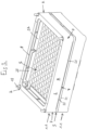
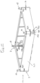
- a spacer 1.1 has a circumferential side wall 2 which forms a substantially vertical frame 3 with two longitudinal and two transverse sides. At the lower edge, the spacer has a horizontal base 4 for support on an upper side of a pipette tip carrier 5.
- the horizontal base 4 comprises a shoulder 6.1 at each corner 7 and three shoulders 6.2 on each longitudinal side of the frame.
- the spacer 1.1 has an inwardly projecting circumferential flange 8.
- the upper side of the flange 8 is a horizontal support surface 9 for supporting another pipette tip carrier 5 on the underside.
- each pin 10 projects upwards from the circumferential flange 8.
- Each pin 10 is arranged in a recess 11 on the upper side of the flange 8 and has a conical base 12 at the lower end which is arranged within the recess 11. Furthermore, each pin 10 tapers towards the upper end.
- the side wall 2 has an inner radius 13 on the inside and an outer radius 14 on the outside at the corners 7.
- the spacer 1.1 has bending elements 15.1 in the form of cylindrical shells 16, which are arranged at a distance from the side wall 2 within the frame 3 and are connected in one piece to the flange 8 at their circular-arc-shaped upper edge 17.
- the cylindrical shells 16 have two vertical side edges 18, 19. Their circular-arc-shaped lower edge 20 is arranged at the same level as the base 4 of the spacer 1.1 or is offset slightly upwards in this respect. Furthermore, the cylindrical shells 16 have a run-in slope 21 on the lower edge on the inside.
- the spacer 1.1 is preferably made in one piece from plastic.
- the spacer 1.1 preferably consists of one or more plastics. It is preferably injection-molded.
- the plastics polypropylene (PP), polyethylene (PE), polycarbonate (PC), acrylonitrile-butadiene-styrene copolymers (ABS) or polystyrene (PS) can be used.
- Polypropylene is preferably used as a particularly cost-effective plastic.
- a pipette tip carrier 5 has a substantially plate-shaped base body 22 with a plurality of holes 23 which extend from the top side 24 to the bottom side 25 of the base body 22.
- the holes 23 are arranged regularly in rows and columns of a matrix. In the example, there are 96.
- the pipette tip carrier 5 has two long edges and two short edges. At a small distance from the long edges, it has plate-shaped gripping edges 26, 27, 28 which are parallel to these and protrude from the upper side 24.
- the pipette tip carrier 5 has an edge 29 surrounding the base body 22 with a flat upper contact surface 30 and a flat lower contact surface 31.
- the upper contact surface 30 is arranged slightly below the upper side 24 of the base body 22 and the lower contact surface 31 is arranged slightly above the lower side 25 of the base body 22 (cf. Fig.3 ).
- the plate-shaped base body 22 has radii 32 above the peripheral edge 29 and the peripheral edge 29 has through holes 33.
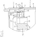
- the radii 32 and the cylinder shells 16 are designed in such a way that the cylinder shells 16 are deflected slightly outwards from the radii 32 or lie against one another without play by partially inserting a pipette tip carrier 5 from below into the circumferential side wall 2.
- the pipette tip carrier 5 is placed or clamped onto the top of the lower spacer 1.1.
- Each bore 33 has a conical section at the bottom and a cylindrical section adjacent to it.
- the dimensions of the bores 33 are selected so that the pins 10 of the spacer 1.1 can be pressed into them.
- the conical sections form insertion bevels that make it easier to insert the pins 10 into the bores 33.
- tapers at the upper ends of the pins 10 make it easier to insert them into the bores 33.
- the base body 22 is designed as a quiver plate.
- the holes 23 are formed in quiver- or sleeve-shaped structures 34, which are laterally by webs 35 and at the upper edge by a plate 36.
- An apron 37 runs around the outside of the plate 36 and the peripheral edge 29 protrudes outwards from the lower edge of the apron 37 (cf. Fig. 3 ).
- the pipette tip carrier 5 can also be designed as a web plate, whereby a thin plate with a large number of holes on the underside has webs enclosing the holes.
- the pipette tip carrier 5 can also be designed solid, ie without cavities outside the holes 23 and bores 31.
- Pipette tips 38 can be inserted into the holes 23 from above and are supported by a collar 39 on the edge of the holes.
- the pipette tip carrier 5 is preferably made in one piece. It is also preferably made of plastic. It is preferably injection-molded.
- the plastics polypropylene (PP), polycarbonate (PC), acrylonitrile-butadiene-styrene copolymers (ABS), polystyrene (PS) can be used in particular for this purpose.
- the pipette tip carrier 5 is pressed with the holes 33 onto the pins 10 of the lower spacer 1.1, so that the upper section of the pins 10 of the lower spacer 1.1 protrudes upwards with respect to the base body 22 of the pipette tip carrier 5.
- the pins 10 can also be inserted into the holes 33 with play.
- the upper spacer 1.1 rests with its base surface 4 outside the gripping edges 26, 27, 28 on the upper contact surface 30 of the pipette tip carrier 5 and the lower spacer 1.1 rests with its support surface 9 on the lower contact surface 31 of the pipette tip carrier 5.
- the protruding sections of the pins 10 are inserted into the circumferential side wall 2 of the upper spacer 1.1 and the cylinder shells 16 or bending springs 15.1 of the upper spacer 1.1 rest on the radii 32 of the pipette tip carrier 5, which the lower spacer 1.1 carries.
- the bending springs 15.1 precise centering of the spacer 1.1 on the pipette tip carrier 5 and stable stacking are achieved.
- the pins 10 have a press fit in the bores 33 or are guided therein without play.
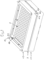
- the spacer 1.2 from Fig. 5 to 7 differs from the previously described in that at each corner 7, instead of a cylindrical shell 16, there are two vertical slots 40.1, 40.2 which start from the lower edge of the side wall 2 and end below the upper edge of the side wall 2. In the example, they end approximately halfway up the side wall 2.
- the two vertical slots 40.1, 40.2 are designed symmetrically with respect to the respective corner 7.
- the vertical slots 40.1, 40.2 each extend from the inside to the outside of the side wall 2.
- the area between the two vertical slots forms a bending element 15.2 in the form of a bending spring.
- the inner radius 13 at the corners 7 of the side wall 2 corresponds to the radius of the pin 9 or slightly exceeds it.
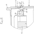
- the pins 10 and the corners 7 of the spacer 1.2 are designed in such a way that the pins 10 of another identical spacer 1.2 or 1.1 can be inserted from below into the surrounding side wall 2 and rest against the inner radii 13 of the corners 7 with the bending elements 15.2 slightly bending out. This ensures that the spacers 1.2 or 1.2 and 1.1 are precisely centered on one another and that they are stacked in a stable manner.
- the spacer 1.2 is placed with its base 4 on a pipette tip carrier 5.
- the pipette tip carrier 5 is preferably placed on the support surface 9 of another identical spacer 1.2.
- the pipette tip carrier 5 is placed on the support surface 9 of a spacer 1.1, since the different embodiments can also be combined with each other.
- the spacer 1.3 from Fig. 8 to 10 differs from the one described above in that it has only a single vertical slot 40.3 at each corner 7, which starts from the lower edge of the side wall 2 and ends at a distance from the upper edge of the side wall 2, approximately halfway up the side wall 2.
- the vertical slots 40.3 are each arranged in the middle of the corner 7.
- the areas adjacent to the slot 40.3 form bending elements 15.3, 15.4, which can be bent slightly outwards by pins 10 of a further spacer 1.3, 1.2 or 1.1 inserted from below.
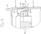
- the spacer 1.4 from Fig. 11 to 13 differs from the previously described in that at each corner 7, in addition to the vertical slot 40.3, there is a horizontal slot 40.4.
- the horizontal slot 40.4 extends from the upper end of the vertical slot 40.3 on both sides a little way into the adjacent transverse sides and longitudinal sides of the spacer 1.4.
- the horizontal slot 40.4 increases the bending softness of the bending elements 15.5, 15.6 adjacent to the vertical slot.
Landscapes
- Chemical & Material Sciences (AREA)
- Health & Medical Sciences (AREA)
- Clinical Laboratory Science (AREA)
- Chemical Kinetics & Catalysis (AREA)
- Analytical Chemistry (AREA)
- Dispersion Chemistry (AREA)
- Devices For Use In Laboratory Experiments (AREA)
Claims (18)
- Espaceur permettant de maintenir des porte-pipettes (5) en forme de plaques et essentiellement rectangulaires empilés à distance les uns des autres, dans lequel l'espaceur (1) comporte une paroi latérale circonférentielle (2), laquelle forme un cadre (3) essentiellement rectangulaire, respectivement avec deux côtés longitudinaux et deux côtés transversaux, lequel présente une surface d'appui horizontale (4) sur un bord inférieur pour l'appui sur un côté supérieur d'un porte-pipettes (5), une surface de support horizontale (9) sur un bord supérieur pour l'appui d'un autre porte-pipettes (5) sur le côté inférieur, des cônes (10) faisant saillie verticalement vers le haut à partir du bord supérieur sur des coins (7) entre des côtés longitudinaux et transversaux adjacents ainsi que des éléments de flexion (15) sur la paroi latérale, lesquels peuvent être fléchis dans une direction s'étendant en angle droit par rapport aux côtés longitudinaux et transversaux adjacents.
- Espaceur selon la revendication 1, dans lequel les éléments de flexion (15) peuvent être fléchis par des cônes (10) d'un autre espaceur (1) identique insérés par le bas et/ou par des coins ou par des rayons (32) au niveau des coins entre des côtés longitudinaux et transversaux adjacents d'un porte-pipettes (5) appuyé sur la surface de support (9) de l'autre espaceur (1).
- Espaceur selon la revendication 1 ou 2, lequel présente des éléments de flexion (15) sur au moins deux coins (7) diamétralement opposés les uns aux autres, de préférence sur tous les quatre coins.
- Espaceur selon l'une des revendications 1 à 3, dans lequel la paroi latérale circonférentielle (2) est reliée à un rebord circonférentiel (8) faisant saillie vers l'intérieur, lequel présente la surface de support (9) sur son côté supérieur.
- Espaceur selon l'une des revendications 1 à 4, dans lequel les éléments de flexion (15) présentent des coques cylindriques verticales (16) reliées à l'espaceur (1) à leurs extrémités supérieures.
- Espaceur selon la revendication 5, dans lequel les coques cylindriques (16) présentent respectivement l'une ou plusieurs des caractéristiques suivantes :• deux bords verticaux (18, 19) disposés symétriquement par rapport au coin (7),• un bord inférieur en forme d'arc de cercle (20) disposé au niveau de la surface d'appui (4) ou au-dessus de celle-ci,• un chanfrein d'entrée (21) sur le bord inférieur en forme d'arc de cercle (20) sur le côté intérieur,• une liaison avec le côté inférieur du rebord (8) à l'extrémité supérieure,• une liaison avec la paroi latérale (2) sur des sections supérieures des deux bords latéraux verticaux (18, 19).
- Espaceur selon l'une des revendications 1 à 6, dans lequel, au niveau des coins (7), les éléments de flexion (15) présentent respectivement au moins une fente verticale (40) commençant à partir du bord inférieur de la paroi latérale (2) et se terminant sous le bord supérieur dans la paroi latérale.
- Espaceur selon la revendication 7, dans lequel les fentes verticales (40) au niveau des coins (7) s'étendent respectivement à partir du côté intérieur jusqu'au côté extérieur de la paroi latérale (2).
- Espaceur selon la revendication 7 ou 8, lequel présente respectivement deux fentes verticales (40.1, 40.2) au niveau des coins (7).
- Espaceur selon la revendication 9, dans lequel les deux fentes verticales (40.1, 40.2) sont disposées respectivement symétriquement par rapport au coin (7).
- Espaceur selon la revendication 7 ou 8, dans lequel une seule fente verticale (40.3) est disposée respectivement au niveau des coins (7).
- Espaceur selon la revendication 11, dans lequel des fentes horizontales (40.4) sont disposées dans la paroi latérale (2) au niveau des coins (7), en s'étendant respectivement à partir du coin dans les deux régions adjacentes de la paroi latérale (2), et les fentes verticales (40.3) débouchent respectivement sur le haut dans la fente horizontale (40.4) au niveau du même coin (7).
- Espaceur selon l'une des revendications 1 à 12, dans lequel, au niveau des coins (7), la paroi latérale (2) présente respectivement un rayon intérieur (13) sur le côté intérieur et/ou respectivement un rayon extérieur (14) sur le côté extérieur.
- Espaceur selon l'une des revendications 1 à 13, dans lequel, au niveau des coins (7), la paroi latérale (2) présente un rayon intérieur (13) sur le côté intérieur, lequel coïncide avec le rayon du cône (10) ou dépasse celui-ci.
- Espaceur selon l'une des revendications 1 à 14, comportant l'une ou plusieurs des caractéristiques suivantes :• au niveau des coins (7), le bord supérieur du cadre (3) présente respectivement un renfoncement (11) et le cône (10) fait saillie verticalement vers le haut à partir de la surface de base du renfoncement (11),• les cônes (10) s'effilent respectivement vers l'extrémité supérieure,• les cônes (10) présentent un socle évasé (12) à l'extrémité inférieure,• au niveau des coins (7) et/ou entre ceux-ci, le cadre (3) présente des talons (6.1, 6.2) faisant saillie vers le bas, dont le bord inférieur forme au moins une partie de la surface d'appui (4),• l'espaceur (1) est constitué d'une ou de plusieurs matières plastiques,• l'espaceur (1) est constitué de polypropylène, de polyéthylène, de polycarbonate, d'un copolymère d'acrylonitrile butadiène styrène et/ou de polystyrène,• l'espaceur (1) est fabriqué par moulage par injection à partir d'une ou de plusieurs matières plastiques.
- Unité de transport pour pointes de pipette, comportant une boîte de pointes de pipette, un porte-pipettes (5) placé sur la boîte de pointes de pipette, lequel est pourvu de pointes de pipette, et au moins un ensemble placé sur le porte-pipettes (5), constitué d'un espaceur (1) selon l'une des revendications 1 à 14 et d'un autre porte-pipettes (5) placé sur l'espaceur (1) et pourvu de pointes de pipette.
- Unité de transport selon la revendication 16, dans laquelle un couvercle est placé sur un porte-pipettes (5) ou sur un espaceur (1) placé sur un porte-pipettes (5).
- Utilisation d'un espaceur selon l'une des revendications 1 à 15 pour la formation d'une pile de porte-pipettes (5) maintenus à distance les uns des autres au moyen d'espaceurs (1) et pourvus de pointes de pipette.
Priority Applications (3)
| Application Number | Priority Date | Filing Date | Title |
|---|---|---|---|
| EP21211549.7A EP4190452B1 (fr) | 2021-12-01 | 2021-12-01 | Espaceur permettant de maintenir les porte-pipettes empilés à distance les uns des autres |
| US18/714,876 US20250025881A1 (en) | 2021-12-01 | 2022-11-18 | Spacer for holding pipette tip carriers, which are stacked one over the other, spaced apart |
| PCT/EP2022/082451 WO2023099243A1 (fr) | 2021-12-01 | 2022-11-18 | Entretoise pour maintenir espacés des supports de pointes de pipette qui sont empilés les uns sur les autres |
Applications Claiming Priority (1)
| Application Number | Priority Date | Filing Date | Title |
|---|---|---|---|
| EP21211549.7A EP4190452B1 (fr) | 2021-12-01 | 2021-12-01 | Espaceur permettant de maintenir les porte-pipettes empilés à distance les uns des autres |
Publications (2)
| Publication Number | Publication Date |
|---|---|
| EP4190452A1 EP4190452A1 (fr) | 2023-06-07 |
| EP4190452B1 true EP4190452B1 (fr) | 2024-07-24 |
Family
ID=78820823
Family Applications (1)
| Application Number | Title | Priority Date | Filing Date |
|---|---|---|---|
| EP21211549.7A Active EP4190452B1 (fr) | 2021-12-01 | 2021-12-01 | Espaceur permettant de maintenir les porte-pipettes empilés à distance les uns des autres |
Country Status (3)
| Country | Link |
|---|---|
| US (1) | US20250025881A1 (fr) |
| EP (1) | EP4190452B1 (fr) |
| WO (1) | WO2023099243A1 (fr) |
Families Citing this family (3)
| Publication number | Priority date | Publication date | Assignee | Title |
|---|---|---|---|---|
| EP4491276A1 (fr) * | 2024-04-11 | 2025-01-15 | TECAN Trading AG | Porte-pointes de pipette de forme rectangulaire pour contenir une pluralité de pointes de pipette |
| EP4491275A1 (fr) | 2024-04-11 | 2025-01-15 | TECAN Trading AG | Espaceur en forme de cadre pour porte-pointes de pipette |
| USD1112806S1 (en) * | 2024-11-15 | 2026-02-10 | Cytiva Us Llc | Tangential flow filtration cassette |
Family Cites Families (4)
| Publication number | Priority date | Publication date | Assignee | Title |
|---|---|---|---|---|
| US8551955B2 (en) | 2009-10-28 | 2013-10-08 | Joyant Pharmaceuticals, Inc. | Dimeric Smac mimetics |
| EP2839880A1 (fr) | 2013-08-20 | 2015-02-25 | Eppendorf Ag | Support pour embouts de pipette |
| CH709054A1 (de) | 2013-12-20 | 2015-06-30 | Tecan Trading Ag | Abstandhalter für übereinandergestapelte Pipettenspitzen-Träger. |
| DE202014100076U1 (de) * | 2014-01-09 | 2014-01-28 | Tecan Trading Ag | Abstandhalter für übereinander gestapelte Pipettenspitzen-Träger |
-
2021
- 2021-12-01 EP EP21211549.7A patent/EP4190452B1/fr active Active
-
2022
- 2022-11-18 US US18/714,876 patent/US20250025881A1/en active Pending
- 2022-11-18 WO PCT/EP2022/082451 patent/WO2023099243A1/fr not_active Ceased
Also Published As
| Publication number | Publication date |
|---|---|
| WO2023099243A1 (fr) | 2023-06-08 |
| EP4190452A1 (fr) | 2023-06-07 |
| US20250025881A1 (en) | 2025-01-23 |
Similar Documents
| Publication | Publication Date | Title |
|---|---|---|
| EP4190452B1 (fr) | Espaceur permettant de maintenir les porte-pipettes empilés à distance les uns des autres | |
| EP2355932B1 (fr) | Support pour une unité d'échantillonnage | |
| EP2789389B1 (fr) | Dispositif pour stockage et pour fournir des embouts de pipette | |
| EP3320975B1 (fr) | Dispositif de mise en place d'embouts de pipette | |
| EP2848308B1 (fr) | Écarteur pour support pour pointes de pipettes empilées les unes sur les autres | |
| DE69101611T2 (de) | Gerät zur Behandlung biologischer Proben. | |
| DE102004003439A1 (de) | Farbbechersystem für eine Farbspritzpistole | |
| WO1997019866A1 (fr) | Plateau de transport de boites de boissons | |
| DE202020100836U1 (de) | Magazin für Pipettiervorrichtung | |
| WO2017013114A1 (fr) | Maintien en position d'un catheter | |
| EP4019137A1 (fr) | Cadre permettant de loger une plaque de support pour pointes de pipette | |
| EP3230014B1 (fr) | Caisse destinée à recevoir des outils ou de petites pièces | |
| EP0630312A1 (fr) | Unite de prehension pour robots de manutention | |
| EP4331723B1 (fr) | Ensemble comprenant une microplaque, un couvercle et un dispositif de libération d'une liaison encliquetable entre la microplaque et le couvercle | |
| EP3257619B1 (fr) | Magasin pour vis | |
| EP1963193A1 (fr) | Dispositif de fermeture universelle | |
| WO2026068308A1 (fr) | Support pour soutenir une pluralité de pointes de pipette | |
| EP0550839B1 (fr) | Boîte de jonction en forme de caisson pour câble électronique | |
| EP1938904A1 (fr) | Dispositif de support pour le recouvrement de la cuve d'une fontaine ou d'un puits | |
| EP1014374A1 (fr) | Contenair, pour stockage d'un disque circulaire, contenant de l'information, qui peut être fermer, spéciallement pour un disque compact contenant de l'information numérique | |
| WO2007082697A1 (fr) | Groupe de supports de réactifs combinés sous la forme d'un assemblage | |
| DE29922006U1 (de) | Verbindungselement für Trennwände zur Facheinteilung einer Schublade | |
| DE202014100076U1 (de) | Abstandhalter für übereinander gestapelte Pipettenspitzen-Träger | |
| EP0428961A1 (fr) | Douille d'ancrage dans le sol pour la réception d'un pied d'un agrès sportif | |
| DE29610935U1 (de) | Transport- und Kultivationspalette |
Legal Events
| Date | Code | Title | Description |
|---|---|---|---|
| PUAI | Public reference made under article 153(3) epc to a published international application that has entered the european phase |
Free format text: ORIGINAL CODE: 0009012 |
|
| STAA | Information on the status of an ep patent application or granted ep patent |
Free format text: STATUS: THE APPLICATION HAS BEEN PUBLISHED |
|
| AK | Designated contracting states |
Kind code of ref document: A1 Designated state(s): AL AT BE BG CH CY CZ DE DK EE ES FI FR GB GR HR HU IE IS IT LI LT LU LV MC MK MT NL NO PL PT RO RS SE SI SK SM TR |
|
| STAA | Information on the status of an ep patent application or granted ep patent |
Free format text: STATUS: REQUEST FOR EXAMINATION WAS MADE |
|
| 17P | Request for examination filed |
Effective date: 20231207 |
|
| RBV | Designated contracting states (corrected) |
Designated state(s): AL AT BE BG CH CY CZ DE DK EE ES FI FR GB GR HR HU IE IS IT LI LT LU LV MC MK MT NL NO PL PT RO RS SE SI SK SM TR |
|
| GRAP | Despatch of communication of intention to grant a patent |
Free format text: ORIGINAL CODE: EPIDOSNIGR1 |
|
| STAA | Information on the status of an ep patent application or granted ep patent |
Free format text: STATUS: GRANT OF PATENT IS INTENDED |
|
| RIC1 | Information provided on ipc code assigned before grant |
Ipc: B01L 3/02 20060101ALI20240220BHEP Ipc: B01L 9/00 20060101AFI20240220BHEP |
|
| INTG | Intention to grant announced |
Effective date: 20240312 |
|
| GRAS | Grant fee paid |
Free format text: ORIGINAL CODE: EPIDOSNIGR3 |
|
| GRAA | (expected) grant |
Free format text: ORIGINAL CODE: 0009210 |
|
| STAA | Information on the status of an ep patent application or granted ep patent |
Free format text: STATUS: THE PATENT HAS BEEN GRANTED |
|
| AK | Designated contracting states |
Kind code of ref document: B1 Designated state(s): AL AT BE BG CH CY CZ DE DK EE ES FI FR GB GR HR HU IE IS IT LI LT LU LV MC MK MT NL NO PL PT RO RS SE SI SK SM TR |
|
| REG | Reference to a national code |
Ref country code: GB Ref legal event code: FG4D Free format text: NOT ENGLISH |
|
| REG | Reference to a national code |
Ref country code: CH Ref legal event code: EP |
|
| REG | Reference to a national code |
Ref country code: DE Ref legal event code: R096 Ref document number: 502021004483 Country of ref document: DE |
|
| REG | Reference to a national code |
Ref country code: IE Ref legal event code: FG4D Free format text: LANGUAGE OF EP DOCUMENT: GERMAN |
|
| REG | Reference to a national code |
Ref country code: LT Ref legal event code: MG9D |
|
| REG | Reference to a national code |
Ref country code: NL Ref legal event code: MP Effective date: 20240724 |
|
| PG25 | Lapsed in a contracting state [announced via postgrant information from national office to epo] |
Ref country code: PT Free format text: LAPSE BECAUSE OF FAILURE TO SUBMIT A TRANSLATION OF THE DESCRIPTION OR TO PAY THE FEE WITHIN THE PRESCRIBED TIME-LIMIT Effective date: 20241125 |
|
| PG25 | Lapsed in a contracting state [announced via postgrant information from national office to epo] |
Ref country code: NL Free format text: LAPSE BECAUSE OF FAILURE TO SUBMIT A TRANSLATION OF THE DESCRIPTION OR TO PAY THE FEE WITHIN THE PRESCRIBED TIME-LIMIT Effective date: 20240724 |
|
| PG25 | Lapsed in a contracting state [announced via postgrant information from national office to epo] |
Ref country code: PT Free format text: LAPSE BECAUSE OF FAILURE TO SUBMIT A TRANSLATION OF THE DESCRIPTION OR TO PAY THE FEE WITHIN THE PRESCRIBED TIME-LIMIT Effective date: 20241125 Ref country code: NL Free format text: LAPSE BECAUSE OF FAILURE TO SUBMIT A TRANSLATION OF THE DESCRIPTION OR TO PAY THE FEE WITHIN THE PRESCRIBED TIME-LIMIT Effective date: 20240724 |
|
| PG25 | Lapsed in a contracting state [announced via postgrant information from national office to epo] |
Ref country code: NO Free format text: LAPSE BECAUSE OF FAILURE TO SUBMIT A TRANSLATION OF THE DESCRIPTION OR TO PAY THE FEE WITHIN THE PRESCRIBED TIME-LIMIT Effective date: 20241024 |
|
| PG25 | Lapsed in a contracting state [announced via postgrant information from national office to epo] |
Ref country code: FI Free format text: LAPSE BECAUSE OF FAILURE TO SUBMIT A TRANSLATION OF THE DESCRIPTION OR TO PAY THE FEE WITHIN THE PRESCRIBED TIME-LIMIT Effective date: 20240724 Ref country code: GR Free format text: LAPSE BECAUSE OF FAILURE TO SUBMIT A TRANSLATION OF THE DESCRIPTION OR TO PAY THE FEE WITHIN THE PRESCRIBED TIME-LIMIT Effective date: 20241025 Ref country code: PL Free format text: LAPSE BECAUSE OF FAILURE TO SUBMIT A TRANSLATION OF THE DESCRIPTION OR TO PAY THE FEE WITHIN THE PRESCRIBED TIME-LIMIT Effective date: 20240724 |
|
| PG25 | Lapsed in a contracting state [announced via postgrant information from national office to epo] |
Ref country code: BG Free format text: LAPSE BECAUSE OF FAILURE TO SUBMIT A TRANSLATION OF THE DESCRIPTION OR TO PAY THE FEE WITHIN THE PRESCRIBED TIME-LIMIT Effective date: 20240724 |
|
| PG25 | Lapsed in a contracting state [announced via postgrant information from national office to epo] |
Ref country code: LV Free format text: LAPSE BECAUSE OF FAILURE TO SUBMIT A TRANSLATION OF THE DESCRIPTION OR TO PAY THE FEE WITHIN THE PRESCRIBED TIME-LIMIT Effective date: 20240724 |
|
| PG25 | Lapsed in a contracting state [announced via postgrant information from national office to epo] |
Ref country code: IS Free format text: LAPSE BECAUSE OF FAILURE TO SUBMIT A TRANSLATION OF THE DESCRIPTION OR TO PAY THE FEE WITHIN THE PRESCRIBED TIME-LIMIT Effective date: 20241124 |
|
| PG25 | Lapsed in a contracting state [announced via postgrant information from national office to epo] |
Ref country code: HR Free format text: LAPSE BECAUSE OF FAILURE TO SUBMIT A TRANSLATION OF THE DESCRIPTION OR TO PAY THE FEE WITHIN THE PRESCRIBED TIME-LIMIT Effective date: 20240724 |
|
| PG25 | Lapsed in a contracting state [announced via postgrant information from national office to epo] |
Ref country code: RS Free format text: LAPSE BECAUSE OF FAILURE TO SUBMIT A TRANSLATION OF THE DESCRIPTION OR TO PAY THE FEE WITHIN THE PRESCRIBED TIME-LIMIT Effective date: 20241024 Ref country code: ES Free format text: LAPSE BECAUSE OF FAILURE TO SUBMIT A TRANSLATION OF THE DESCRIPTION OR TO PAY THE FEE WITHIN THE PRESCRIBED TIME-LIMIT Effective date: 20240724 |
|
| PG25 | Lapsed in a contracting state [announced via postgrant information from national office to epo] |
Ref country code: RS Free format text: LAPSE BECAUSE OF FAILURE TO SUBMIT A TRANSLATION OF THE DESCRIPTION OR TO PAY THE FEE WITHIN THE PRESCRIBED TIME-LIMIT Effective date: 20241024 Ref country code: PL Free format text: LAPSE BECAUSE OF FAILURE TO SUBMIT A TRANSLATION OF THE DESCRIPTION OR TO PAY THE FEE WITHIN THE PRESCRIBED TIME-LIMIT Effective date: 20240724 Ref country code: NO Free format text: LAPSE BECAUSE OF FAILURE TO SUBMIT A TRANSLATION OF THE DESCRIPTION OR TO PAY THE FEE WITHIN THE PRESCRIBED TIME-LIMIT Effective date: 20241024 Ref country code: LV Free format text: LAPSE BECAUSE OF FAILURE TO SUBMIT A TRANSLATION OF THE DESCRIPTION OR TO PAY THE FEE WITHIN THE PRESCRIBED TIME-LIMIT Effective date: 20240724 Ref country code: IS Free format text: LAPSE BECAUSE OF FAILURE TO SUBMIT A TRANSLATION OF THE DESCRIPTION OR TO PAY THE FEE WITHIN THE PRESCRIBED TIME-LIMIT Effective date: 20241124 Ref country code: HR Free format text: LAPSE BECAUSE OF FAILURE TO SUBMIT A TRANSLATION OF THE DESCRIPTION OR TO PAY THE FEE WITHIN THE PRESCRIBED TIME-LIMIT Effective date: 20240724 Ref country code: GR Free format text: LAPSE BECAUSE OF FAILURE TO SUBMIT A TRANSLATION OF THE DESCRIPTION OR TO PAY THE FEE WITHIN THE PRESCRIBED TIME-LIMIT Effective date: 20241025 Ref country code: FI Free format text: LAPSE BECAUSE OF FAILURE TO SUBMIT A TRANSLATION OF THE DESCRIPTION OR TO PAY THE FEE WITHIN THE PRESCRIBED TIME-LIMIT Effective date: 20240724 Ref country code: ES Free format text: LAPSE BECAUSE OF FAILURE TO SUBMIT A TRANSLATION OF THE DESCRIPTION OR TO PAY THE FEE WITHIN THE PRESCRIBED TIME-LIMIT Effective date: 20240724 Ref country code: BG Free format text: LAPSE BECAUSE OF FAILURE TO SUBMIT A TRANSLATION OF THE DESCRIPTION OR TO PAY THE FEE WITHIN THE PRESCRIBED TIME-LIMIT Effective date: 20240724 |
|
| PG25 | Lapsed in a contracting state [announced via postgrant information from national office to epo] |
Ref country code: SM Free format text: LAPSE BECAUSE OF FAILURE TO SUBMIT A TRANSLATION OF THE DESCRIPTION OR TO PAY THE FEE WITHIN THE PRESCRIBED TIME-LIMIT Effective date: 20240724 Ref country code: DK Free format text: LAPSE BECAUSE OF FAILURE TO SUBMIT A TRANSLATION OF THE DESCRIPTION OR TO PAY THE FEE WITHIN THE PRESCRIBED TIME-LIMIT Effective date: 20240724 Ref country code: RO Free format text: LAPSE BECAUSE OF FAILURE TO SUBMIT A TRANSLATION OF THE DESCRIPTION OR TO PAY THE FEE WITHIN THE PRESCRIBED TIME-LIMIT Effective date: 20240724 |
|
| PG25 | Lapsed in a contracting state [announced via postgrant information from national office to epo] |
Ref country code: EE Free format text: LAPSE BECAUSE OF FAILURE TO SUBMIT A TRANSLATION OF THE DESCRIPTION OR TO PAY THE FEE WITHIN THE PRESCRIBED TIME-LIMIT Effective date: 20240724 |
|
| PG25 | Lapsed in a contracting state [announced via postgrant information from national office to epo] |
Ref country code: CZ Free format text: LAPSE BECAUSE OF FAILURE TO SUBMIT A TRANSLATION OF THE DESCRIPTION OR TO PAY THE FEE WITHIN THE PRESCRIBED TIME-LIMIT Effective date: 20240724 |
|
| REG | Reference to a national code |
Ref country code: DE Ref legal event code: R097 Ref document number: 502021004483 Country of ref document: DE |
|
| PG25 | Lapsed in a contracting state [announced via postgrant information from national office to epo] |
Ref country code: SK Free format text: LAPSE BECAUSE OF FAILURE TO SUBMIT A TRANSLATION OF THE DESCRIPTION OR TO PAY THE FEE WITHIN THE PRESCRIBED TIME-LIMIT Effective date: 20240724 Ref country code: IT Free format text: LAPSE BECAUSE OF FAILURE TO SUBMIT A TRANSLATION OF THE DESCRIPTION OR TO PAY THE FEE WITHIN THE PRESCRIBED TIME-LIMIT Effective date: 20240724 |
|
| PLBE | No opposition filed within time limit |
Free format text: ORIGINAL CODE: 0009261 |
|
| STAA | Information on the status of an ep patent application or granted ep patent |
Free format text: STATUS: NO OPPOSITION FILED WITHIN TIME LIMIT |
|
| 26N | No opposition filed |
Effective date: 20250425 |
|
| PG25 | Lapsed in a contracting state [announced via postgrant information from national office to epo] |
Ref country code: MC Free format text: LAPSE BECAUSE OF FAILURE TO SUBMIT A TRANSLATION OF THE DESCRIPTION OR TO PAY THE FEE WITHIN THE PRESCRIBED TIME-LIMIT Effective date: 20240724 |
|
| REG | Reference to a national code |
Ref country code: CH Ref legal event code: PL |
|
| PG25 | Lapsed in a contracting state [announced via postgrant information from national office to epo] |
Ref country code: LU Free format text: LAPSE BECAUSE OF NON-PAYMENT OF DUE FEES Effective date: 20241201 |
|
| PG25 | Lapsed in a contracting state [announced via postgrant information from national office to epo] |
Ref country code: SE Free format text: LAPSE BECAUSE OF FAILURE TO SUBMIT A TRANSLATION OF THE DESCRIPTION OR TO PAY THE FEE WITHIN THE PRESCRIBED TIME-LIMIT Effective date: 20240724 |
|
| REG | Reference to a national code |
Ref country code: BE Ref legal event code: MM Effective date: 20241231 |
|
| PG25 | Lapsed in a contracting state [announced via postgrant information from national office to epo] |
Ref country code: BE Free format text: LAPSE BECAUSE OF NON-PAYMENT OF DUE FEES Effective date: 20241231 |
|
| PG25 | Lapsed in a contracting state [announced via postgrant information from national office to epo] |
Ref country code: CH Free format text: LAPSE BECAUSE OF NON-PAYMENT OF DUE FEES Effective date: 20241231 |
|
| PG25 | Lapsed in a contracting state [announced via postgrant information from national office to epo] |
Ref country code: IE Free format text: LAPSE BECAUSE OF NON-PAYMENT OF DUE FEES Effective date: 20241201 |
|
| PGFP | Annual fee paid to national office [announced via postgrant information from national office to epo] |
Ref country code: DE Payment date: 20251211 Year of fee payment: 5 |
|
| PGFP | Annual fee paid to national office [announced via postgrant information from national office to epo] |
Ref country code: GB Payment date: 20251219 Year of fee payment: 5 |
|
| PGFP | Annual fee paid to national office [announced via postgrant information from national office to epo] |
Ref country code: AT Payment date: 20260113 Year of fee payment: 5 |
|
| PGFP | Annual fee paid to national office [announced via postgrant information from national office to epo] |
Ref country code: FR Payment date: 20251229 Year of fee payment: 5 |
|
| PG25 | Lapsed in a contracting state [announced via postgrant information from national office to epo] |
Ref country code: CY Free format text: LAPSE BECAUSE OF FAILURE TO SUBMIT A TRANSLATION OF THE DESCRIPTION OR TO PAY THE FEE WITHIN THE PRESCRIBED TIME-LIMIT; INVALID AB INITIO Effective date: 20211201 |