EP4331723B1 - Ensemble comprenant une microplaque, un couvercle et un dispositif de libération d'une liaison encliquetable entre la microplaque et le couvercle - Google Patents
Ensemble comprenant une microplaque, un couvercle et un dispositif de libération d'une liaison encliquetable entre la microplaque et le couvercle Download PDFInfo
- Publication number
- EP4331723B1 EP4331723B1 EP22193653.7A EP22193653A EP4331723B1 EP 4331723 B1 EP4331723 B1 EP 4331723B1 EP 22193653 A EP22193653 A EP 22193653A EP 4331723 B1 EP4331723 B1 EP 4331723B1
- Authority
- EP
- European Patent Office
- Prior art keywords
- plate
- snap
- microplate
- lid
- set according
- Prior art date
- Legal status (The legal status is an assumption and is not a legal conclusion. Google has not performed a legal analysis and makes no representation as to the accuracy of the status listed.)
- Active
Links
Images


Classifications
-
- B—PERFORMING OPERATIONS; TRANSPORTING
- B01—PHYSICAL OR CHEMICAL PROCESSES OR APPARATUS IN GENERAL
- B01L—CHEMICAL OR PHYSICAL LABORATORY APPARATUS FOR GENERAL USE
- B01L3/00—Containers or dishes for laboratory use, e.g. laboratory glassware; Droppers
- B01L3/50—Containers for the purpose of retaining a material to be analysed, e.g. test tubes
- B01L3/508—Rigid containers without fluid transport within
- B01L3/5085—Rigid containers without fluid transport within for multiple samples, e.g. microtitration plates
- B01L3/50853—Rigid containers without fluid transport within for multiple samples, e.g. microtitration plates with covers or lids
-
- C—CHEMISTRY; METALLURGY
- C12—BIOCHEMISTRY; BEER; SPIRITS; WINE; VINEGAR; MICROBIOLOGY; ENZYMOLOGY; MUTATION OR GENETIC ENGINEERING
- C12M—APPARATUS FOR ENZYMOLOGY OR MICROBIOLOGY; APPARATUS FOR CULTURING MICROORGANISMS FOR PRODUCING BIOMASS, FOR GROWING CELLS OR FOR OBTAINING FERMENTATION OR METABOLIC PRODUCTS, i.e. BIOREACTORS OR FERMENTERS
- C12M23/00—Constructional details, e.g. recesses, hinges
- C12M23/02—Form or structure of the vessel
- C12M23/12—Well or multiwell plates
-
- C—CHEMISTRY; METALLURGY
- C12—BIOCHEMISTRY; BEER; SPIRITS; WINE; VINEGAR; MICROBIOLOGY; ENZYMOLOGY; MUTATION OR GENETIC ENGINEERING
- C12M—APPARATUS FOR ENZYMOLOGY OR MICROBIOLOGY; APPARATUS FOR CULTURING MICROORGANISMS FOR PRODUCING BIOMASS, FOR GROWING CELLS OR FOR OBTAINING FERMENTATION OR METABOLIC PRODUCTS, i.e. BIOREACTORS OR FERMENTERS
- C12M23/00—Constructional details, e.g. recesses, hinges
- C12M23/38—Caps; Covers; Plugs; Pouring means
-
- B—PERFORMING OPERATIONS; TRANSPORTING
- B01—PHYSICAL OR CHEMICAL PROCESSES OR APPARATUS IN GENERAL
- B01L—CHEMICAL OR PHYSICAL LABORATORY APPARATUS FOR GENERAL USE
- B01L2200/00—Solutions for specific problems relating to chemical or physical laboratory apparatus
- B01L2200/02—Adapting objects or devices to another
- B01L2200/025—Align devices or objects to ensure defined positions relative to each other
-
- B—PERFORMING OPERATIONS; TRANSPORTING
- B01—PHYSICAL OR CHEMICAL PROCESSES OR APPARATUS IN GENERAL
- B01L—CHEMICAL OR PHYSICAL LABORATORY APPARATUS FOR GENERAL USE
- B01L2200/00—Solutions for specific problems relating to chemical or physical laboratory apparatus
- B01L2200/06—Fluid handling related problems
- B01L2200/0689—Sealing
-
- B—PERFORMING OPERATIONS; TRANSPORTING
- B01—PHYSICAL OR CHEMICAL PROCESSES OR APPARATUS IN GENERAL
- B01L—CHEMICAL OR PHYSICAL LABORATORY APPARATUS FOR GENERAL USE
- B01L2300/00—Additional constructional details
- B01L2300/04—Closures and closing means
- B01L2300/041—Connecting closures to device or container
-
- B—PERFORMING OPERATIONS; TRANSPORTING
- B01—PHYSICAL OR CHEMICAL PROCESSES OR APPARATUS IN GENERAL
- B01L—CHEMICAL OR PHYSICAL LABORATORY APPARATUS FOR GENERAL USE
- B01L2300/00—Additional constructional details
- B01L2300/04—Closures and closing means
- B01L2300/041—Connecting closures to device or container
- B01L2300/042—Caps; Plugs
-
- B—PERFORMING OPERATIONS; TRANSPORTING
- B01—PHYSICAL OR CHEMICAL PROCESSES OR APPARATUS IN GENERAL
- B01L—CHEMICAL OR PHYSICAL LABORATORY APPARATUS FOR GENERAL USE
- B01L2300/00—Additional constructional details
- B01L2300/08—Geometry, shape and general structure
- B01L2300/0809—Geometry, shape and general structure rectangular shaped
- B01L2300/0829—Multi-well plates; Microtitration plates
-
- B—PERFORMING OPERATIONS; TRANSPORTING
- B01—PHYSICAL OR CHEMICAL PROCESSES OR APPARATUS IN GENERAL
- B01L—CHEMICAL OR PHYSICAL LABORATORY APPARATUS FOR GENERAL USE
- B01L2300/00—Additional constructional details
- B01L2300/12—Specific details about materials
- B01L2300/123—Flexible; Elastomeric
Definitions
- the invention relates to a set comprising a microplate, also called microtiter plate, microtest plate or multiwell plate, a lid for covering the microplate and a device for releasing a snap connection between the microplate and the lid.
- Microplates are used primarily in scientific and industrial laboratories with medical, molecular biology, or pharmaceutical applications for a wide variety of microbiological, cell biology, and immunological procedures. For example, microplates are used in PCR and the cultivation of microorganisms or cells.
- Microplates have a frame with numerous wells for receiving sample liquid. Common designs include depressions in a plate-shaped frame. In other designs, the wells are connected to a plate of the frame at the top, project downward from the bottom of the plate, and have an opening at the top of the plate. The outer edge of the plate may be connected to a downwardly projecting, circumferential side wall of the frame. The side wall may project further downward from the plate than the wells ( skirted ). Other designs are also known in which the side wall projects less far downward from the plate than the wells ( semi-skirted ). However, there are designs in which the plate is not connected to a side wall ( unskirted ). Common microplates with a side wall have an extension at the bottom of the side wall, allowing them to be placed on top of another microplate. Microplates with large wells are also called “deepwell plates.”
- Microplates are standardized by the ANSI/SLAS standards for microplates, particularly with regard to footprint and the arrangement of the wells for microplates with 96, 384, and 1,536 wells. Microplates with 96 wells are particularly common, with the wells arranged in eight rows and twelve columns, each spaced 9 mm apart.
- microplates and deep-well plates with 48 wells arranged in six rows and eight columns, which are used, for example, for cell cultures. These microplates are offered with the same footprint, or length and width, as the 96-well microplates, according to ANSI/SLAS standards for microplates.
- the DE 100 66 431 B4 describes a plastic microplate with a rigid lid that can be removably attached to the top of the plate and at least one seal made of an elastic material between the lid and the plate.
- plug-shaped seals protrude from the underside of the plate and engage in openings in the vessels so that they rest sealingly against the inner wall of the vessels with sealing beads on their outer circumference when the lid is placed on the microplate.
- the lid has borders that project downwards from the edge of the plate, from which locking projections protrude inwards and can be snapped into recesses in the side wall below the plate of the microplate.
- the borders of the lid have upwardly projecting handles that make it easier to grasp the lid. By pivoting the handles, the locking connection between the locking projections and the recesses can be released because the borders pivot with the handles.
- the microplate and the lid are not suitable for automated plate handling, particularly because the snap connection can be released by the handles.
- the invention is based on the object of providing a technology that enables a simple dissolution of a snap connection between microplate and lid, which can also be carried out in an automated process.
- the lid is placed onto the microplate from above to cover the openings of the vessels and to protect the liquid filled into the vessels from loss or contamination.
- the snap hooks are inserted into the snap openings until they engage behind the edge areas of the first plate adjacent to the snap openings, thereby forming snap connections between the microplate and the lid.
- the lid can be removed from the microplate again by placing the microplate with the lid snapped onto the release device for releasing the snap connections ("release device").
- release device When placing the microplate with the snapped lid onto the Unlocking device, the snap hooks are deflected outwards by sliding the second sliding surfaces on the first sliding surfaces and the Snap connections are released. Simply placing the microplate, closed by the lid, onto the release mechanism releases the snap connections, and the lid can be lifted off the microplate in one more movement.
- the snap connections between the microplate and the lid can be easily established. Furthermore, the snap connections can be easily released by placing the microplate, together with the lid snapped onto it, onto the release device. Furthermore, it is possible to handle the lid automatically.
- the microplate can be closed and snapped shut by the lid by simply placing the lid onto the microplate using a machine.
- the snap connection can be released by simply placing the microplate covered by the lid onto the release device using a machine. Manual handling is also possible.
- microplates can be used with the set without modification.
- the set can be used with existing microplates as well as customized microplates and deep-well plates.
- the connection and disconnection of the snap connections can be automated using a laboratory automation system or dispensing machine, or manually performed by laboratory personnel.
- each snap connection is arranged at least partially in the two lateral edges of the first plate. This facilitates the release of the snap connection by deflecting the snap hooks outward, because the snap hooks are released by their ends entering the snap openings of a first plate.
- the snap openings can be formed exclusively in the lateral edges of the first plate, particularly in a microplate that does not have a side wall.
- a microplate with a side wall can also have the snap openings exclusively in the first plate, whereby the snap openings must be large enough for the snap hooks to be deflected until they no longer engage beneath the first plate and can be pulled out of the snap openings.
- the microplate comprises a circumferential side wall projecting downward from the outer edge of the first plate, and each snap opening is formed at least partially in the upper edge region of the side wall.
- the at least partial formation of each snap opening in the upper edge region of the side wall facilitates the release of the snap connections by lateral deflection of the snap hooks.
- each snap opening is arranged partly in the lateral edge region of the first plate and partly in the upper edge region of the side wall.
- the snap openings can also be formed exclusively in the side wall.
- the portion of the snap openings formed in the lateral edge region of the first plate has an upper boundary surface running parallel to the outer edge of the first plate, which is aligned with the inner side of the side wall or offset inwardly relative thereto, and which adjoins a lower boundary surface of the portion of the snap opening in the upper edge region of the side wall. This facilitates demolding of the microplate from the injection mold during injection molding.
- the microplate has two snap-in openings on each of the two long edges of the first plate, and the lid has two snap-in hooks on each of the two long edges of the second plate. This promotes a uniform, sealing fit of the lid to the microplate.
- the microplate has two snap-in openings on each of its two short edges, and the lid has two snap-in hooks on each of its two short edges. This further promotes the even contact of the lid with the microplate.
- the snap hooks have a vertical bar and, at the lower end of the vertical bar, an inwardly projecting horizontal bar. This creates flexible snap hooks that allow for easy snapping into the snap openings and easy, targeted release.
- the horizontal web has a first sliding surface at the outer end on the underside.
- the second plate has a recess on the lateral edges next to the connection with the snap-in hook, above the end of the snap-in hook. This facilitates the removal of the lid from a mold during injection molding.
- the microplate and/or the lid comprises at least one sealing element that seals the edge of each opening all the way around when the lid has snap connections with the microplate. This improves the tight closure of the vessels by the lid in the sealed position.
- the sealing element is, for example, an elastic flat material or an elastic material layer on the underside of the lid, which seals all openings of the microplate when the lid is snapped onto the microplate.
- the lid has sealing elements (covers) arranged in rows and columns on the underside of the second plate, each of which rests against an inner edge of one of the openings when the lid is snapped onto the microplate.
- the sealing elements have, for example, a circular or annular base and rest circumferentially sealingly against the edge of the openings in the first plate and/or adjacent to the openings in the inner wall of the vessels.
- the sealing elements protrude downwards from the underside of the lid.
- each sealing element is dome-shaped (e.g., hemispherical) or conical. This further improves the sealing of the container openings by the lid in the covering position.
- the grid of covers is cambered.
- the inner covers are higher than the outer covers. This is advantageous for sealing a grid of covers, as it allows a deformed grid to lie flat against the grid. In other words, the most or first deformed areas in the center of the grid give way, and only then do they make contact with the later deformed areas at the edges.
- the first plate has at least one further snap opening between the lateral edges
- the lid has at least one further downwardly projecting snap hook between the two lateral edges of the second plate.
- the further snap hook is inserted into the further snap opening and snaps behind it to the underside of the first plate when the lid with the second plate rests against the top of the first plate of the microplate.
- the further snap hook has at least one further first sliding surface.
- the unlocking device for releasing the snap connections has a further second sliding surface that is designed to slide along the further first sliding surface when the microplate is placed on top with the snapped-on lid, thereby releasing the snap connection. This further improves the sealing of the lid against the microplate in the covering position.
- snap hooks which are arranged not on the edge but between the vessels, can support the holding force and the even distribution of the locking effect.
- the snap hooks of the lid can be arranged not only on the edge but also between the wells. This allows the covers to be pressed more effectively against the edges of the openings on the top of the first plate, creating a more reliable seal. For this to happen, additional snap-in openings (breakthroughs) must be provided in the first plate, into which the additional snap-in hooks also engage.
- the principle of locking by means of snap hooks and unlocking by displacement using sliding surfaces on the unlocking block is also used here.
- the unlocking device has a rectangular frame, the support projections are formed by frame strips of the frame, and the receptacle is formed by the inner sides of the frame. This enables a particularly simple design.
- the microplate and/or the lid and/or the release device are injection-molded.
- the microplate and/or the lid are manufactured using a single-component or multi-component injection molding process.
- the microplate and/or the lid and/or the release device is vacuum-formed and/or made of injection-molded and vacuum-formed components assembled and/or hot-stamped.
- the vessels have a volume of 0.5, 1.0, 1.2, 1.5, 1.8, 2.0 or 2.5 ml each.
- the microplate has 12, 24, 48, 96 or 384 wells.
- the microplate is an ANSI/SLS microplate with 96, 384 or 1,536 wells or a deepwell plate.
- the terms “horizontal” and “vertical” as well as “top” and “bottom” refer to an arrangement of the microplate with the edge of the side wall facing away from the first plate on a horizontal base and the lid on the top of the microplate.
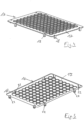
- a microplate 1 comprises a rectangular first plate 2 and a circumferential side wall 4 with four sides 4.1 to 4.4, projecting downward from the outer edge 3 of the first plate 2.
- the first plate 2 and the side wall 4 are also referred to as a "frame.”
- 96 vessels 5 are arranged in eight rows and twelve columns, which are connected to the top of the first plate 2, project downwards from the underside of the first plate 2 and have an opening 6 at the top of the first plate 2.
- Each opening 6 is surrounded by a small border 7 which projects upwards from the top of the first plate 2.
- the vessels 5 have a downwardly tapering shape. They have a conical vessel section 5.1 connected to the first plate 2 at the top with diameter decreasing at the bottom and a first downwardly curved, spherical bowl-shaped vessel bottom 5.2.
- the side wall 4 has an outwardly projecting flange 8 at the lower edge. In vertical section, this has an inverted L-profile and forms an outwardly and downwardly projecting extension 9 of the side wall 4.
- the microplate 1 has snap openings 10 at the edge of the first plate 2.
- Each snap opening 10 is arranged, in part 10.1, in the lateral edge region of the first plate 2 and in part 10.2 in the upper edge region of the side wall 4.
- the part 10.1 of the snap opening 10, which is formed in the lateral edge region of the first plate 2 has an upper boundary surface 11.1 running parallel to the outer edge of the first plate. From the lateral ends of each upper boundary surface 11.1, upper lateral boundary surfaces 11.2, 11.3 extend perpendicularly to the outer edge of the first plate 2.
- the further part 10.2 of the snap openings 10, which is arranged in the upper edge region of the side wall 4, has a lower boundary surface 12.1 running parallel to the upper edge of the side wall 4. From the outer ends of each lower boundary surface 12.1, lower lateral boundary surfaces 12.2, 12.3 of the further part 10.2 of the snap openings 10 extend vertically upward to the upper edge of the side wall 4.
- the upper boundary surface 11.1 is aligned with an inner side 13 of the side wall 4, which adjoins the lower boundary surface 12.1, or is offset inwards with respect to this inner side 13.
- two snap openings 10 are arranged near a corner of the side wall 4.
- the snap openings 10 are arranged symmetrically with respect to a longitudinal central axis 14 of the first plate 2.
- each short side of the first plate 2 two snap openings 10 are arranged, each near a corner of the side wall 4.
- the snap openings 10 are arranged symmetrically with respect to a transverse central axis 15 of the first plate 2.
- the microplate 1 is made of a single or multiple plastics, with the first plate 2 and the side wall 4 optionally being made of a different plastic than the wells 5.
- the microplate is made entirely of polystyrene, polycarbonate, or polypropylene, or the first plate 2 and side wall 4 are made of polycarbonate and the wells 5 are made of polypropylene, silicone, or liquid silicone rubber.
- FIG. 1 to 3 A lid 16 is arranged on the microplate 1, which is inserted into the Figs. 4 and 5 is shown.
- the cover 16 has a rectangular second plate 17, which is congruent with the first plate 2.
- the lid 16 has snap hooks 18 which project downwards from the upper outer edge 19 of the second plate 17.
- Each snap hook 18 has a vertical web 20, which is connected at the upper end to the upper outer edge 19 of the second plate 17. Furthermore, each snap hook 18 has at the lower end of the vertical web 20 a horizontal web 21 projecting inwards, ie below the second plate 17. The The horizontal web 21 has a first sliding surface 22 inclined to the vertical at the outer end on the underside.
- the cover 16 has two snap hooks 18 on each of the two long sides of the second plate 17, each snap hook 18 being arranged at a corner of the second plate 17.
- the two snap hooks 18 on the two long sides of the second plate 17 are arranged symmetrically with respect to a longitudinal central axis 14 of the second plate 17.
- the cover 16 also has two snap hooks 18 on each of the two shorter sides of the second plate 17, each of which is arranged near a corner of the second plate 17.
- the snap hooks 18 on the two shorter sides are arranged symmetrically with respect to a transverse central axis 15 of the second plate 17.
- the first sliding surfaces 22 are arranged on mutually facing inner sides of the snap hooks 18, and these same first sliding surfaces 22 are inclined upwards toward one another.
- the first sliding surfaces 22 on the mutually facing inner sides of the snap hooks 18 form an acute angle with one another, the apex of which is arranged above the second plate 17.
- the second plate 17 has a recess 23 above the horizontal web 22 of each snap hook 18. This facilitates the removal of the lid 16 from a mold during injection molding.
- the cover 16 has sealing elements 24 arranged in rows and columns on the underside of the second plate 17.
- Each sealing element 24 is dome-shaped (spherical shell-shaped) and held in a circular hole 25 in the second plate 17.
- each sealing element 24 has an outwardly projecting, circumferential upper flange 26 at the upper edge and, below and at a distance therefrom, an outwardly projecting, circumferential lower flange 27. Between the upper flange 26 and the lower flange 27 of each sealing element 24, the edge engages a hole 25 in the second plate 17, whereby the sealing element 24 is held to the second plate 17.
- sealing elements 24 are arranged in the second plate 17 in eight rows and 12 columns, wherein the arrangement of the sealing elements 17 corresponds to the arrangement of the vessels 5 in the microplate 1.
- the sealing elements 17 are designed such that each sealing element 17 can be partially inserted into a vessel 5 of the microplate 1, wherein the sealing element 17 lies sealingly against the upper edge of the vessel 5 on its inside, as shown in Figs. 6 and 7 shown.
- the cover 16 is manufactured by injection molding.
- the exemplary embodiment with the sealing elements 24 is manufactured using a multi-component injection molding process, wherein the second plate 17 is injection-molded in a first step and the sealing elements 24 are injection-molded onto the second plate 17 in a second step.
- the second plate 17 is made, for example, from polystyrene, polycarbonate, or polypropylene, and the sealing elements 24 are made from polypropylene, silicone, or liquid silicone rubber.
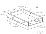
- a release device 28 comprises a rectangular frame 29 comprising four frame strips 29.1 to 29.4, which are connected to each other at corners of the frame 29.
- the lower edge of the frame 29 has a horizontal, flat bearing surface 30 for placing the frame 29 on a horizontal surface.
- the frame has a horizontal, flat support surface 21 for placing a microplate 1.
- the frame strips each have a flat inner surface 32.
- the frame 29 On the outside, the frame 29 has a shoulder 33 running approximately halfway around its height.
- the frame strips 29.1 to 29.4 each have a flat outer surface 34.1, 34.2.
- the frame 29 has two vertical grooves 35.1, 35.2 on the narrow frame strips 29.1, 29.2 on the outside above the shoulder, each vertical groove 35.1, 35.2 being arranged next to a corner of the frame 29.
- the frame 29 encloses a receptacle 36 which is bounded by the inner sides of the frame strips 29.1 to 29.4.
- the frame 29 has a circumferential bevel 37 on the outer upper edge, which forms second sliding surfaces 38.
- the second sliding surfaces 38 form an angle to the vertical.
- the second sliding surfaces 38 are arranged so that they are inclined upward toward each other. As a result, they form an acute angle with an apex above the frame 29.
- the frame strips 29.1 to 29.4 form support projections 39.1 to 39.4 for placing the microplate 1.
- the lid 16 can be placed on the microplate 1, whereby the snap hooks 18 form snap connections at the snap openings 10, at which the horizontal webs 22 engage under the first plate 2 at the lateral edges.
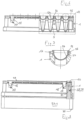
- the sealing elements 24 engage sealingly in the openings 6 of the vessels 5, as shown in the Figs. 6 and 7 shown. In this position, the lid 16 is secured to the microplate 1 by the snap hooks 18.
- the lid 16 is placed onto the microplate 1 from above.
- the snap hooks 18 on the lid 16 engage the snap openings 10 of the microplate 1.
- the snap hooks 18 snap into place behind the edges of the snap openings 10 and hold the lid 16 firmly on the microplate 1.
- the sealing elements 24 form a sealing contact in the upper area against the inside of the vessels 5 and cover them.
- the lid 16 can be removed again by placing the microplate 1 with the snapped-on lid 16 onto the release device 28.
- the outer side and upper side of the release device 28 are designed to be negative to the inner side of the microplate 1. Consequently, the microplate 1 with the snapped-on lid 16 can be placed onto the frame 29 such that the frame 29 engages from below into the circumferential side wall 4 of the microplate and the vessels 5 are immersed in the receptacle 36.
- vertical ribs can engage into the grooves 35.1, 35.2 of the frame 29 for structural stiffening on the inner side of the side wall 4.
- the first sliding surfaces 22 of the snap hooks 18 slide on the second sliding surfaces 38 of the frame 29, thereby bending the snap hooks 18 outwards. This removes the snap connections, allowing the lid 16 to be lifted off the microplate 1 and removed. This can be done in the Fig. 12 shown. The lid 16 can be pushed upwards by the frame 29. After the snap connections are released, the lid 16 can be removed from the microplate 1.
- the placement and snapping of the lid 16 with the microplate 1 as well as the release of the snap connections and removal of the lid 16 from the microplate 1 can be carried out automatically, for example in a laboratory machine or dosing machine.
- the microplate and the lid 16 can be handled by grippers of an automated system (e.g., Epmotion of the applicant).
- an automated system e.g., Epmotion of the applicant.
- the lid 16 can be dimensionally stable and easy to handle, similar to the microplate 1, due to the plastic used and, if necessary, by structural stiffening (ribbing or frame).
- the sealing elements 24 are preferably made of a correspondingly soft or elastic material. This is, for example, a thermoplastic material, e.g., a soft PP, PE, or TPE. Due to the flexibility of the sealing elements 24 and their arrangement in the grid of the vessels 5 of the microplate 1, each sealing element 24 can cover one vessel 5.
- the cover 16 with the sealing elements 24 can consist of several assembled parts or be manufactured by two-component injection molding.
Landscapes
- Health & Medical Sciences (AREA)
- Chemical & Material Sciences (AREA)
- Zoology (AREA)
- Life Sciences & Earth Sciences (AREA)
- Engineering & Computer Science (AREA)
- Bioinformatics & Cheminformatics (AREA)
- Organic Chemistry (AREA)
- Wood Science & Technology (AREA)
- Clinical Laboratory Science (AREA)
- General Health & Medical Sciences (AREA)
- Biomedical Technology (AREA)
- Sustainable Development (AREA)
- Biochemistry (AREA)
- General Engineering & Computer Science (AREA)
- Microbiology (AREA)
- Genetics & Genomics (AREA)
- Biotechnology (AREA)
- Analytical Chemistry (AREA)
- Hematology (AREA)
- Chemical Kinetics & Catalysis (AREA)
- Closures For Containers (AREA)
Claims (15)
- Ensemble, comprenant :• une microplaque (1),• avec une première plaque rectangulaire (2),• une pluralité de récipients (5) disposés en rangées et en colonnes, reliés à la première plaque (2) sur le haut, font saillie vers le bas à partir de la face inférieure de la première plaque et présentent une ouverture (6) sur la face supérieure de la première plaque, et• des ouvertures d'encliquetage (10) sur au moins deux bords latéraux mutuellement opposés de la première plaque (2),• un couvercle (16),• avec une deuxième plaque (17) destinée à être montée sur la face supérieure de la première plaque (2) et à recouvrir les ouvertures (6) des récipients (5) et• des crochets d'encliquetage (18) faisant saillie à partir de la face inférieure de la deuxième plaque (17) sur au moins deux bords latéraux mutuellement opposés de la deuxième plaque (17), dans lequel le couvercle (16) repose sur la face supérieure de la première plaque (2) dans une position de recouvrement avec la deuxième plaque (17), recouvre les ouvertures (6) des récipients (5) et est encliqueté avec les crochets d'encliquetage (18) dans les ouvertures d'encliquetage (10) en formant des liaisons par encliquetage, et• un dispositif de libération (28) destiné à détacher les liaisons par encliquetage entre la microplaque (1) et le couvercle (16),• avec au moins deux saillies d'appui (39.1 - 39.4) dressées vers le haut et au moins un logement (36) entre celles-ci pour le montage d'une microplaque (1) avec au moins deux régions de bords mutuellement opposées de la première plaque (2) sur les saillies d'appui sous engagement des récipients (5) dans l'au moins un logement (36) et• des premières surfaces de glissement (22) sur des côtés intérieurs tournés les uns vers les autres des crochets d'encliquetage (18) sur des bords mutuellement opposés de la première plaque (2) et des deuxièmes surfaces de glissement (38) sur des côtés extérieurs détournés les uns des autres des saillies d'appui (39.1 - 39.4) sur des côtés mutuellement opposés du logement (36), dans lequel les premières surfaces de glissement (22) sont inclinées les unes vers les autres vers le haut sur des côtés intérieurs tournés les uns vers les autres des crochets d'encliquetage (18) et/ou les deuxièmes surfaces de glissement (38) sont inclinées les unes vers les autres vers le haut sur des côtés extérieurs détournés les uns des autres des saillies d'appui (39.1 - 39.4) et les crochets d'encliquetage (18) sont déviés vers l'extérieur et les liaisons par encliquetage sont supprimées lors du montage de la microplaque (1) avec le couvercle (16) encliqueté sur le dispositif de libération (28) par glissement des deuxièmes surfaces de glissement (38) sur les premières surfaces de glissement (22).
- Ensemble selon la revendication 1, dans lequel chaque ouverture d'encliquetage (10) est au moins partiellement disposée dans les deux bords latéraux de la première plaque (2).
- Ensemble selon la revendication 1 ou 2, dans lequel la microplaque (1) comporte une paroi latérale périphérique (4) faisant saillie vers le bas à partir du bord extérieur de la première plaque (2) et chaque ouverture d'encliquetage (10) est au moins partiellement formée dans la région de bord supérieure de la paroi latérale (4).
- Ensemble selon l'une des revendications 1 à 3, dans lequel chaque ouverture d'encliquetage (10) est disposée en une partie (10.1) dans la région de bord latérale de la première plaque (2) et en une autre partie (10.2) dans la région de bord supérieure de la paroi latérale (4).
- Ensemble selon la revendication 4, dans lequel la partie (10.1) de l'ouverture d'encliquetage (10) formée dans la région de bord latérale de la première plaque (2) présente une surface de délimitation supérieure (11.1) s'étendant parallèlement au bord extérieur de la première plaque, laquelle est alignée avec le côté intérieur (13) de la paroi latérale (4) ou décalée vers l'intérieur par rapport à celui-ci, laquelle est adjacente à une surface de délimitation inférieure (12.1) de la partie (10.2) de l'ouverture d'encliquetage (10) dans la région de bord supérieure de la paroi latérale (4).
- Ensemble selon l'une des revendications 1 à 5, dans lequel la microplaque (1) présente respectivement deux ouvertures d'encliquetage (10) sur les deux bords longs de la première plaque (2) et dans lequel le couvercle (16) présente respectivement deux crochets d'encliquetage (18) sur les deux bords longs de la deuxième plaque (17).
- Ensemble selon l'une des revendications 1 à 6, dans lequel la microplaque (1) présente respectivement deux ouvertures d'encliquetage (10) sur les deux bords courts de la première plaque (2) et le couvercle (16) présente respectivement deux crochets d'encliquetage (18) sur les deux bords courts.
- Ensemble selon l'une des revendications 1 à 7, dans lequel chaque crochet d'encliquetage (18) présente une âme verticale (20) et une âme horizontale (21) faisant saillie vers l'intérieur à l'extrémité inférieure de l'âme verticale.
- Ensemble selon la revendication 8, dans lequel l'âme horizontale (21) présente une première surface de glissement (22) à l'extrémité extérieure sur la face inférieure.
- Ensemble selon l'une des revendications 1 à 9, dans lequel la deuxième plaque (17) présente un évidement (23) sur les bords latéraux à côté de la liaison avec le crochet d'encliquetage (18) au-dessus de l'extrémité de crochet du crochet d'encliquetage.
- Ensemble selon l'une des revendications 1 à 10, dans lequel la microplaque (1) et/ou le couvercle (16) présentent au moins un élément d'étanchéité (24), lequel étanchéifie circonférentiellement le bord de chaque ouverture (6) lorsque le couvercle (16) est encliqueté avec la microplaque (1).
- Ensemble selon l'une des revendications 1 à 11, dans lequel le couvercle (16) présente des éléments d'étanchéité (24) disposés en rangées et en colonnes sur la face inférieure de la deuxième plaque, parmi lesquels chacun s'applique sur un bord intérieur de l'une des ouvertures (6) lorsque le couvercle (16) est encliqueté avec la microplaque (1).
- Ensemble selon l'une des revendications 1 à 12, dans lequel la microplaque (1) présente au moins une autre ouverture d'encliquetage (10) entre les bords latéraux dans la première plaque (2), le couvercle (6) présente au moins un autre crochet d'encliquetage (18) faisant saillie vers le bas entre les deux bords latéraux de la deuxième plaque (17), dans lequel l'autre crochet d'encliquetage (18) est introduit dans l'autre ouverture d'encliquetage (10) et encliqueté derrière celle-ci sur la face inférieure de la première plaque (2) lorsque le couvercle (16) s'applique avec la deuxième plaque (17) sur la face supérieure de la première plaque (2) de la microplaque (1), et le dispositif de libération (28) et/ou l'autre crochet d'encliquetage (18) présentent au moins une autre deuxième surface de glissement (38), laquelle est conçue pour glisser sur l'autre première surface de glissement (22) lors du montage de la microplaque (1) avec le couvercle encliqueté (16) sous suppression de la liaison par encliquetage.
- Ensemble selon l'une des revendications 1 à 13, dans lequel le dispositif de libération (28) présente un cadre rectangulaire (29), les saillies d'appui (39.1 - 39.4) sont formées par des bordures de cadre (29.1 - 29.4) du cadre, le logement (36) est délimité par les côtés intérieurs des bordures de cadre (29.1 - 29.4) et la surface d'appui (31) est formée par les surfaces frontales supérieures des bordures de cadre.
- Ensemble selon l'une des revendications 1 à 14, comportant au moins l'une des caractéristiques suivantes :• la microplaque (1) est fabriquée à partir d'une seule ou de plusieurs matières plastiques, son cadre étant si nécessaire constitué d'une autre matière plastique que les récipients (5),• le couvercle (16) est fabriqué à partir d'une seule ou de plusieurs matières plastiques, la deuxième plaque (17) étant si nécessaire constituée d'une autre matière plastique que l'élément d'étanchéité (24),• le dispositif de libération (28) est constitué d'une seule ou de plusieurs matières plastiques, de métal ou d'une combinaison de matière plastique et de métal,• la microplaque (1) et/ou le couvercle (16) et/ou le dispositif de libération (28) sont moulés par injection.
Priority Applications (5)
| Application Number | Priority Date | Filing Date | Title |
|---|---|---|---|
| EP22193653.7A EP4331723B1 (fr) | 2022-09-02 | 2022-09-02 | Ensemble comprenant une microplaque, un couvercle et un dispositif de libération d'une liaison encliquetable entre la microplaque et le couvercle |
| DE112023003679.9T DE112023003679A5 (de) | 2022-09-02 | 2023-08-15 | Set umfassend eine mikroplatte, einen deckel und eine vorrichtung zum lösen einer schnappverbindung zwischen mikroplatte und deckel |
| KR1020257006986A KR20250042833A (ko) | 2022-09-02 | 2023-08-15 | 마이크로플레이트, 뚜껑, 및 마이크로플레이트와 뚜껑 사이의 스냅 연결을 해제하기 위한 장치를 포함하는 세트 |
| CN202380062468.0A CN119816371A (zh) | 2022-09-02 | 2023-08-15 | 包括微孔板、盖子的套件和用于解除微孔板和盖子之间的卡扣连接的装置 |
| PCT/EP2023/072444 WO2024046752A1 (fr) | 2022-09-02 | 2023-08-15 | Ensemble comprenant une microplaque, un couvercle et un dispositif de libération d'une liaison par encliquetage entre la microplaque et le couvercle |
Applications Claiming Priority (1)
| Application Number | Priority Date | Filing Date | Title |
|---|---|---|---|
| EP22193653.7A EP4331723B1 (fr) | 2022-09-02 | 2022-09-02 | Ensemble comprenant une microplaque, un couvercle et un dispositif de libération d'une liaison encliquetable entre la microplaque et le couvercle |
Publications (3)
| Publication Number | Publication Date |
|---|---|
| EP4331723A1 EP4331723A1 (fr) | 2024-03-06 |
| EP4331723C0 EP4331723C0 (fr) | 2025-06-18 |
| EP4331723B1 true EP4331723B1 (fr) | 2025-06-18 |
Family
ID=83191903
Family Applications (1)
| Application Number | Title | Priority Date | Filing Date |
|---|---|---|---|
| EP22193653.7A Active EP4331723B1 (fr) | 2022-09-02 | 2022-09-02 | Ensemble comprenant une microplaque, un couvercle et un dispositif de libération d'une liaison encliquetable entre la microplaque et le couvercle |
Country Status (5)
| Country | Link |
|---|---|
| EP (1) | EP4331723B1 (fr) |
| KR (1) | KR20250042833A (fr) |
| CN (1) | CN119816371A (fr) |
| DE (1) | DE112023003679A5 (fr) |
| WO (1) | WO2024046752A1 (fr) |
Families Citing this family (1)
| Publication number | Priority date | Publication date | Assignee | Title |
|---|---|---|---|---|
| WO2026017533A1 (fr) | 2024-07-16 | 2026-01-22 | Martin Gajewski | Cuve de réaction et agencement de réaction |
Family Cites Families (3)
| Publication number | Priority date | Publication date | Assignee | Title |
|---|---|---|---|---|
| DE10066431B4 (de) | 2000-06-08 | 2013-10-24 | Eppendorf Ag | Mikrotiterplatte |
| WO2002025289A1 (fr) * | 2000-09-18 | 2002-03-28 | I-Card Corporation | Ensemble de micro-coupelles et procede permettant d'enfermer hermetiquement des liquides au moyen de cet ensemble |
| GB201812637D0 (en) * | 2018-08-03 | 2018-09-19 | Randox Laboratories Ltd | PCR cartridge |
-
2022
- 2022-09-02 EP EP22193653.7A patent/EP4331723B1/fr active Active
-
2023
- 2023-08-15 KR KR1020257006986A patent/KR20250042833A/ko active Pending
- 2023-08-15 WO PCT/EP2023/072444 patent/WO2024046752A1/fr not_active Ceased
- 2023-08-15 DE DE112023003679.9T patent/DE112023003679A5/de active Pending
- 2023-08-15 CN CN202380062468.0A patent/CN119816371A/zh active Pending
Also Published As
| Publication number | Publication date |
|---|---|
| EP4331723A1 (fr) | 2024-03-06 |
| KR20250042833A (ko) | 2025-03-27 |
| CN119816371A (zh) | 2025-04-11 |
| EP4331723C0 (fr) | 2025-06-18 |
| WO2024046752A1 (fr) | 2024-03-07 |
| DE112023003679A5 (de) | 2025-07-10 |
Similar Documents
| Publication | Publication Date | Title |
|---|---|---|
| DE3623115C2 (fr) | ||
| DE3137234C2 (de) | Schale für eine Gruppe von Gewebekulturen | |
| DE69831408T2 (de) | Filterplatte | |
| DE69322778T2 (de) | Vakuumplatte | |
| EP2789389B1 (fr) | Dispositif pour stockage et pour fournir des embouts de pipette | |
| DE69013226T2 (de) | Kulturmedium-Verpackung. | |
| DE69917386T2 (de) | Mikroplattenaufbau und Verschluss | |
| EP1161994B2 (fr) | Plaque de microtitrage | |
| EP3576518B1 (fr) | Plateau de culture de plantes, système comportant plateau et godet | |
| DE69902235T2 (de) | Verschlusskappen-array mit blindbohrungen | |
| EP4190452B1 (fr) | Espaceur permettant de maintenir les porte-pipettes empilés à distance les uns des autres | |
| WO2024046752A1 (fr) | Ensemble comprenant une microplaque, un couvercle et un dispositif de libération d'une liaison par encliquetage entre la microplaque et le couvercle | |
| DE202020100361U1 (de) | Variable Transportpalette für Pflanzentöpfe | |
| DE10393523B4 (de) | Behälter zum Lagern einer Vielzahl von Präzision erfordernden Substratscheiben | |
| DE602004011926T2 (de) | Mikroplatte und Deckel zur robotischen Handhabung | |
| EP1417032B1 (fr) | Procede de fabrication d'une couverture de fermeture et couverture de fermeture ainsi fabriquee | |
| EP0671467A2 (fr) | Disque de petri ajustable | |
| DE10038386C2 (de) | Kunststoffbehälter sowie Verfahren und Vorrichtung zu seiner Herstellung | |
| EP0208062B1 (fr) | Réceptacle pour une pluralité d'objets en forme de disque et élément de ce réceptacle | |
| DE202020004181U1 (de) | Set aus einer Anzuchtplatte für Pflanzen und einer Trägerplatte | |
| EP1031276B1 (fr) | Appareil pour la culture de chicorée | |
| DE10066431B4 (de) | Mikrotiterplatte | |
| DE202020000321U1 (de) | Pflanzenzuchtbehältnis für die In-Vitro-Vermehrung | |
| DE10028536B4 (de) | Mikrotiterplatte | |
| EP4327943A1 (fr) | Microplaque |
Legal Events
| Date | Code | Title | Description |
|---|---|---|---|
| PUAI | Public reference made under article 153(3) epc to a published international application that has entered the european phase |
Free format text: ORIGINAL CODE: 0009012 |
|
| STAA | Information on the status of an ep patent application or granted ep patent |
Free format text: STATUS: THE APPLICATION HAS BEEN PUBLISHED |
|
| AK | Designated contracting states |
Kind code of ref document: A1 Designated state(s): AL AT BE BG CH CY CZ DE DK EE ES FI FR GB GR HR HU IE IS IT LI LT LU LV MC MK MT NL NO PL PT RO RS SE SI SK SM TR |
|
| STAA | Information on the status of an ep patent application or granted ep patent |
Free format text: STATUS: REQUEST FOR EXAMINATION WAS MADE |
|
| 17P | Request for examination filed |
Effective date: 20240902 |
|
| RBV | Designated contracting states (corrected) |
Designated state(s): AL AT BE BG CH CY CZ DE DK EE ES FI FR GB GR HR HU IE IS IT LI LT LU LV MC MK MT NL NO PL PT RO RS SE SI SK SM TR |
|
| GRAP | Despatch of communication of intention to grant a patent |
Free format text: ORIGINAL CODE: EPIDOSNIGR1 |
|
| STAA | Information on the status of an ep patent application or granted ep patent |
Free format text: STATUS: GRANT OF PATENT IS INTENDED |
|
| RIC1 | Information provided on ipc code assigned before grant |
Ipc: C12M 1/00 20060101ALI20250130BHEP Ipc: B29C 65/58 20060101ALI20250130BHEP Ipc: C12M 1/32 20060101ALI20250130BHEP Ipc: B01L 3/00 20060101AFI20250130BHEP |
|
| INTG | Intention to grant announced |
Effective date: 20250217 |
|
| GRAS | Grant fee paid |
Free format text: ORIGINAL CODE: EPIDOSNIGR3 |
|
| GRAA | (expected) grant |
Free format text: ORIGINAL CODE: 0009210 |
|
| STAA | Information on the status of an ep patent application or granted ep patent |
Free format text: STATUS: THE PATENT HAS BEEN GRANTED |
|
| AK | Designated contracting states |
Kind code of ref document: B1 Designated state(s): AL AT BE BG CH CY CZ DE DK EE ES FI FR GB GR HR HU IE IS IT LI LT LU LV MC MK MT NL NO PL PT RO RS SE SI SK SM TR |
|
| REG | Reference to a national code |
Ref country code: GB Ref legal event code: FG4D Free format text: NOT ENGLISH |
|
| REG | Reference to a national code |
Ref country code: CH Ref legal event code: EP |
|
| REG | Reference to a national code |
Ref country code: DE Ref legal event code: R096 Ref document number: 502022004303 Country of ref document: DE |
|
| REG | Reference to a national code |
Ref country code: CH Ref legal event code: EP |
|
| REG | Reference to a national code |
Ref country code: IE Ref legal event code: FG4D Free format text: LANGUAGE OF EP DOCUMENT: GERMAN |
|
| U01 | Request for unitary effect filed |
Effective date: 20250618 |
|
| U07 | Unitary effect registered |
Designated state(s): AT BE BG DE DK EE FI FR IT LT LU LV MT NL PT RO SE SI Effective date: 20250626 |
|
| REG | Reference to a national code |
Ref country code: CH Ref legal event code: U11 Free format text: ST27 STATUS EVENT CODE: U-0-0-U10-U11 (AS PROVIDED BY THE NATIONAL OFFICE) Effective date: 20251001 |
|
| PG25 | Lapsed in a contracting state [announced via postgrant information from national office to epo] |
Ref country code: GR Free format text: LAPSE BECAUSE OF FAILURE TO SUBMIT A TRANSLATION OF THE DESCRIPTION OR TO PAY THE FEE WITHIN THE PRESCRIBED TIME-LIMIT Effective date: 20250919 Ref country code: NO Free format text: LAPSE BECAUSE OF FAILURE TO SUBMIT A TRANSLATION OF THE DESCRIPTION OR TO PAY THE FEE WITHIN THE PRESCRIBED TIME-LIMIT Effective date: 20250918 |
|
| PG25 | Lapsed in a contracting state [announced via postgrant information from national office to epo] |
Ref country code: HR Free format text: LAPSE BECAUSE OF FAILURE TO SUBMIT A TRANSLATION OF THE DESCRIPTION OR TO PAY THE FEE WITHIN THE PRESCRIBED TIME-LIMIT Effective date: 20250618 |
|
| PG25 | Lapsed in a contracting state [announced via postgrant information from national office to epo] |
Ref country code: RS Free format text: LAPSE BECAUSE OF FAILURE TO SUBMIT A TRANSLATION OF THE DESCRIPTION OR TO PAY THE FEE WITHIN THE PRESCRIBED TIME-LIMIT Effective date: 20250918 |
|
| U20 | Renewal fee for the european patent with unitary effect paid |
Year of fee payment: 4 Effective date: 20250924 |
|
| PG25 | Lapsed in a contracting state [announced via postgrant information from national office to epo] |
Ref country code: IS Free format text: LAPSE BECAUSE OF FAILURE TO SUBMIT A TRANSLATION OF THE DESCRIPTION OR TO PAY THE FEE WITHIN THE PRESCRIBED TIME-LIMIT Effective date: 20251018 |
|
| PG25 | Lapsed in a contracting state [announced via postgrant information from national office to epo] |
Ref country code: SM Free format text: LAPSE BECAUSE OF FAILURE TO SUBMIT A TRANSLATION OF THE DESCRIPTION OR TO PAY THE FEE WITHIN THE PRESCRIBED TIME-LIMIT Effective date: 20250618 |
|
| PGFP | Annual fee paid to national office [announced via postgrant information from national office to epo] |
Ref country code: CH Payment date: 20251001 Year of fee payment: 4 |
|
| PG25 | Lapsed in a contracting state [announced via postgrant information from national office to epo] |
Ref country code: CZ Free format text: LAPSE BECAUSE OF FAILURE TO SUBMIT A TRANSLATION OF THE DESCRIPTION OR TO PAY THE FEE WITHIN THE PRESCRIBED TIME-LIMIT Effective date: 20250618 |
|
| PG25 | Lapsed in a contracting state [announced via postgrant information from national office to epo] |
Ref country code: PL Free format text: LAPSE BECAUSE OF FAILURE TO SUBMIT A TRANSLATION OF THE DESCRIPTION OR TO PAY THE FEE WITHIN THE PRESCRIBED TIME-LIMIT Effective date: 20250618 |
|
| PG25 | Lapsed in a contracting state [announced via postgrant information from national office to epo] |
Ref country code: SK Free format text: LAPSE BECAUSE OF FAILURE TO SUBMIT A TRANSLATION OF THE DESCRIPTION OR TO PAY THE FEE WITHIN THE PRESCRIBED TIME-LIMIT Effective date: 20250618 |
|
| PG25 | Lapsed in a contracting state [announced via postgrant information from national office to epo] |
Ref country code: ES Free format text: LAPSE BECAUSE OF FAILURE TO SUBMIT A TRANSLATION OF THE DESCRIPTION OR TO PAY THE FEE WITHIN THE PRESCRIBED TIME-LIMIT Effective date: 20250618 |
|
| PLBE | No opposition filed within time limit |
Free format text: ORIGINAL CODE: 0009261 |
|
| STAA | Information on the status of an ep patent application or granted ep patent |
Free format text: STATUS: NO OPPOSITION FILED WITHIN TIME LIMIT |
|
| REG | Reference to a national code |
Ref country code: CH Ref legal event code: L10 Free format text: ST27 STATUS EVENT CODE: U-0-0-L10-L00 (AS PROVIDED BY THE NATIONAL OFFICE) Effective date: 20260430 |
|
| 26N | No opposition filed |
Effective date: 20260319 |
|
| PG25 | Lapsed in a contracting state [announced via postgrant information from national office to epo] |
Ref country code: MC Free format text: LAPSE BECAUSE OF FAILURE TO SUBMIT A TRANSLATION OF THE DESCRIPTION OR TO PAY THE FEE WITHIN THE PRESCRIBED TIME-LIMIT Effective date: 20250618 |
|
| PG25 | Lapsed in a contracting state [announced via postgrant information from national office to epo] |
Ref country code: IE Free format text: LAPSE BECAUSE OF NON-PAYMENT OF DUE FEES Effective date: 20250902 |