EP4332533A1 - Dispositif de mesure de quantité physique - Google Patents
Dispositif de mesure de quantité physique Download PDFInfo
- Publication number
- EP4332533A1 EP4332533A1 EP22795612.5A EP22795612A EP4332533A1 EP 4332533 A1 EP4332533 A1 EP 4332533A1 EP 22795612 A EP22795612 A EP 22795612A EP 4332533 A1 EP4332533 A1 EP 4332533A1
- Authority
- EP
- European Patent Office
- Prior art keywords
- cover member
- casing
- sensor module
- board
- physical quantity
- Prior art date
- Legal status (The legal status is an assumption and is not a legal conclusion. Google has not performed a legal analysis and makes no representation as to the accuracy of the status listed.)
- Pending
Links
Images


Classifications
-
- G—PHYSICS
- G01—MEASURING; TESTING
- G01L—MEASURING FORCE, STRESS, TORQUE, WORK, MECHANICAL POWER, MECHANICAL EFFICIENCY, OR FLUID PRESSURE
- G01L19/00—Details of, or accessories for, apparatus for measuring steady or quasi-steady pressure of a fluent medium insofar as such details or accessories are not special to particular types of pressure gauges
- G01L19/06—Means for preventing overload or deleterious influence of the measured medium on the measuring device or vice versa
-
- G—PHYSICS
- G01—MEASURING; TESTING
- G01L—MEASURING FORCE, STRESS, TORQUE, WORK, MECHANICAL POWER, MECHANICAL EFFICIENCY, OR FLUID PRESSURE
- G01L19/00—Details of, or accessories for, apparatus for measuring steady or quasi-steady pressure of a fluent medium insofar as such details or accessories are not special to particular types of pressure gauges
- G01L19/14—Housings
-
- G—PHYSICS
- G01—MEASURING; TESTING
- G01L—MEASURING FORCE, STRESS, TORQUE, WORK, MECHANICAL POWER, MECHANICAL EFFICIENCY, OR FLUID PRESSURE
- G01L19/00—Details of, or accessories for, apparatus for measuring steady or quasi-steady pressure of a fluent medium insofar as such details or accessories are not special to particular types of pressure gauges
- G01L19/0007—Fluidic connecting means
-
- G—PHYSICS
- G01—MEASURING; TESTING
- G01L—MEASURING FORCE, STRESS, TORQUE, WORK, MECHANICAL POWER, MECHANICAL EFFICIENCY, OR FLUID PRESSURE
- G01L19/00—Details of, or accessories for, apparatus for measuring steady or quasi-steady pressure of a fluent medium insofar as such details or accessories are not special to particular types of pressure gauges
- G01L19/0007—Fluidic connecting means
- G01L19/0038—Fluidic connecting means being part of the housing
-
- G—PHYSICS
- G01—MEASURING; TESTING
- G01L—MEASURING FORCE, STRESS, TORQUE, WORK, MECHANICAL POWER, MECHANICAL EFFICIENCY, OR FLUID PRESSURE
- G01L19/00—Details of, or accessories for, apparatus for measuring steady or quasi-steady pressure of a fluent medium insofar as such details or accessories are not special to particular types of pressure gauges
- G01L19/06—Means for preventing overload or deleterious influence of the measured medium on the measuring device or vice versa
- G01L19/069—Protection against electromagnetic or electrostatic interferences
-
- G—PHYSICS
- G01—MEASURING; TESTING
- G01L—MEASURING FORCE, STRESS, TORQUE, WORK, MECHANICAL POWER, MECHANICAL EFFICIENCY, OR FLUID PRESSURE
- G01L19/00—Details of, or accessories for, apparatus for measuring steady or quasi-steady pressure of a fluent medium insofar as such details or accessories are not special to particular types of pressure gauges
- G01L19/14—Housings
- G01L19/142—Multiple part housings
- G01L19/143—Two part housings
-
- G—PHYSICS
- G01—MEASURING; TESTING
- G01F—MEASURING VOLUME, VOLUME FLOW, MASS FLOW OR LIQUID LEVEL; METERING BY VOLUME
- G01F15/00—Details of, or accessories for, apparatus of groups G01F1/00 - G01F13/00 insofar as such details or appliances are not adapted to particular types of such apparatus
- G01F15/14—Casings, e.g. of special material
Definitions
- the present invention relates to a physical quantity measuring device.
- a physical quantity measuring device including a casing body, a sensor module, and an electronic circuit, in which the sensor module is attached from an outside to an open end of the casing body and the electronic circuit is housed in the casing body.
- Patent Literature 1 a sensor module attached with a sensor tuned to cover an expected measurement range is produced, and the sensor module is attached from an outside to an open end of a casing body, in which an electronic circuit is housed in advance. According to the above arrangement, even after the production process of the casing body is finished, the sensor module attached with the sensor tuned to cover the measurement range can be attached from the outside of the open end of the casing body. A common casing body is thus usable for physical quantity measuring devices of different measurement ranges, reducing the production cost.
- Patent Literature 1 JP 2016-121897 A
- connection pins of the sensor module are guided by a guide member provided for the casing body to an internal terminal on a terminal board. Since the position of the guide member is not determined by the terminal board in the above arrangement, when the position of the internal terminal is misaligned with the guide member, the connection pins of the sensor module may not be appropriately guided to the internal terminal on the terminal board.
- An object of the invention is to provide a physical quantity measuring device capable of securing an electrical connection.
- a physical quantity measuring device includes: a sensor module including a detector configured to detect a physical quantity of a measurement target fluid, a first board for the detector to be attached, and connection pins provided for the first board; a cover member provided with an insertion hole for the connection pins to be inserted, the cover member covering the sensor module; and a second board including a terminal connected with the connection pins, the second board being electrically connected with the first board, in which the cover member is provided with a guide groove portion configured to guide the terminal to the connection pins.
- connection pins provided for the first board of the sensor module are inserted into the insertion hole of the cover member.
- the position of the cover member is determined by the connection pins.
- the cover member, whose position is determined by the connection pins, is provided with the guide groove portion to guide the terminal of the second board to the connection pins.
- the position of the terminal of the second board is thus determined by the connection pins via the guide groove portion of the cover member. Accordingly, since the connection pins, the guide groove portion, and the terminal are not misaligned, the terminal can be securely guided to the connection pins by the guide groove portion.
- the physical quantity measuring device further includes: a sealing member interposed between the cover member and the sensor module, in which the cover member is provided with a cutout at a position corresponding to the sealing member.
- the sealing member is interposed between the cover member and the sensor module. At this time, the position of the sealing member can be checked through the cutout, which is formed in the cover member at the position corresponding to the sealing member. This inhibits misalignment of the sealing member.
- the physical quantity measuring device further includes a casing that houses the sensor module, the cover member, and the second board, in which the cover member includes a cover member body covering the sensor module and a plurality of claws extending from the cover member body to protrude in a direction orthogonal to the cover member body, and a plurality of engagement grooves are provided in an inner circumferential surface of the casing, the engagement grooves being respectively engaged with the claws.
- the cover member includes the cover member body covering the sensor module and the plurality of claws extending from the cover member body to protrude in the direction orthogonal to the cover member body. Further, the casing to house the sensor module and the cover member is provided with the plurality of engagement grooves in an inner circumferential surface thereof, the engagement grooves being respectively engaged with the claws. The cover member can thus be fixed by engaging the claws with the engagement grooves formed in the inner circumferential surface of the casing. Accordingly, the cover member can be securely fixed.
- the cover member body is rectangular in a plan view and the claws include a first claw and a second claw provided opposite the first claw across the cover member body.
- the first claw and the second claw are provided on opposite sides across the cover member body having a rectangular profile in a plan view.
- the cover member is thus engaged with and fixed to the casing at both sides of the cover member body. Accordingly, the cover member can be further securely fixed.
- a physical quantity measuring device 1 according to an exemplary embodiment of the invention will be described below with reference to the attached drawings.
- Fig. 1 is a perspective view of an outline of the physical quantity measuring device 1 according to the present exemplary embodiment.
- Fig. 2 is another perspective view of the outline of the physical quantity measuring device 1 viewed in a direction different from the direction in Fig. 1 .
- Fig. 3 is an exploded perspective view of the outline of the physical quantity measuring device 1.
- Fig. 4 is another exploded perspective view of the physical quantity measuring device 1 viewed in a direction different from the direction in Fig. 3 .
- Fig. 5 is a cross-sectional view of the outline of the physical quantity measuring device 1.
- the physical quantity measuring device 1 of the present exemplary embodiment is a differential pressure sensor, more specifically, a small-sized digital micro-differential pressure sensor.
- the physical quantity measuring device 1 includes a first casing 2, a second casing 3, a circuit board 4, a sensor module 5, a base member 61, ports 62, and a cover member 7.
- the first casing 2 is a hollow rectangular component configured to house the sensor module 5 and the like.
- the first casing 2 is an exemplary casing of the invention.
- the first casing 2 includes a first casing body 21 and a fitting portion 22.
- the first casing body 21 is configured to house the sensor module 5 and the like therein.
- the first casing body 21 is provided with first supports 211 and contact portions 212.
- the first supports 211 are columnar components provided at four respective corners of the first casing body 21 in a manner protruding toward the second casing 3. Specifically, four first supports 211 are provided integrally with the first casing body 21 in the present exemplary embodiment.
- the contact portions 212 are respectively provided inside the first supports 211 at diagonal positions of the first casing body 21. In the present exemplary embodiment, the contact portions 212 are provided at two positions on the first casing body 21. Each of the contact portions 212 is in contact with one of later-described elastic support members 415.
- an opening 214 is provided in the first casing body 21 at a position corresponding to an external terminal 413 provided on a later-described relay board 41.
- the external terminal 413 is thus configured to be exposed to an outside of the first casing 2.
- a support structure 215 that contacts and supports the later-described relay board 41 is provided on an inner side of the first casing body 21.
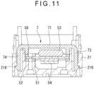
- engagement grooves 216 are formed in an inner circumferential surface of the first casing body 21 (see, Fig. 11 ).
- the fitting portion 22 is a thinned portion at an end of the first casing body 21.
- the fitting portion 22 is configured to be inserted into a later-described second casing body 31 of the second casing 3 and be fitted to an inner circumference of the second casing body 31.
- the second casing 3 is a hollow rectangular component to house a later-described display board 42 of the circuit board 4 and the like.
- the second casing 3 which includes the second casing body 31 and a panel sheet 32, is fitted to the above-described first casing 2.
- the second casing 3 is attached to the first casing 2 in the present exemplary embodiment.
- the second casing body 31 is configured to house the display board 42 and the like therein.
- the second casing body 31 is provided with second supports 311, an interior wall portion 312, and protrusions 313. Further, the second casing body 31 is configured such that an exterior surface thereof is flush with an exterior surface of the first casing body 21 when being attached to the first casing 2.
- the panel sheet 32 is attached to an outer bottom surface (i.e. a front surface) of the second casing body 31.
- the panel sheet 32 may include an indication of a model number, specification, and the like of the physical quantity measuring device 1.
- the second supports 311 are columnar components provided near four corners of the second casing body 31 in a manner protruding toward the first casing 2. Specifically, four second supports 311 are provided integrally with the second casing body 31 in the present exemplary embodiment. In the present exemplary embodiment, the second supports 311 are configured to be located inward with respect to the above-described first supports 211 of the first casing 2.
- the circuit board 4 includes the relay board 41 and the display board 42 facing each other.
- the relay board 41 is housed in the first casing body 21.
- first cutouts 411 are provided in the relay board 41 at positions corresponding to the above-described first supports 211 (i.e., at four corners) of the first casing body 21.
- the first cutouts 411 are provided at four positions in the relay board 41.
- Each of the first supports 211 is thus inserted through the corresponding one of the first cutouts 411 when the relay board 41 is housed in the first casing body 21.
- the position of the relay board 41 is thus determined by the first supports 211 of the first casing 2.
- the relay board 41 is held between the second supports 311 inserted through later-described second cutouts 421 of the display board 42 and the support structure 215 of the first casing 2. As described above, the relay board 41 in the present exemplary embodiment, which is held between the first casing 2 and the second casing 3, is positioned and supported by the first casing 2. Accordingly, the relay board 41 can be securely supported.
- the relay board 41 is provided with a connector receiver 412, the external terminal 413, an internal terminal 414, and elastic support members 415.
- the connector receiver 412 is disposed on a surface of the relay board 41 facing the display board 42.
- the connector receiver 412 is connectable with a later-described connector 422 of the display board 42.
- the relay board 41 and the display board 42 are electrically connected by connecting the connector receiver 412 and the connector 422.
- the external terminal 413 is disposed at a position corresponding to the opening 214 of the first casing body 21 to be exposed to an outside of the first casing body 21 through the opening 214.
- the external terminal 413 is thus connectable with wiring for external output, wiring for a power source, and the like.
- the external terminal 413 is provided with an external output terminal and a power source terminal.
- the internal terminal 414 which is disposed at a position corresponding to later-described connection pins 55 of the sensor module 5, is connectable with the connection pins 55.
- the relay board 41 and the sensor module 5 are electrically connected by connecting the connection pins 55 and the internal terminal 414.
- the relay board 41 and the display board 42 are electrically connected with the sensor module 5 in the present exemplary embodiment.
- the internal terminal 414 is an exemplary terminal of the invention.
- the elastic support member 415 is a metallic spring member having a Z-shaped cross section.
- the elastic support members 415 are interposed, at diagonal positions of the first casing body 21, between the contact portions 212 of the first casing body 21 and the later-described relay board 41 of the circuit board 4.
- the display board 42 is housed in the second casing body 31.
- the second cutouts 421 are provided in the display board 42 at positions corresponding to the above-described second supports 311 (i.e. near four corners) of the second casing body 31.
- the second cutouts 421 are provided at four positions in the display board 42.
- Each of the second supports 311 is thus inserted through the corresponding one of the second cutouts 421 when the display board 42 is housed in the second casing body 31.
- the position of the display board 42 is thus determined by the second supports 311 of the second casing 3.
- the display board 42 is held between the first supports 211 inserted through the first cutouts 411 of the relay board 41 and the protrusions 313 of the second casing 3.
- the display board 42 in the present exemplary embodiment which is held between the first casing 2 and the second casing 3, is positioned and supported by the second casing 3. Accordingly, the display board 42 can be securely supported.
- the display board 42 is provided with the connector 422.
- the connector 422 which is disposed at a position corresponding to the connector receiver 412 of the relay board 41, is connectable with the connector receiver 412.
- Fig. 6 is an exploded perspective view of an outline of the sensor module 5.
- Fig. 7 is another exploded perspective view of the outline of the sensor module 5 viewed in a direction different from the direction in Fig. 6 .
- the sensor module 5 includes a sensor printed circuit board (PCB) 51, a first gasket 52, an electronic component 53, a detector 54, the connection pins 55, and a second gasket 56.
- PCB sensor printed circuit board
- the sensor PCB 51 is a board for components such as the electronic component 53 and the detector 54 to be attached.
- the sensor PCB 51 is disposed to face the above-described relay board 41.
- the surface of the sensor PCB 51 facing the relay board 41 is covered with the cover member 7.
- the sensor PCB 51 is an exemplary first board of the invention.
- the first gasket 52 which is an annular rectangle component made of rubber or a resin member, is interposed between the first casing body 21 and the sensor PCB 51.
- the first gasket 52 is disposed to surround the detector 54. The space for the detector 54 of the sensor module 5 to be provided is thus sealed.
- the electronic component 53 which is disposed on a surface of the sensor PCB 51 facing the relay board 41, is covered with the cover member 7.
- the electronic component 53 includes a signal converter to convert/tune signals outputted from the detector 54 and the like.
- the detector 54 is configured to detect a pressure of a measurement target fluid introduced through ports 62 and output the signals according to the pressure to the electronic component 53.
- connection pins 55 which are disposed at a position corresponding to the internal terminal 414 of the relay board 41, are connectable with the internal terminal 414.
- the second gasket 56 which is an annular rectangle component made of rubber or a resin member, is interposed between the cover member 7 and the sensor PCB 51.
- the second gasket 56 is disposed to surround the electronic component 53. The space for the electronic component 53 of the sensor module 5 to be provided is thus sealed.
- the base member 61 is a plate-shaped component attached to a rear side of the first casing body 21.
- the base member 61 has two holes (not illustrated in the drawings) to which two ports 62 are attached.
- a filter (not illustrated in the drawings) is inserted at a rear side of the base member 61 (i.e. a side near the first casing body 21).
- the ports 62 are cylindrical components through which the measurement target fluid is introduced.
- the measurement target fluid is thus introduced into a space inside the first casing body 21, in which the detector 54 is disposed, through the ports 62 and the filter.
- two ports 62 are attached to the base member 61 in the present exemplary embodiment.
- the physical quantity measuring device 1 of the present exemplary embodiment is a differential-pressure sensor configured to detect a differential pressure of the measurement target fluid introduced into the two ports 62.
- the invention is not limited to the above configuration.
- no filter may be provided at the rear side of the base member 61.
- Fig. 8 is an exploded perspective view of the sensor module 5 and a cover member 7 with a part thereof being sectioned.
- Fig. 9 is a perspective view of the sensor module 5 and the cover member 7 with a part thereof being enlarged.
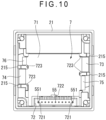
- Fig. 10 is a plan view of an outline of the first casing 2 and the cover member 7.
- Fig. 11 is a cross-sectional view of the first casing 2, the cover member 7, and the sensor module 5.
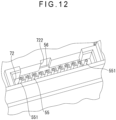
- Fig. 12 is a perspective view of the sensor module 5 and the cover member 7 with a part thereof being enlarged.
- the cover member 7, which is a component covering the sensor module 5, is made of a resin member or metal. Specifically, the cover member 7 covers a surface of the sensor PCB 51 provided with the electronic component 53.
- the cover member 7 includes a cover member body 71, a guide groove portion 72, a first claw 73, a second claw 74, a first contact portion 75, and a second contact portion 76.
- the cover member body 71 covers the surface of the sensor PCB 51 provided with the electronic component 53.
- the cover member body 71 is rectangular in a plan view.
- the guide groove portion 72 is formed at a position corresponding to the connection pins 55.
- the guide groove portion 72 is configured to serve as a guide groove for guiding the internal terminal 414 to the connection pins 55.
- the guide groove portion 72 includes two insertion holes 721 into which two terminal connection pins 551, which are disposed at ends of the linearly arranged connection pins 55, are inserted.
- the terminal connection pins 551 are inserted into the respective insertion holes 721 to enable the sensor module 5 to determine the position of the cover member 7.
- the guide groove portion 72 of the present exemplary embodiment is provided with a cutout 722 at a position corresponding to the above-described second gasket 56.
- the position of the second gasket 56 can thus be seen through the cutout 722 (see, Fig. 12 ). This inhibits misalignment of the second gasket 56 that may otherwise be caused when the second gasket 56 is provided between the sensor PCB 51 and the cover member 7.
- the second gasket 56 is an exemplary sealing member of the invention.
- the first claw 73 extends from the cover member body 71 to protrude in a direction orthogonal to the cover member body 71.
- An end of the first claw 73 is bent to be L-shaped in a cross-sectional view.
- the second claw 74 extends from the cover member body 71 to protrude in the direction orthogonal to the cover member body 71. More specifically, the second claw 74 is provided opposite the first claw 73 across the cover member body 71. An end of the second claw 74 is bent to be L-shaped in a cross-sectional view.
- the cover member body 71 includes grooves 723 provided on both sides of each of the first claw 73 and the second claw 74.
- the first contact portion 75 extends from the cover member body 71 to protrude in the direction orthogonal to the cover member body 71.
- the first contact portion 75 which is disposed near the first claw 73, is capable of being in contact with an inner circumferential surface of the first casing 2.
- the second contact portion 76 extends from the cover member body 71 to protrude in the direction orthogonal to the cover member body 71.
- the second contact portion 76 which is disposed near the second claw 74, is capable of being in contact with the inner circumferential surface of the first casing 2.
- connection pins 55 and the internal terminal 414 are connected will be described below.
- the internal terminal 414 of the relay board 41 is guided by the guide groove portion 72 of the cover member 7 to be disposed at the position corresponding to the connection pins 55, as illustrated in Fig. 9 .
- the internal terminal 414 is thus securely guided to a position capable of being connected with the connection pins 55.
- the connection pins 55, the guide groove portion 72, and the internal terminal 414 are not misaligned. Accordingly, the internal terminal 414 can be securely guided to the connection pins 55 by the guide groove portion 72.
- the cover member 7 when the cover member 7 is installed to cover the sensor module 5, the first claw 73 and the second claw 74 are engaged with the engagement grooves 216 formed in the inner circumferential surface of the first casing body 21.
- the cover member 7 is thus fixed to the first casing 2.
- the cover member 7 since the first claw 73 and the second claw 74 are provided on opposite sides across the cover member body 71 having a rectangular profile in a plan view, the cover member 7 is engaged with and fixed to the first casing 2 at both sides of the cover member body 71. Accordingly, the cover member 7 can be further securely fixed.
- the first claw 73 and the second claw 74 are guided by the support structure 215 and the grooves 723 to be led to the engagement grooves 216. This facilitates the attachment of the cover member 7.
- the cover member 7 when the cover member 7 is fixed to the first casing 2 in the present exemplary embodiment, the first contact portion 75 and the second contact portion 76 are brought into contact with an outside of a wall surface of the first casing body 21 for housing the sensor module 5.
- the position of the cover member 7 is determined by the first claw 73, the second claw 74, the first contact portion 75, and the second contact portion 76 in the present exemplary embodiment. Accordingly, the position of the cover member 7 can be kept from being displaced by, for instance, receiving an impact or the like.
- the elastic support members 415 brought into contact with the contact portions 212 of the first casing 2 are spring components having a Z-shaped cross section.
- the invention is not limited thereto.
- the elastic support members are in any desired form (e.g. a coil spring component) as long as being capable of biasing the first board toward the second casing. Further, the scope of the invention encompasses an arrangement without any elastic support member.
- the relay board 41 is housed in the first casing 2.
- the invention is not limited thereto.
- the relay board is optionally housed in the second casing.
- the display board 42 is housed in the second casing 3 in the above exemplary embodiment.
- the invention is not limited thereto.
- the display board is optionally housed in the first casing.
- first supports 211 and the second supports 311 are columnar components.
- the invention is not limited thereto.
- the first and second supports are optionally in a form of rectangular columns or hollow pipe-shaped components.
- first supports 211 and four second supports 311 are provided.
- the invention is not limited thereto.
- the number of the first supports and the second supports may each be five or more or three or less. It is only necessary that a plurality of first supports and a plurality of second supports are provided.
- the physical quantity measuring device 1 is a differential-pressure sensor configured to detect a differential pressure of the measurement target fluid introduced into the two ports 62.
- the invention is not limited thereto.
- the physical quantity measuring device is optionally a pressure sensor provided with a single port and configured to detect a pressure of the measurement target fluid introduced into the port or a temperature sensor configured to detect a temperature of the measurement target fluid. It is only necessary for the physical quantity measuring device to be configured to detect a physical quantity of the measurement target fluid.
- the relay board 41 is provided with the first cutouts 411 at four corners.
- the invention is not limited thereto.
- a plurality of first cutouts are optionally provided near a central part of the first board so that the first supports of the first casing may be inserted through the first cutouts.
- the position and the number of the first cutouts in the first board are designed as desired.
- the display board 42 is provided with the second cutouts 421 near four corners in the above exemplary embodiment.
- the invention is not limited thereto.
- a plurality of second cutouts are optionally provided near a central part of the second board so that the second supports of the second casing may be inserted through the second cutouts.
- the position and the number of the second cutouts in the second board are designed as desired.
- the cutout 722 is provided in the guide groove portion 72.
- the invention is not limited thereto.
- the cutout is optionally provided in the cover member body as long as being provided at a position corresponding to the second gasket.
- the scope of the invention encompasses an arrangement without any cutout in the cover member.
- the cover member 7 is fixed to the first casing 2 by engaging the first claw 73 and the second claw 74 with the engagement grooves 216 of the first casing body 21.
- the invention is not limited thereto.
- the cover member is optionally fixed on the first casing by a fastener such as a bolt.
- 1...physical quantity measuring device 2...first casing, 3...second casing, 4...circuit board, 5...sensor module, 7...cover member, 21...first casing body, 22...fitting portion, 31...second casing body, 32...panel sheet, 41...relay board (second board), 42...display board, 51...sensor PCB (first board), 52...first gasket, 53...electronic component, 54...detector, 55...connection pin, 56...second gasket (sealing member), 61...base member, 62...port, 71...cover member body, 72...guide groove portion, 73...first claw, 74...second claw, 75...first contact portion, 76...second contact portion, 211...firstsupport, 212...contact portion, 214...opening, 215...support structure, 216...
- engagement groove 311...second support, 312...interior wall portion, 313...protrusion, 411...first cutout, 412...connector receiver, 413...external terminal, 414...internal terminal (terminal), 415...elastic support member, 421...second cutout, 422...connector, 551...terminal connection pin, 721...insertion hole, 722...cutout, 723...groove
Landscapes
- Physics & Mathematics (AREA)
- General Physics & Mathematics (AREA)
- Electromagnetism (AREA)
- Measuring Fluid Pressure (AREA)
Applications Claiming Priority (2)
| Application Number | Priority Date | Filing Date | Title |
|---|---|---|---|
| JP2021075984A JP7440456B2 (ja) | 2021-04-28 | 2021-04-28 | 物理量測定装置 |
| PCT/JP2022/017983 WO2022230699A1 (fr) | 2021-04-28 | 2022-04-18 | Dispositif de mesure de quantité physique |
Publications (2)
| Publication Number | Publication Date |
|---|---|
| EP4332533A1 true EP4332533A1 (fr) | 2024-03-06 |
| EP4332533A4 EP4332533A4 (fr) | 2025-04-23 |
Family
ID=83847019
Family Applications (1)
| Application Number | Title | Priority Date | Filing Date |
|---|---|---|---|
| EP22795612.5A Pending EP4332533A4 (fr) | 2021-04-28 | 2022-04-18 | Dispositif de mesure de quantité physique |
Country Status (4)
| Country | Link |
|---|---|
| EP (1) | EP4332533A4 (fr) |
| JP (1) | JP7440456B2 (fr) |
| KR (1) | KR20230172583A (fr) |
| WO (1) | WO2022230699A1 (fr) |
Families Citing this family (1)
| Publication number | Priority date | Publication date | Assignee | Title |
|---|---|---|---|---|
| KR102659339B1 (ko) * | 2020-12-29 | 2024-04-19 | 한국기초과학지원연구원 | 강자성 공명 및 역스핀홀 전압측정 시스템용 동일평면 도파관 및 그를 이용한 프로우브 인서트 |
Family Cites Families (14)
| Publication number | Priority date | Publication date | Assignee | Title |
|---|---|---|---|---|
| US5317921A (en) * | 1992-05-05 | 1994-06-07 | Maclean Fogg Company | Resistive strain gauge pressure sensor |
| JPH0821775A (ja) * | 1994-07-08 | 1996-01-23 | Fuji Koki Seisakusho:Kk | 圧力センサ |
| JPH0843233A (ja) * | 1994-07-29 | 1996-02-16 | Matsushita Electric Works Ltd | 圧力センサ |
| JPH1123400A (ja) * | 1997-05-09 | 1999-01-29 | Fuji Koki Corp | 圧力センサ |
| JP4281178B2 (ja) * | 1999-10-06 | 2009-06-17 | 株式会社デンソー | 半導体圧力センサ |
| JP2002107246A (ja) * | 2000-09-29 | 2002-04-10 | Matsushita Electric Works Ltd | 半導体センサ |
| JP4756685B2 (ja) * | 2005-06-21 | 2011-08-24 | 内山工業株式会社 | ガスケットの組付構造 |
| JP4652962B2 (ja) * | 2005-12-05 | 2011-03-16 | 長野計器株式会社 | センサ装置 |
| ITTO20080484A1 (it) * | 2008-06-19 | 2009-12-20 | Eltek Spa | Dispositivo sensore di pressione |
| ITTO20080485A1 (it) * | 2008-06-19 | 2009-12-20 | Eltek Spa | Dispositivo sensore di pressione |
| DK2236998T3 (da) * | 2009-04-02 | 2012-04-16 | Kamstrup As | Forbrugsmåler med roterbart display |
| JP5761126B2 (ja) * | 2012-05-31 | 2015-08-12 | 日本精機株式会社 | 圧力検出装置 |
| JP6283307B2 (ja) | 2014-12-24 | 2018-02-21 | 長野計器株式会社 | 物理量測定装置 |
| JP7192687B2 (ja) * | 2019-07-12 | 2022-12-20 | 株式会社デンソー | センサ装置 |
-
2021
- 2021-04-28 JP JP2021075984A patent/JP7440456B2/ja active Active
-
2022
- 2022-04-18 WO PCT/JP2022/017983 patent/WO2022230699A1/fr not_active Ceased
- 2022-04-18 EP EP22795612.5A patent/EP4332533A4/fr active Pending
- 2022-04-18 KR KR1020237039998A patent/KR20230172583A/ko active Pending
Also Published As
| Publication number | Publication date |
|---|---|
| WO2022230699A1 (fr) | 2022-11-03 |
| EP4332533A4 (fr) | 2025-04-23 |
| JP2022170094A (ja) | 2022-11-10 |
| KR20230172583A (ko) | 2023-12-22 |
| JP7440456B2 (ja) | 2024-02-28 |
Similar Documents
| Publication | Publication Date | Title |
|---|---|---|
| US10010006B2 (en) | Electronic control device and method of manufacturing electronic control device | |
| US6368130B1 (en) | Connector adapted to absorb a positional misalignment | |
| EP4332533A1 (fr) | Dispositif de mesure de quantité physique | |
| US8111167B2 (en) | Level indicator and process for assembling a level indicator | |
| TW201602539A (zh) | 物理量測定裝置及其製造方法 | |
| US10006826B2 (en) | Semiconductor pressure sensor device | |
| KR20230049041A (ko) | 인발 저항을 증가시키기 위한 케이블 보호 커버 | |
| CN118234123A (zh) | 电路板组件、传感器、热管理系统和车辆 | |
| CN118225166A (zh) | 传感器、热管理系统和车辆 | |
| CN217930570U (zh) | 一种温感模组及厨房电器 | |
| KR100259694B1 (ko) | 압력센서 | |
| CN222601540U (zh) | 连接器、传感器、热管理系统和车辆 | |
| EP4332532A1 (fr) | Dispositif de mesure de quantité physique | |
| JP2002071499A (ja) | 圧力センサ | |
| EP4207501A1 (fr) | Connecteur et ensemble connecteur | |
| CN222850092U (zh) | 温度压力传感器的壳体、温度压力传感器和车辆 | |
| JP2583978Y2 (ja) | 回路基板の収納ハウジングの構造 | |
| US4627286A (en) | Pressure or pressure difference measuring instrument | |
| JP2018059765A (ja) | 電子式電力量計を収容するための収容ケース及び収容ケースと電子式電力量計とを備える電子式電力量計ユニット | |
| CN219498373U (zh) | 一种连接器模组及电子设备 | |
| CN221612295U (zh) | 数字压力表 | |
| JP7472280B2 (ja) | 電流センサ | |
| US20220399674A1 (en) | Sealing Installation Device and Connector Assembly | |
| CN222380894U (zh) | 一种连接器胶芯 | |
| KR102870408B1 (ko) | 압력 센서 |
Legal Events
| Date | Code | Title | Description |
|---|---|---|---|
| STAA | Information on the status of an ep patent application or granted ep patent |
Free format text: STATUS: THE INTERNATIONAL PUBLICATION HAS BEEN MADE |
|
| PUAI | Public reference made under article 153(3) epc to a published international application that has entered the european phase |
Free format text: ORIGINAL CODE: 0009012 |
|
| STAA | Information on the status of an ep patent application or granted ep patent |
Free format text: STATUS: REQUEST FOR EXAMINATION WAS MADE |
|
| 17P | Request for examination filed |
Effective date: 20231124 |
|
| AK | Designated contracting states |
Kind code of ref document: A1 Designated state(s): AL AT BE BG CH CY CZ DE DK EE ES FI FR GB GR HR HU IE IS IT LI LT LU LV MC MK MT NL NO PL PT RO RS SE SI SK SM TR |
|
| DAV | Request for validation of the european patent (deleted) | ||
| DAX | Request for extension of the european patent (deleted) | ||
| A4 | Supplementary search report drawn up and despatched |
Effective date: 20250325 |
|
| RIC1 | Information provided on ipc code assigned before grant |
Ipc: G01F 15/14 20060101ALI20250319BHEP Ipc: G01L 19/06 20060101ALI20250319BHEP Ipc: G01L 19/00 20060101ALI20250319BHEP Ipc: G01L 19/14 20060101AFI20250319BHEP |