EP4342599A1 - Procédé de laminage de billes - Google Patents
Procédé de laminage de billes Download PDFInfo
- Publication number
- EP4342599A1 EP4342599A1 EP23193049.6A EP23193049A EP4342599A1 EP 4342599 A1 EP4342599 A1 EP 4342599A1 EP 23193049 A EP23193049 A EP 23193049A EP 4342599 A1 EP4342599 A1 EP 4342599A1
- Authority
- EP
- European Patent Office
- Prior art keywords
- stand
- blank
- grooved rolls
- rolls
- diameter
- Prior art date
- Legal status (The legal status is an assumption and is not a legal conclusion. Google has not performed a legal analysis and makes no representation as to the accuracy of the status listed.)
- Pending
Links
- 238000005096 rolling process Methods 0.000 title claims abstract description 91
- 238000000034 method Methods 0.000 title claims abstract description 25
- QNRATNLHPGXHMA-XZHTYLCXSA-N (r)-(6-ethoxyquinolin-4-yl)-[(2s,4s,5r)-5-ethyl-1-azabicyclo[2.2.2]octan-2-yl]methanol;hydrochloride Chemical compound Cl.C([C@H]([C@H](C1)CC)C2)CN1[C@@H]2[C@H](O)C1=CC=NC2=CC=C(OCC)C=C21 QNRATNLHPGXHMA-XZHTYLCXSA-N 0.000 claims description 6
- 238000005242 forging Methods 0.000 description 10
- 238000007493 shaping process Methods 0.000 description 7
- 238000004519 manufacturing process Methods 0.000 description 4
- 239000000463 material Substances 0.000 description 4
- 238000005266 casting Methods 0.000 description 3
- 238000005516 engineering process Methods 0.000 description 2
- 229910052751 metal Inorganic materials 0.000 description 2
- 239000002184 metal Substances 0.000 description 2
- OKTJSMMVPCPJKN-UHFFFAOYSA-N Carbon Chemical compound [C] OKTJSMMVPCPJKN-UHFFFAOYSA-N 0.000 description 1
- 229910001208 Crucible steel Inorganic materials 0.000 description 1
- PWHULOQIROXLJO-UHFFFAOYSA-N Manganese Chemical compound [Mn] PWHULOQIROXLJO-UHFFFAOYSA-N 0.000 description 1
- 229910000831 Steel Inorganic materials 0.000 description 1
- 230000015572 biosynthetic process Effects 0.000 description 1
- 229910052799 carbon Inorganic materials 0.000 description 1
- 230000000694 effects Effects 0.000 description 1
- 229910052748 manganese Inorganic materials 0.000 description 1
- 239000011572 manganese Substances 0.000 description 1
- 150000002739 metals Chemical class 0.000 description 1
- 230000035945 sensitivity Effects 0.000 description 1
- 239000010959 steel Substances 0.000 description 1
Images



Classifications
-
- B—PERFORMING OPERATIONS; TRANSPORTING
- B21—MECHANICAL METAL-WORKING WITHOUT ESSENTIALLY REMOVING MATERIAL; PUNCHING METAL
- B21B—ROLLING OF METAL
- B21B1/00—Metal-rolling methods or mills for making semi-finished products of solid or profiled cross-section; Sequence of operations in milling trains; Layout of rolling-mill plant, e.g. grouping of stands; Succession of passes or of sectional pass alternations
- B21B1/08—Metal-rolling methods or mills for making semi-finished products of solid or profiled cross-section; Sequence of operations in milling trains; Layout of rolling-mill plant, e.g. grouping of stands; Succession of passes or of sectional pass alternations for rolling structural sections, i.e. work of special cross-section, e.g. angle steel
- B21B1/085—Rail sections
-
- B—PERFORMING OPERATIONS; TRANSPORTING
- B21—MECHANICAL METAL-WORKING WITHOUT ESSENTIALLY REMOVING MATERIAL; PUNCHING METAL
- B21K—MAKING FORGED OR PRESSED METAL PRODUCTS, e.g. HORSE-SHOES, RIVETS, BOLTS OR WHEELS
- B21K1/00—Making machine elements
- B21K1/02—Making machine elements balls, rolls, or rollers, e.g. for bearings
-
- B—PERFORMING OPERATIONS; TRANSPORTING
- B21—MECHANICAL METAL-WORKING WITHOUT ESSENTIALLY REMOVING MATERIAL; PUNCHING METAL
- B21B—ROLLING OF METAL
- B21B1/00—Metal-rolling methods or mills for making semi-finished products of solid or profiled cross-section; Sequence of operations in milling trains; Layout of rolling-mill plant, e.g. grouping of stands; Succession of passes or of sectional pass alternations
- B21B1/08—Metal-rolling methods or mills for making semi-finished products of solid or profiled cross-section; Sequence of operations in milling trains; Layout of rolling-mill plant, e.g. grouping of stands; Succession of passes or of sectional pass alternations for rolling structural sections, i.e. work of special cross-section, e.g. angle steel
- B21B1/085—Rail sections
- B21B1/0855—Rerolling or processing worn or discarded rail sections
-
- B—PERFORMING OPERATIONS; TRANSPORTING
- B21—MECHANICAL METAL-WORKING WITHOUT ESSENTIALLY REMOVING MATERIAL; PUNCHING METAL
- B21B—ROLLING OF METAL
- B21B13/00—Metal-rolling stands, i.e. an assembly composed of a stand frame, rolls, and accessories
- B21B13/005—Cantilevered roll stands
-
- B—PERFORMING OPERATIONS; TRANSPORTING
- B21—MECHANICAL METAL-WORKING WITHOUT ESSENTIALLY REMOVING MATERIAL; PUNCHING METAL
- B21B—ROLLING OF METAL
- B21B13/00—Metal-rolling stands, i.e. an assembly composed of a stand frame, rolls, and accessories
- B21B13/02—Metal-rolling stands, i.e. an assembly composed of a stand frame, rolls, and accessories with axes of rolls arranged horizontally
-
- B—PERFORMING OPERATIONS; TRANSPORTING
- B21—MECHANICAL METAL-WORKING WITHOUT ESSENTIALLY REMOVING MATERIAL; PUNCHING METAL
- B21B—ROLLING OF METAL
- B21B37/00—Control devices or methods specially adapted for metal-rolling mills or the work produced thereby
- B21B37/58—Roll-force control; Roll-gap control
-
- B—PERFORMING OPERATIONS; TRANSPORTING
- B21—MECHANICAL METAL-WORKING WITHOUT ESSENTIALLY REMOVING MATERIAL; PUNCHING METAL
- B21H—MAKING PARTICULAR METAL OBJECTS BY ROLLING, e.g. SCREWS, WHEELS, RINGS, BARRELS, BALLS
- B21H1/00—Making articles shaped as bodies of revolution
- B21H1/14—Making articles shaped as bodies of revolution balls, rollers, cone rollers, or like bodies
Definitions
- the invention relates to a method of rolling balls, especially from feet of scrap railway rails.
- a number of methods for manufacturing balls intended for grinding media for ball mills have been known and used so far.
- the most common ones include casting, die forging and rolling.
- the balls are cast from cast steel which is cast into permanent moulds made of metal, the so-called casting dies.
- Die forging of balls is typically carried out on friction presses, with the use of billets in the form of bars made of steel with increased carbon and manganese content.
- the flash is trimmed on eccentric presses.
- the highest efficiency in the production of balls is achieved using the skew rolling process. Information on the skew rolling of balls has been presented in a book by W.
- the rolls rotate in the same direction, while the billet rotates in the opposite direction.
- the diameter of the billet should be about 0.97 of the diameter of the finished balls, while the diameter of the rolls should be 5 to 6 times greater than the diameter of the rolled balls.
- Also known and used are methods of processing scrap railway rails, which allow for management of the railway scrap and obtaining a valuable consumable material from it. The most common methods include die forging of blanks from sections of heads of scrap railway rails and longitudinal rolling of bars from heads cut off from worn rails. The processes of longitudinal rolling of circular cross-section bars from the heads of scrap railway rails are described in detail in a book by Z. Pater, J.
- the length of billets used for rolling is limited by the possibility of feeding them into the workspace of the rolls and by their weight. Most often, in such a process, the billet is fed manually and is held in the tongs throughout the shaping process.
- the aforementioned limitation does not occur in the case of metallurgical rolling, which allows for shaping bars with a length of up to several meters.
- the authors indicate that it is also possible to roll bars with circular cross-section in skew rolling mills. In the skew rolling process, the rolls are arranged symmetrically around the blank, and their axes are twisted at equal angles to the rolling axis.
- the tools rotate at constant speeds in the same direction, grabbing the blank and pulling it into the workspace, where the bars are rolled as a result of flow formation of the blank.
- the use of the skew rolling process to produce a round bar from the rail head requires that its end is shaped into a cone, which is necessary in view of a smooth introduction of the material between the rolls.
- a pusher which is used to feed the blank between the rolls, which then, while shaping the bar, will automatically pull it into the space between the rolls.
- Polish patent PL 225772 discloses a method of skew rolling of bars with circular cross-section from the heads of scrap railway rails.
- the method consists in shaping bars between two rolls, which in the initial part have flanges, gradually flow forming the material during the rotation.
- the method disclosed in the patent requires the use of two rolls with a complicated shape, further it is necessary to guide the material in the workspace between two strips, which significantly reduces the stability of the process.
- Another limitation of the technology is the need to use different sets of rolls depending on the diameter of the bars to be shaped.
- Polish patent application No. P .423386 discloses also a method of rolling bars from webs of scrap railway rails, which consists in two- step rolling of bars.
- a preform with a nearly hexagonal cross-section is rolled longitudinally in a groove cut.
- a blank is rolled in a skew rolling mill between three tools into a bar of circular cross-section.
- This method allows for manufacturing of geometrically and dimensionally accurate bars with a circular cross-section from webs cut off from worn railway rails in a fairly wide range of diameters.
- the limitation of this technology may be a relatively low efficiency of such rolling.
- a characteristic feature of the currently known and used methods of rolling ball forgings is the need to use blanks in the form of bars with high geometrical and dimensional accuracy. As a result, it makes it necessary to use metallurgical bars as billets. However, no processes of skew rolling of balls are available, which would be carried out in a small number of cuts immediately after the longitudinal rolling of scrap elements.
- the objective of the invention is to provide rolling of ball forgings directly from feet cut off from worn railway rails.
- the essence of a method of rolling balls, especially from feet of scrap railway rails according to the invention, is that a blank in the shape of a section of a railway rail foot is heated to the temperature appropriate for hot forming. After that, the heated blank is placed in grooves of feeding rollers. Then, the feeding rollers are set to rotate at the same speed and the blank is moved towards a front guide at a constant speed. Thereafter, grooved rolls of a first stand are set to rotate at a constant speed in opposite directions, and grooved rolls of a second stand are set to rotate at a constant speed in opposite directions, and grooved rolls of a third stand are set to rotate at a constant speed in opposite directions, and grooved rolls of a fourth stand are set to rotate at a constant speed in opposite directions.
- guide rollers are set to rotate at a constant speed in the same direction, and, at the same time, helical rolls are set to rotate at equal speeds in the same direction.
- the blank is guided into a guide hole of a front guide of the first stand, the blank is moved towards the grooved rolls of the first stand, and the blank is guided into the trapezoid-shaped grooves located on the surface of the grooved rolls of the first stand, which have a depth less than half the height of the blank and a width greater than the thickness of the blank, and the inclination angle of the side walls of the grooves of the grooved rolls of the first stand greater than the inclination angle of the blank walls.
- both grooved rolls of the first stand is the same, wherein the axes of both grooved rolls of the first stand are located in a horizontal plane, and the distance between the axes of both grooved rolls of the first stand is equal to the diameter of the grooved rolls of the first stand.
- the blank is then gripped with the groove surfaces of the grooved rolls of the first stand and the blank in the shape of the railway rail foot is flow formed into a rhombus-shaped blank.
- the height of a cut formed by the trapezoidal grooves of the grooved rolls of the first stand has a depth which is greater than the width of the cut formed by the trapezoidal grooves of the grooved rolls of the first stand, wherein the rhombus-shaped blank is held in a rolling axis behind a rolling gap of the grooved rolls of the first stand in a rhombus-shaped hole of a rear guide of the first stand.
- the blank is moved towards the second rolling stand, which consists of two identical grooved rolls of the second stand, which have the same diameter and trapezoidal grooves on their surfaces, the depth of which is less than the depth of the trapezoidal grooves of the grooved rolls of the first stand, and the width of the trapezoidal grooves of the grooved rolls of the second stand is greater than the width of the trapezoidal grooves of the grooved rolls of the first stand.
- the axes of the grooved rolls of the second stand are horizontal and are spaced apart by the diameter of the grooved rolls of the second stand, then the end of the blank is guided into a hole of an entry guide of the second rolling stand, where its position is held, then the end of the blank is guided into the trapezoidal grooves, which are located on the cylindrical surfaces of the grooved rolls of the second stand, and the blank with a rhombus-shaped cross-section is flow formed into a blank with a nearly rhombic cross-section.
- the height of the cross-section of the blank is less than the height of the cross-section of the blank after rolling in the trapezoidal grooves of the grooved rolls of the first stand.
- the rolled blank is guided in a rhombus-shaped hole of a rear guide of the second rolling stand, then the blank is guided into a guide hole of a front guide of the third stand and the blank is moved towards the grooved rolls of the third stand and the blank is guided into the oval-shaped grooves located on the surface of the grooved rolls of the third stand, which have a depth less than half the height of the blank and a width greater than the thickness of the blank.
- the diameter of both grooved rolls of the third stand is the same.
- the axes of both grooved rolls of the third stand are located in a vertical plane, and the distance between axes of both grooved rolls of the third stand is equal to the diameter of the grooved rolls of the third stand.
- the radius of the oval-shaped grooves is the same for both grooved rolls of the third stand. Then, the blank is gripped with groove surfaces of the grooved rolls of the third stand and a rhombus-shaped blank is flow formed into an oval-shaped blank, the vertical axis of an oval cut formed by the grooves of the grooved rolls of the third stand having a length that is greater than the height of the rhombic cross-section of the blank rolled in the trapezoidal grooves of the second stand.
- the oval-shaped blank is held in the rolling axis behind a rolling gap of the grooved rolls of the third stand in an oval-shaped hole of ta rear guide of the third stand.
- the blank is moved towards the fourth rolling stand, which consists of two identical grooved rolls of the fourth stand, which have the same diameter and the surfaces of which have concave grooves with a radius equal to half the diameter of the rolled ball.
- the axes of the grooved rolls of the fourth stand are located horizontally and spaced apart by the diameter of the grooved rolls of the fourth stand.
- the end of the blank is guided into a hole of an entry guide of the fourth rolling stand.
- the end of the blank is guided into circular-shaped grooves, which are located on the cylindrical surfaces of the grooved rolls of the fourth stand, and the blank with an oval-shaped cross-section is flow formed into a bar with nearly circular cross-section, with the diameter of the bar being greater than the diameter of the rolled ball.
- the rolled bar is moved in grooves of the guide rollers in the direction of skew rolls and the bar is guided into a hole of a guiding sleeve, in which the correct position of the bar is maintained.
- the bar is guided into a workspace of a skew rolling mill, consisting of two helical rolls and two guides. Both helical rolls have the same working diameter, and their axes are twisted in opposite directions relative to the rolling axis by the same value of the twist angle of the rolls.
- the guides are located parallel to the rolling axis, and the distance between the working surfaces of the guides is greater than the diameter of the rolled bar.
- the end of the bar is gripped with conical surfaces located in an entry zone of two helical rolls, which rotate with equal speeds in the same direction, the bar is set to rotate at a constant speed in the direction opposite to the direction of rotation of the helical rolls, and the cross-section of the bar is flow formed using conical surfaces and the cross-section of the bar is calibrated to a diameter smaller than the diameter of the rolled ball using two cylindrical surfaces located behind the conical surfaces of the helical rolls.
- helical protrusions located on the surfaces of the helical rolls are sunk into the cylindrical surface of the earlier calibrated bar.
- the helical protrusions of the helical rolls have concave side surfaces, the radius of which is equal to half the diameter of the rolled ball. Then, annular grooves with spherical side surfaces are gradually formed on the bar, the blank being held in the workspace during rolling by two guides, located opposite each other, between the helical rolls. Then, as a result of the action of the helical protrusions with concave side surfaces located on the helical rolls, the depth of the annular grooves increases until the ball is formed and completely separated from the bar. As a result, the ball with a diameter smaller than the diameter of the bar is obtained.
- the advantageous effect of the invention is that it allows for plastic shaping of balls directly from a blank in the shape of a section of foot cut off from worn railway rails. As a result, it is possible to roll ball forgings with a minimum number of longitudinal stands.
- the invention is characterized by a high efficiency of ball production as compared with that achieved in the die forging and casting processes. Further, the use of bar calibration immediately before rolling of the balls shortens the rolling time and reduces the sensitivity of the process to the geometric accuracy of the blanks.
- Fig. 1 shows an isometric view of the rolling process in the initial stage
- Fig. 2 shows an isometric view of the process during rolling of a bar in longitudinal stands
- Fig. 3 shows an isometric view of the process after rolling of a bar
- Fig. 4 shows an isometric view of the process during rolling of balls
- Fig. 5 shows a side view of tools and rolled balls
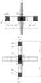
- fig. 6 shows the A-A section through the axis of the first stand
- Fig. 7 shows the B-B section through the axis of the second stand
- Fig. 8 shows the C-C section through the axis of the third stand
- Fig. 9 shows the D-D section through the axis of the fourth stand
- Fig. 10 shows the E-E section through the rolling axis in the skew stand.
- a method of rolling balls, especially from foot sections of scrap railway rails consists in that a blank 17 in the shape of a section of a railway rail head was heated to the temperature appropriate for hot working, which was 1200°C. Then, the heated blank 17 was placed in the grooves 2a and 2b of the feeding rollers 1a and 1b. After that, the feeding rollers 1a and 1b were set to rotate at the same speed n1 of 60 rpm, and the blank 17 was moved towards the front guide 3 at a constant speed V1 of 100 mm/s. Subsequently, the grooved rolls of the first stand 5a and 5b were set to rotate at a constant speed n2 of 12 rpm in opposite directions.
- the grooved rolls of the second stand 11a and 11b were set to rotate at a constant speed n3 of 15 rpm in opposite directions
- the grooved rolls of the third stand 17a and 17b were set to rotate at a constant speed n4 of 16 rpm in opposite directions
- the grooved rolls of the fourth stand 13a and 13b were set to rotate at a constant speed n5 of 20 rpm in opposite directions.
- the guide rollers 15a and 15b were set to rotate at a constant speed n6 of 35 rpm in the same direction and at the same time the helical rollers 31a and 31b were set to rotate at the same speeds n7 of 45 rpm in the same direction.
- the blank 30 was guided into a guide hole 4 of the front guide of the first stand 3, and the blank 17 was moved towards the grooved rolls of the first stand 5a and 5b, and the blank 30 was guided into the trapezoid-shaped grooves 6a and 6b located on the surface of the grooved rolls of the first stand 5a and 5b.
- the grooves 6a and 6b of the grooved rolls of the first stand 5a and 5b had a depth h1 of 50 mm, which was less than half the height of the blank 30, and a width b1 of 42 mm which was greater than the thickness of the blank 30, and the angle of inclination ⁇ 1 of the side walls of grooves 6a and 6b of grooved rolls of the first stand 5a and 5b equal to 32°, which was greater than the angle of inclination of the blank 30 walls.
- the diameter D1 of both grooved rolls of the first stand 5a and 5b was the same and was 500 mm.
- the axes of both grooved rolls of the first stand 5a and 5b were located in a horizontal plane, and the distance between axes of both grooved rolls of the first stand 5a and 5b was equal to the diameter D1 of 500 mm of the grooved rolls of the first stand 5a and 5b.
- the blank 30 was gripped with the groove surfaces 6a and 6b of the grooved rolls of the first stand 5a and 5b and the blank 30 in the shape of a railway rail foot was flow formed into a rhombus-shaped blank 30b, the height of the cut formed by the trapezoidal grooves 6a and 6b of the grooved rolls of the first stand 5a and 5b had a depth h1 equal to 50 mm, which was greater than the width b1 equal to 42 mm of the cut formed by the trapezoidal grooves 6a and 6b of the grooved rolls of the first stand 5a and 5b.
- the rhombus-shaped blank 30b was held in the rolling axis behind the rolling gap of the grooved rolls of the first stand 5a and 5b in the rhombus-shaped hole 8 of the rear guide of the first stand 7. Then the blank 30b was moved towards the second rolling stand, which consisted of two identical grooved rolls of the second stand 11a and 11b, which had the same diameter D2 of 500 mm, and surfaces with trapezoidal grooves 12a and 12b with a depth h2 of 32 mm which was less than the depth h1 of the trapezoidal grooves 6a and 6b of the grooved rolls of the first stand 5a and 5b, and a width b2 of 52 mm of the trapezoidal grooves 12a and 12b of the grooved rolls of the second stand 11a and 11b which was greater than the width b1 of the trapezoidal grooves 6a and 6b of the grooved rolls of the first stand 5a and 5b.
- the axes of the grooved rolls of the second stand 11a and 11b were located horizontally and spaced apart by the diameter D2 of the grooved rolls of the second stand 11a and 11b, equal to 500 mm. Thereafter, the end of the blank 30b was guided into a hole 10 of the entry guide 9 of the second rolling stand, where its position was maintained.
- the end of the blank 30b was guided into the trapezoid-shaped grooves 12a and 12b, which were located on the cylindrical surfaces of the grooved rolls of the second stand 11a and 11b, and the blank 30b with a rhombus-shaped cross-section was flow formed into a blank 30c with nearly rhombic cross-section, wherein the height 2h2 of 64 mm of the cross-section of the blank 30c was less than the height 2h1 of 100 mm of the cross-section of the blank 30b after rolling in the trapezoidal grooves 6a and 6b of the grooved rolls of the first stand 5a and 5b.
- the rolled blank 30c was guided in a rhombus-shaped hole 14 of the rear guide 13 of the second rolling stand, then the blank 30c was guided into a guide hole 16 of the front guide of the third stand 15 and the blank 30c was moved towards the grooved rolls of the third stand 17a and 17b. After that, the blank 30c was guided into the oval-shaped grooves 18a and 18b, located on the surface of the grooved rolls of the third stand 17a and 17b, which had a depth h3 equal to 16 mm, which was less than the half the height of the blank 30c, and a width b3 equal to 74 mm, which was greater than the thickness of the blank 30c.
- the diameter D3 of 500 mm of both grooved rolls of the third stand 17a and 17b was the same.
- the axes of both grooved rolls of the third stand 17a and 17b were located in a vertical plane, and the distance between axes of both grooved rolls of the third stand 17a and 17b was equal to the diameter D3 of the grooved rolls of the third stand 17a and 17b and was 500 mm.
- the blank 30c was gripped with the groove surfaces 18a and 18b of the grooved rolls of the third stand 17a and 17b and the rhombus-shaped blank 30c was flow formed into an oval-shaped blank 30d, wherein the vertical axis of the oval cut formed by the grooves 18a and 18b of the grooved rolls of the third stand 17a and 17b had a length b3 equal to 68 mm, which was greater than the height 2h2, equal to 70 mm, of the rhombic cross-section of the blank 30c rolled in the trapezoidal grooves of the second stand 12a and 12b.
- the oval-shaped blank 30d was held in the rolling axis behind the rolling gap of the grooved rolls of the third stand 17a and 17b in an oval-shaped hole 20 of the rear guide of the third stand 19. After that, the blank 30d was moved towards the fourth rolling stand, which consisted of two identical grooved rolls of the fourth stand 23a and 23b, which had the same diameter D4, equal to 500 mm, and the surfaces of which had concave grooves 24a and 24b with a radius R4 of 21.5 mm, equal to half the diameter dk of the rolled ball 36.
- the axes of the grooved rolls of the fourth stand 23a and 23b were located horizontally and spaced apart by a diameter D4 of the grooved rolls of the fourth stand 23a and 23b, equal to 500 mm.
- the end of the blank 30d was guided into a hole 22 of the entry guide 21 of the fourth rolling stand. Then, the end of the blank 30d was guided into the circular-shaped grooves 24a and 24b, which were located on the cylindrical surfaces of the grooved rolls of the fourth stand 23a and 23b, and the blank 30d with an oval-shaped cross-section was flow formed into a bar 30e with nearly circular cross-section, wherein the diameter dp of the bar 30e was 43.5 mm and was greater than the diameter dk of the rolled ball 36 equal to 42 mm.
- the rolled bar 30e was moved in the grooves 28a and 28b of the guide rollers 27a and 27b towards the skew rolls 31a and 31b, and the bar 30e was guided into a hole of the feeding sleeve 29, in which the correct position of the bar 30e was maintained. Then, using the guide rollers 27a and 27b, the bar 30e was guided into the workspace of the skew rolling mill, consisting of two helical rolls 31a and 31b and two guides 35a and 35b. Both helical rolls 31a and 31b had the same working diameter D of 340 mm, and their axes were twisted in opposite directions relative to the rolling axis by the same twist angle of the rolls ⁇ , which was 3.5°.
- the guides 35a and 35b were parallel to the rolling axis, and the distance between the working surfaces of the guides 35a and 35b was greater than the diameter dp of the rolled bar 30e, and during the rolling was equal to 45 mm. Then, the end of the bar 30e was gripped with conical surfaces 32a and 32b located in the entry zone of two helical cylinders 31a and 31b, which rotated at the same speeds n7 in the same direction, and the bar 30e was set to rotate at a constant speed n8 of 180 rpm in the direction opposite to the direction of rotation of the helical rolls 31a and 31b, and the bar 30e was moved at a speed V2 of 50 mm/s, and using the conical surfaces 32a and 32b the cross-section of the bar 30e was flow formed, by shaping a transitional conical surface with an opening angle ⁇ of 4°, and then the cross-section of the bar 30e was calibrated using two cylindrical surfaces 33a and 33b located behind the conical surfaces of the helical
- helical protrusions located on the surfaces of the helical rolls 31a and 31b were sunk into the cylindrical surface of the earlier calibrated bar 30e.
- the concave side surfaces 34a and 34b of the helical protrusions of the helical rolls 31a and 31b had concave side surfaces 34a and 34b, the radius Rk of which was 21 mm and was equal to half the diameter dk of the rolled ball 36.
- annular grooves with spherical side surfaces were gradually formed on the blank 30e.
- the blank was held in the workspace by two guides 35a and 35b, located opposite each other, between the helical rolls 31a and 31b.
Landscapes
- Engineering & Computer Science (AREA)
- Mechanical Engineering (AREA)
- Metal Rolling (AREA)
- Forging (AREA)
Applications Claiming Priority (1)
| Application Number | Priority Date | Filing Date | Title |
|---|---|---|---|
| PL442342A PL246043B1 (pl) | 2022-09-21 | 2022-09-21 | Sposób walcowania kul |
Publications (1)
| Publication Number | Publication Date |
|---|---|
| EP4342599A1 true EP4342599A1 (fr) | 2024-03-27 |
Family
ID=88017844
Family Applications (1)
| Application Number | Title | Priority Date | Filing Date |
|---|---|---|---|
| EP23193049.6A Pending EP4342599A1 (fr) | 2022-09-21 | 2023-08-23 | Procédé de laminage de billes |
Country Status (2)
| Country | Link |
|---|---|
| EP (1) | EP4342599A1 (fr) |
| PL (1) | PL246043B1 (fr) |
Citations (6)
| Publication number | Priority date | Publication date | Assignee | Title |
|---|---|---|---|---|
| US1910271A (en) * | 1931-12-16 | 1933-05-23 | Sheffield Steel Corp | Process and apparatus for rerolling railroad rails |
| PL225772A1 (fr) | 1979-07-20 | 1981-04-10 | Fortschritt Veb K | |
| PL219678B1 (pl) * | 2011-05-11 | 2015-06-30 | Lubelska Polt | Narzędzie do walcowania skośnego wyrobów typu kule |
| PL423386A1 (pl) | 2017-11-08 | 2019-05-20 | Lubelska Polt | Sposób walcowania prętów ze środników złomowanych szyn kolejowych |
| PL239815B1 (pl) * | 2020-02-21 | 2022-01-10 | Lubelska Polt | Sposób walcowania prętów stalowych |
| PL241107B1 (pl) * | 2017-12-14 | 2022-08-01 | Lubelska Polt | Sposób walcowania skośnego odkuwek kul |
Family Cites Families (4)
| Publication number | Priority date | Publication date | Assignee | Title |
|---|---|---|---|---|
| WO2016047076A1 (fr) * | 2014-09-22 | 2016-03-31 | Jfeスチール株式会社 | Procédé de fabrication de rail et appareil de fabrication de rail |
| CN107520249B (zh) * | 2017-07-28 | 2020-02-07 | 包头钢铁(集团)有限责任公司 | 一种全万能四辊成品孔型轧制钢轨的方法 |
| CN109759452B (zh) * | 2019-03-28 | 2020-06-09 | 攀钢集团攀枝花钢钒有限公司 | 构建钢轨规格调整量模型的方法 |
| CN111282993A (zh) * | 2020-03-13 | 2020-06-16 | 中冶赛迪上海工程技术有限公司 | 近终型轨形坯短流程连铸连轧生产方法及系统 |
-
2022
- 2022-09-21 PL PL442342A patent/PL246043B1/pl unknown
-
2023
- 2023-08-23 EP EP23193049.6A patent/EP4342599A1/fr active Pending
Patent Citations (6)
| Publication number | Priority date | Publication date | Assignee | Title |
|---|---|---|---|---|
| US1910271A (en) * | 1931-12-16 | 1933-05-23 | Sheffield Steel Corp | Process and apparatus for rerolling railroad rails |
| PL225772A1 (fr) | 1979-07-20 | 1981-04-10 | Fortschritt Veb K | |
| PL219678B1 (pl) * | 2011-05-11 | 2015-06-30 | Lubelska Polt | Narzędzie do walcowania skośnego wyrobów typu kule |
| PL423386A1 (pl) | 2017-11-08 | 2019-05-20 | Lubelska Polt | Sposób walcowania prętów ze środników złomowanych szyn kolejowych |
| PL241107B1 (pl) * | 2017-12-14 | 2022-08-01 | Lubelska Polt | Sposób walcowania skośnego odkuwek kul |
| PL239815B1 (pl) * | 2020-02-21 | 2022-01-10 | Lubelska Polt | Sposób walcowania prętów stalowych |
Non-Patent Citations (1)
| Title |
|---|
| Z. PATERJ. TOMCZAK: "Helical rolling of balls for ball mills", 2012, WYDAWNICTWO POLITECHNIKI LUBELSKIEJ, article "Walcowanie srubowe kul do mlynow kulowych" |
Also Published As
| Publication number | Publication date |
|---|---|
| PL246043B1 (pl) | 2024-11-25 |
| PL442342A1 (pl) | 2024-03-25 |
Similar Documents
| Publication | Publication Date | Title |
|---|---|---|
| RU2735435C1 (ru) | Способ винтовой прокатки прутков | |
| JPWO2006025369A1 (ja) | ダイス、段付き金属管の製造方法及び段付き金属管 | |
| EP4342599A1 (fr) | Procédé de laminage de billes | |
| RU2461436C1 (ru) | Способ изготовления тонкостенных корпусов переменного сечения | |
| EP4342598A1 (fr) | Procédé de laminage de billes | |
| JP5615938B2 (ja) | 管圧延プラント | |
| RU2405646C1 (ru) | Способ ротационной вытяжки оболочек из трубных заготовок и трубная заготовка для изготовления оболочек ротационной вытяжкой | |
| JP4569317B2 (ja) | 超薄肉継目無金属管の製造方法 | |
| JP7549212B2 (ja) | 継目無金属管の製造方法 | |
| RU2635685C1 (ru) | Способ прошивки в стане винтовой прокатки | |
| PL246042B1 (pl) | Sposób walcowania kul | |
| RU2037348C1 (ru) | Способ прошивки заготовок и получения труб в стане продольной прокатки | |
| RU2361689C1 (ru) | Способ получения гильз | |
| PL241107B1 (pl) | Sposób walcowania skośnego odkuwek kul | |
| RU2207200C2 (ru) | Способ производства бесшовных горячекатаных труб большого диаметра повышенной точности по стенке на трубопрокатных установках с пилигримовыми станами | |
| JP4314972B2 (ja) | 金属管の定径圧延方法 | |
| SU1135518A1 (ru) | Способ изготовлени гнутых профилей и устройство дл изготовлени гнутых профилей | |
| RU2329884C1 (ru) | Способ волочения проволоки в роликовых волоках | |
| RU2542135C2 (ru) | Способ производства конусных длинномерных полых металлических изделий горячей прокаткой | |
| RU2773967C1 (ru) | Способ винтовой прошивки | |
| RU2315671C1 (ru) | Способ винтовой прокатки труб | |
| US2050236A (en) | Apparatus for forming tubular blanks | |
| RU2368439C1 (ru) | Способ изготовления контурного опалубочного профиля | |
| RU2401170C1 (ru) | Способ асимметричной холодной прокатки труб | |
| RU2630158C1 (ru) | Способ подготовки заготовки к винтовой прокатке |
Legal Events
| Date | Code | Title | Description |
|---|---|---|---|
| PUAI | Public reference made under article 153(3) epc to a published international application that has entered the european phase |
Free format text: ORIGINAL CODE: 0009012 |
|
| STAA | Information on the status of an ep patent application or granted ep patent |
Free format text: STATUS: THE APPLICATION HAS BEEN PUBLISHED |
|
| AK | Designated contracting states |
Kind code of ref document: A1 Designated state(s): AL AT BE BG CH CY CZ DE DK EE ES FI FR GB GR HR HU IE IS IT LI LT LU LV MC ME MK MT NL NO PL PT RO RS SE SI SK SM TR |
|
| STAA | Information on the status of an ep patent application or granted ep patent |
Free format text: STATUS: REQUEST FOR EXAMINATION WAS MADE |
|
| 17P | Request for examination filed |
Effective date: 20240708 |
|
| RBV | Designated contracting states (corrected) |
Designated state(s): AL AT BE BG CH CY CZ DE DK EE ES FI FR GB GR HR HU IE IS IT LI LT LU LV MC ME MK MT NL NO PL PT RO RS SE SI SK SM TR |