EP4345241A1 - Système de contre-enveloppe et dispositif de fermeture d'une ouverture murale d'un bâtiment doté d'un tel système de contre-enveloppe - Google Patents
Système de contre-enveloppe et dispositif de fermeture d'une ouverture murale d'un bâtiment doté d'un tel système de contre-enveloppe Download PDFInfo
- Publication number
- EP4345241A1 EP4345241A1 EP23200486.1A EP23200486A EP4345241A1 EP 4345241 A1 EP4345241 A1 EP 4345241A1 EP 23200486 A EP23200486 A EP 23200486A EP 4345241 A1 EP4345241 A1 EP 4345241A1
- Authority
- EP
- European Patent Office
- Prior art keywords
- cladding
- profile
- shell system
- cladding profile
- facing
- Prior art date
- Legal status (The legal status is an assumption and is not a legal conclusion. Google has not performed a legal analysis and makes no representation as to the accuracy of the status listed.)
- Withdrawn
Links
Images




Classifications
-
- E—FIXED CONSTRUCTIONS
- E06—DOORS, WINDOWS, SHUTTERS, OR ROLLER BLINDS IN GENERAL; LADDERS
- E06B—FIXED OR MOVABLE CLOSURES FOR OPENINGS IN BUILDINGS, VEHICLES, FENCES OR LIKE ENCLOSURES IN GENERAL, e.g. DOORS, WINDOWS, BLINDS, GATES
- E06B3/00—Window sashes, door leaves, or like elements for closing wall or like openings; Layout of fixed or moving closures, e.g. windows in wall or like openings; Features of rigidly-mounted outer frames relating to the mounting of wing frames
- E06B3/30—Coverings, e.g. protecting against weather, for decorative purposes
- E06B3/301—Coverings, e.g. protecting against weather, for decorative purposes consisting of prefabricated profiled members or glass
- E06B3/305—Covering metal frames with plastic or metal profiled members
-
- E—FIXED CONSTRUCTIONS
- E06—DOORS, WINDOWS, SHUTTERS, OR ROLLER BLINDS IN GENERAL; LADDERS
- E06B—FIXED OR MOVABLE CLOSURES FOR OPENINGS IN BUILDINGS, VEHICLES, FENCES OR LIKE ENCLOSURES IN GENERAL, e.g. DOORS, WINDOWS, BLINDS, GATES
- E06B1/00—Border constructions of openings in walls, floors, or ceilings; Frames to be rigidly mounted in such openings
- E06B1/006—Border constructions of openings in walls, floors, or ceilings; Frames to be rigidly mounted in such openings of curvilinear outline
-
- E—FIXED CONSTRUCTIONS
- E06—DOORS, WINDOWS, SHUTTERS, OR ROLLER BLINDS IN GENERAL; LADDERS
- E06B—FIXED OR MOVABLE CLOSURES FOR OPENINGS IN BUILDINGS, VEHICLES, FENCES OR LIKE ENCLOSURES IN GENERAL, e.g. DOORS, WINDOWS, BLINDS, GATES
- E06B3/00—Window sashes, door leaves, or like elements for closing wall or like openings; Layout of fixed or moving closures, e.g. windows in wall or like openings; Features of rigidly-mounted outer frames relating to the mounting of wing frames
- E06B3/30—Coverings, e.g. protecting against weather, for decorative purposes
- E06B3/301—Coverings, e.g. protecting against weather, for decorative purposes consisting of prefabricated profiled members or glass
- E06B3/306—Covering plastic frames with metal or plastic profiled members
-
- E—FIXED CONSTRUCTIONS
- E06—DOORS, WINDOWS, SHUTTERS, OR ROLLER BLINDS IN GENERAL; LADDERS
- E06B—FIXED OR MOVABLE CLOSURES FOR OPENINGS IN BUILDINGS, VEHICLES, FENCES OR LIKE ENCLOSURES IN GENERAL, e.g. DOORS, WINDOWS, BLINDS, GATES
- E06B3/00—Window sashes, door leaves, or like elements for closing wall or like openings; Layout of fixed or moving closures, e.g. windows in wall or like openings; Features of rigidly-mounted outer frames relating to the mounting of wing frames
- E06B3/04—Wing frames not characterised by the manner of movement
- E06B3/06—Single frames
- E06B3/08—Constructions depending on the use of specified materials
- E06B3/20—Constructions depending on the use of specified materials of plastics
- E06B3/22—Hollow frames
- E06B3/221—Hollow frames with the frame member having local reinforcements in some parts of its cross-section or with a filled cavity
- E06B3/222—Hollow frames with the frame member having local reinforcements in some parts of its cross-section or with a filled cavity with internal prefabricated reinforcing section members inserted after manufacturing of the hollow frame
-
- E—FIXED CONSTRUCTIONS
- E06—DOORS, WINDOWS, SHUTTERS, OR ROLLER BLINDS IN GENERAL; LADDERS
- E06B—FIXED OR MOVABLE CLOSURES FOR OPENINGS IN BUILDINGS, VEHICLES, FENCES OR LIKE ENCLOSURES IN GENERAL, e.g. DOORS, WINDOWS, BLINDS, GATES
- E06B3/00—Window sashes, door leaves, or like elements for closing wall or like openings; Layout of fixed or moving closures, e.g. windows in wall or like openings; Features of rigidly-mounted outer frames relating to the mounting of wing frames
- E06B3/30—Coverings, e.g. protecting against weather, for decorative purposes
- E06B3/301—Coverings, e.g. protecting against weather, for decorative purposes consisting of prefabricated profiled members or glass
- E06B3/302—Covering wooden frames with metal or plastic profiled members
-
- E—FIXED CONSTRUCTIONS
- E06—DOORS, WINDOWS, SHUTTERS, OR ROLLER BLINDS IN GENERAL; LADDERS
- E06B—FIXED OR MOVABLE CLOSURES FOR OPENINGS IN BUILDINGS, VEHICLES, FENCES OR LIKE ENCLOSURES IN GENERAL, e.g. DOORS, WINDOWS, BLINDS, GATES
- E06B3/00—Window sashes, door leaves, or like elements for closing wall or like openings; Layout of fixed or moving closures, e.g. windows in wall or like openings; Features of rigidly-mounted outer frames relating to the mounting of wing frames
- E06B3/54—Fixing of glass panes or like plates
- E06B3/58—Fixing of glass panes or like plates by means of borders, cleats, or the like
- E06B3/5807—Fixing of glass panes or like plates by means of borders, cleats, or the like not adjustable
- E06B3/5821—Fixing of glass panes or like plates by means of borders, cleats, or the like not adjustable hooked on or in the frame member, fixed by clips or otherwise elastically fixed
Definitions
- the present invention relates to an attachment shell system for a device for closing a wall opening of a building, in particular for an openable or non-openable window or for a door with at least one first, in particular at least partially curved along a longitudinal direction or extending at an angle, in particular at right angles or at an acute angle first cladding profile, which is designed and set up alone or together with further cladding profiles for cladding at least one frame section of a frame of the device, the first cladding profile having an inside facing the frame section in the intended installed state and an outside facing away from the frame section in the intended installed state.
- the invention relates to a device for closing a wall opening in a building with such an attachment shell system.
- composite windows and doors are now very often used in which the sash frame is made of a different material than the facing shell for it.
- This type of construction has proven successful, among other things, because the area of the composite window or door that is exposed to the weather can be covered with a material that is less susceptible to the weather and is therefore durable. In contrast, a cheaper material can be chosen for the interior, which also has advantages in terms of appearance and feel. Furthermore, this enables an optimized thermal separation between the inside and outside.
- Typical material pairings for such composite windows and doors are wood-aluminium, plastic-aluminium or similar. In the context of the present For the sake of ease of reading, only the term composite windows is used in the application, although this also expressly includes composite doors, as far as transferable.
- Aluminum facings for composite windows are usually made from extruded or continuous cast profiles. These are mass-produced pieces that are straight along their longitudinal direction, i.e. along the extrusion direction, and are cut to size for the individual window. For right-angled corners, this is done at an angle of 45° to the longitudinal direction of the extruded or continuous cast profile in order to define the miter between two adjacent profiles. To produce a visually appealing facing and to prevent moisture from penetrating the space between the sash frame and the facing, the profiles that meet are welded in the miter area and then ground.
- the method described above can in principle also be used if the angle between two meeting profiles is acute or obtuse.
- the angle at which the profile is shortened must be adjusted accordingly.
- the challenge when installing the facing shell is that the miter is lengthened, which also increases the length of the line weld.
- this is more demanding for the installer, but on the other hand, the increased temperature input due to the longer weld seam promotes the build-up of internal stresses in the miter area and thus the risk of material distortion.
- Bending causes material compression on the side of the profile facing the bending radius center and material stretching on the side of the profile facing away from the bending radius center. Compression on the inside can lead to distortions, which require increased sanding effort. Even if this sanding is carried out to a high quality, there is a risk that a subsequent surface coating, for example a powder coating, the application of a wood decor or an anodized coating, will not produce a homogeneous appearance, as the density and thickness of the material in this area is not homogeneous. Stretching on the outside, in turn, can lead to a weakening of the material and even the formation of (micro) cracks, which have a detrimental effect on both the appearance and the longevity of the facing shell. In practice, the above means that when bending extruded and/or continuous cast profiles, minimum bending radii must be observed, which arise individually from the width and design, in particular the cross-sectional design of the profile.
- a double disadvantage arises from bending extruded or continuously cast profiles for geometry, for example with regard to the dimensional accuracy of the profile. Bending reduces the actual width of the profile by up to a few percent of the original width. This visual impairment is particularly significant when a curved profile directly adjoins a non-curved profile and two profiles of different widths are revealed to the viewer.
- the second disadvantage concerns the attachment of the facing shell to the sash frame. On the side of the attachment shell facing the sash, recesses are often provided either in sections or through them, in which, among other things, fastening devices for fastening to the sash are arranged. Such fastening devices are usually clip devices or rotary holders.
- the width of these recesses is defined by the manufacturers of the extruded or continuously cast profiles according to the standardized width of the fastening devices and in the unbent state of the profiles.
- the recesses due to the narrowing of the profile described above, the recesses also become narrower and proper attachment of the profile to the sash frame is not possible or only possible additional manual effort can be guaranteed.
- automatic setting of the clip devices and/or rotary holders is no longer possible due to the geometry changes in conventional round arches. These have to be set manually with great effort.
- the bending process requires a lot of manpower and represents a significant risk from the point of view of occupational safety.
- the extruded or continuous cast profile to be bent is usually heated by an experienced specialist with or over an open flame, thereby giving it the formability required for bending. This requires a great deal of sensitivity to achieve exactly the temperature window required for bending. If the profile is heated too much, there is a risk of undesirable weakening or damage to the material. For example, if an aluminum alloy or a plastic used for this purpose is heated above a certain temperature, an irreversible change in shape and/or structure can occur. The component heated accordingly is therefore scrap.
- the desired bending radius on the finished component can only be achieved through a large number of iterative bending processes, each of which requires the bending machine to be preset accordingly. This is very complex. For more complicated geometries, e.g. with several different bending radii or If the bending radii vary on the same profile, this cost increases accordingly. In order to achieve different bending radii on one and the same profile, in addition to the complex adjustment work mentioned above, it may also be necessary to have a number of bending machines, bending molds and/or roller sets available, depending on the size of the bending radii to be produced. This means a considerable amount of space and investment.
- the invention is therefore based on the object of specifying a facing shell system that overcomes the disadvantages of the prior art, e.g. the stretched or compressed material, the resulting problems with the visible surfaces, the limited radii that can be achieved and the labor-intensive and personnel-dependent process. Furthermore, a facing shell system is to be specified that can be produced with greater reproducibility and greater process reliability, particularly with regard to dimensional accuracy. Furthermore, the object of the invention is to specify a facing shell system that can be provided within shorter delivery times.
- An attachment shell system for a device for closing a wall opening of a building, in particular for an openable or non-openable window or for a door, has at least a first, in particular along a longitudinal direction L at least in sections curved or angular, in particular right-angled or acute-angled, first cladding profile, which is designed and set up alone or together with further cladding profiles for cladding at least one frame section of a frame of the device, the first cladding profile having an inside facing the frame section in the intended installed state and has an outside facing away from the frame section when installed as intended.
- the facing shell system is further developed in such a way that the first cladding profile is produced by an additive manufacturing process or at least all non-flat boundary surfaces of the inside are produced using a machining manufacturing process, in particular by milling, from a blank, in particular a plate- or cuboid-shaped semi-finished blank .
- the post-processing effort is reduced enormously. Warping, especially on the inside of the curved profile, no longer occurs and therefore does not need to be sanded down. Thanks to the homogeneous, stress-free material structure, an attractive appearance can be created with manageable effort during the subsequent powder coating of the surface. Furthermore, it should be emphasized that the material weakening that occurs due to the bending of the profile, which can be observed in particular on the radial outside of the curved profile, is not present in an facing shell system according to the present invention, which is why the resulting disadvantages with regard to the appearance and longevity of the cladding profile does not matter.
- Another advantage of the facing shell system according to the invention is that by using machining or additively manufactured cladding profiles, components of the same dimensions can be installed to a large extent. Even experienced production personnel are not able to bend identical curved profiles with tight tolerances, especially with larger profile elements, because despite the same conditions they are always hand-made individual pieces. This deficit can be overcome through the possibility of fully automating the molding process.
- the manufacturer of the facing shell system according to the invention has the opportunity to offer its customers a wider range of possible design variants. Since minimum bending radii no longer have to be taken into account, even narrow curves can be easily achieved. Even more complicated profiles, such as those with a series of different radii, do not pose a challenge during production, as they can be reliably produced with consistent precision and dimensional accuracy.
- the facing shell system according to the invention is suitable not only for the use of cladding profiles that are curved at least in sections along a longitudinal direction, but also for cladding profiles that run at an angle, in particular at right angles or at an acute angle.
- cladding profiles which were produced using a metal-cutting manufacturing process or an additive manufacturing process, mitres in the facing shell system can be completely avoided. Instead, it is possible to make all transition areas between two adjacent cladding profiles blunt. In the case of a weld seam to connect the two cladding profiles, their length can be minimized, which reduces the manual effort on the one hand and the possible temperature input on the other.
- At least one non-planar boundary surface of the outside is/are produced by a machining manufacturing process, in particular by milling, or by laser cutting or by water jet cutting or by a combination of these manufacturing processes.
- At least one flat boundary surface of the outside is an unprocessed outer surface of the blank, with the flat boundary surface of the outside being in particular a primary visible surface.
- a reduction in the number of surfaces to be processed can be achieved if, for example, at least one flat boundary surface of the outside is formed on the outside by an unprocessed outer surface of the blank.
- an unprocessed outer surface can, for example, be a primary visible surface, which is permanently visible, for example, when the facing shell system is installed as intended.
- an unprocessed outer surface can also be a secondary visible surface, which is at least temporarily covered when the facing shell system is installed as intended or may have a subordinate visibility for other reasons.
- the first cladding profile has at least one fastening device, in particular a clip device or a rotary holder for fastening the first cladding profile to the device.
- a fastening device in particular a clip device or a rotary holder
- the fastening device can be standardized elements that are designed for the connection of facing shell systems or cladding profiles to the sash frame or to the stick frame.
- Mechanical connectors represent an alternative to the weld seam. If the transition area between two adjacent cladding profiles is made blunt, as described above, the effort involved in installing the facing shell system can be reduced by using mechanical connectors.
- the invention also makes it possible for the first time to use sensitive surface coatings, such as the anodizing process, without visually affecting the coated surface.
- sensitive surface coatings such as the anodizing process
- the anodizing process cannot be used with satisfactory optical results due to the required heating/heating of the profile.
- the cladding profile of the facing shell system has a groove-like recess at least in sections along its longitudinal extension direction, which serves in particular to accommodate one or more fastening devices, mechanical connectors or sealing profiles.
- the depth added by the cladding profile can be reduced and the entire device thus giving it a slimmer appearance.
- the at least one fastening device and/or the at least one mechanical connector are arranged in the at least one recess.
- the fastening of the at least one fastening device and/or the at least one mechanical connector can be carried out either by means of a detachable joining method, such as screws or clamps, or by means of a non-detachable joining method, such as gluing or welding. In any case, this ensures that there is a secure connection or connection of the first cladding profile to the device or an adjacent cladding profile.
- the manufacturing method of the first cladding profile also enables the integral formation of these components with the first cladding profile.
- the prerequisite for this is that the corresponding requirements in terms of stability and flexibility can be achieved with the material used.
- Both the CNC milling machine and the 3D printer are capable of producing components with the necessary precision.
- adjacent cladding profiles are connected to one another, as already indicated above. This can be done either by means of mechanical connectors, which are particularly useful when there is a blunt transition area, or by a thermal joining process, in particular by welding, which has advantages in transition areas with a miter. Basically, the connection of adjacent cladding profiles serves to create an attractive appearance and to seal against the penetration of moisture, for example, into the space between the facing shell system and the sash frame.
- At least one cladding profile of the facing shell system according to the invention is made from a metal, for example aluminum or an aluminum alloy, or from plastic, for example a polyamide or from a surface-coated material.
- a metal for example aluminum or an aluminum alloy
- plastic for example a polyamide or from a surface-coated material.
- the first cladding profile is a partial cross-sectional profile of a complex cladding profile.
- the latter is thus composed of the first cladding profile and at least one further partial cross-sectional profile, wherein the connection between the first cladding profile and the at least one further partial cross-sectional profile can be made by gluing, welding, screwing, clamping or another joining method.
- the further partial cross-sectional profile can, according to an advantageous embodiment, be made of a different material than the first partial cross-sectional profile. This is particularly useful if the further partial cross-sectional profile is an extruded profile or a continuously cast profile, which runs in a straight line along its longitudinal direction. Such profiles made by the meter are cheaper to manufacture or purchase and thus enable economically advantageous production of the facing shell system.
- the production of the first cladding profile using a machining process or an additive manufacturing process allows a free design of the outer contour, since this no longer depends on the bending contour, as is the case with the bending of extruded or continuous cast profiles.
- the facing shell system consists of a one-piece frame, which is formed only from a first cladding profile and accordingly consists entirely of a cladding profile milled from a blank or a one-piece additively manufactured cladding profile.
- the facing shell system consists of a multi-part frame, which consists exclusively of first cladding profiles. The facing shell system therefore does not include any extruded or continuously cast profiles, but only cladding profiles that are machined or additively manufactured.
- the facing shell system comprises a cladding profile which is curved along its longitudinal direction and which has a sectionally constant radius of curvature RK1 or several identical and/or different and/or continuously merging radii of curvature RK1, RK2.
- the various curved sections can follow one another directly along the longitudinal direction of the cladding profile or be spaced apart from one another. This opens up a wide range of design options, and manufacturers of facing shell systems or composite windows and doors can offer their customers a wide range of possible window and door shapes.
- the first cladding profile is a rung.
- a device according to the invention for closing a wall opening in a building is characterized in that it is one of those described above Includes facing shell systems.
- this is an openable or non-openable window or door. Due to the diverse design options, especially with regard to the visual appearance, such devices are not only suitable for external doors and windows, but also for connecting and separating different interior spaces.
- At least one frame consists of wood, plastic, for example polyamide, metal, for example aluminum or a composite material.
- at least one frame can also consist of a combination of the aforementioned materials.
- Manufacturers of composite windows and doors can offer their customers a wide range of material combinations, which they can choose depending on their individual preferences.
- An attachment shell system 10 is used, for example, to cover the frame or frame sections 20 of a window 14 or a door.
- Fig. 1 shows such an attachment shell system 10 according to the prior art schematically in a perspective cross section.
- such a window or such a door is generally referred to as a "device 12 for closing a wall opening of a building".
- the closure can be openable or non-openable.
- An openable closure is achieved, for example, by means of an openable window 14 which has a window sash or an openable door which has a door leaf.
- a non-openable closure of the wall opening is achieved, for example, by a permanently installed window without a movable window sash which can neither be opened nor tilted.
- the facing system 10 comprises at least one first cladding profile 16, but in the vast majority of cases has a plurality of Cladding profiles, for example the first cladding profile 16 and at least one further cladding profile 18.
- the cladding profiles 16, 18 When used on a composite window or when renovating existing windows/existing doors, the cladding profiles 16, 18 are placed, for example, on an outside of the frame sections 20 of a window sash/door sash or a window frame/door frame.
- the cladding profiles 16, 18 form a cladding of the frame section 20 or the entire frame and are clipped onto the outside of the frame section 20, for example using fastening devices, in particular clip devices or rotary holders, or are mechanically fastened there in another suitable manner.
- the cladding profiles 16, 18 are usually designed as extruded aluminum profiles or as continuously cast aluminum profiles.
- the cladding profiles 16, 18 have a straight longitudinal extension direction L as extruded aluminum profiles or continuously cast aluminum profiles and are preferably thin-walled in cross-section with a large number of ribs and/or webs and/or cavities.
- the ribs and/or webs can be designed as an integral clip device or as a rotary holder.
- Fig. 2a schematically shows in cross section another cladding profile 18 according to the prior art, manufactured as an extruded aluminum profile or extruded aluminum profile.
- the first cladding profile 16 has an inner side 10A facing the frame section 20 in the intended installed state and an outer side 10B facing away from the frame section 20 in the intended installed state.
- all invisible surface components that are optically hidden by the frame section 20 are assigned to the inside 10A of the first cladding profile 16.
- the outside 10B for example, is in the intended condition Visible surfaces, for example a primary visible surface 30 and a secondary visible surface 31 assigned.
- the inner side 10A has at least one, in particular several non-planar boundary surfaces 100A, which can run, for example, parallel to the longitudinal direction L.
- Such non-planar boundary surfaces 100A of the inner side 10A of the first cladding profile 16 are produced according to the invention using a machining manufacturing process, in particular by milling from a blank 35.
- the blank 35 is in particular a plate-shaped or cuboid-shaped semi-finished blank.
- the outer side 10B Due to its non-straight course along the longitudinal direction L, the outer side 10B also has at least one, in particular several, non-planar boundary surfaces 100B. These non-planar boundary surfaces 100B of the outer side 10B are also produced using a machining process, for example by milling or by other suitable manufacturing processes, such as water jet cutting or laser cutting.
- the outside 10B also has at least one flat boundary surface 100C.
- Such a flat boundary surface 100C of the outside 10B can optionally be an unprocessed outer surface 35A of the blank 35.
- the first cladding profile 16 can be produced as a 3D printed component using an additive manufacturing process.
- a first cladding profile 16 of an facing shell system 10 shows Fig. 2b in a first embodiment.
- the cross-sectional contour shown is a cross-section perpendicular to the longitudinal direction L of the first cladding profile 16.
- a first main outer side and a second main outer side of the first cladding profile 16 are, for example, a primary visible surface 30 and a secondary visible surface 31, which are visible on a window or a door in the assembled state.
- a first inner side 32 opposite the first main outer side is, in the assembled state, associated with a frame section 20 (not shown in Fig. 2b ).
- two receiving grooves 33 are milled along the longitudinal direction L in the exemplary embodiment.
- the two receiving grooves 33 serve to accommodate fastening devices 24, which can interact with corresponding counter-fastening devices (not shown) arranged on the frame section 20 (not shown).
- a longitudinal extension direction L of the first cladding profile 16 is in the Figs. 2b and 2c shown in point form. This representation means that in the cross-sectional plane (i.e. the drawing plane) the Figures 2b and 2c Through the first cladding profile 16, the longitudinal extension direction L runs perpendicularly out of the plane of the drawing. A curvature of the longitudinal extension direction L runs towards the viewer to the right, so that the boundary surfaces 100A, 100B of the first cladding profile 16 represent curved, ie non-planar, boundary surfaces.
- Boundary surface 100C and parallel surface areas on the inside 10A represent, for example, flat boundary surfaces. This means that these surfaces can lie in one plane. However, boundary edges, ie outer edges of these surfaces, can have a curved course, for example parallel to the longitudinal direction L.
- a cross-sectional contour of the blank 35 (semi-finished blank) is shown in a dashed line 34.
- the cross-sectional contour of the blank 35 is rectangular in the above-mentioned embodiment.
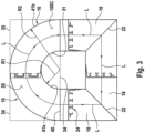
- the first cladding profile 16 according to Fig. 2b is - as in Fig.3 shown - curved in plan view along the longitudinal direction L. In plan view according to Fig.3 This ensures an arched course of the first cladding profile 16. In the plan view according to Fig.3 is by means of the The outline of the blank 35 is shown in plan view by the dashed line 34. According to the invention, a curved inner contour 41a with the radius R1 and a curved outer contour 41b with the radius R2 are formed from the blank 35.
- the facing shell system 10 shown has, in addition to the first cladding profile 16, a total of three further cladding profiles 18, each of which has a rectilinear longitudinal extension direction L. To form right angles, miter cuts are available, which form the miters 22. As shown in the cross-sectional contours of the straight, additional cladding profiles 18, these are designed in the classic manner as extruded profiles or continuously cast profiles. Due to the straight course of the longitudinal direction L, such a configuration is easily possible and can also be carried out cost-effectively.
- the first cladding profile 16, which has a curved course in the longitudinal direction L is, however, designed according to the invention as a machined component made from the blank 35 or as an additively manufactured 3-D printed component.
- Fig.4 an embodiment of the facing shell system 10 according to the invention is shown, which is formed from two first cladding profiles 16, which are designed as components produced by a machining process or as additively manufactured components, i.e. does not contain any cladding profiles 18 in continuous casting or extruded construction.
- the upper cladding profile 16 is as in the embodiment according to Fig.3 in plan view, it is formed in an arc shape along the longitudinal direction L, whereas the lower part is formed as a cladding profile 16 with a U-shaped spatial shape in plan view, wherein the entire U-shaped cladding profile 16 is also formed as a component manufactured by a machining process or as an additively manufactured component (3D printing).
- FIG. 2c A further embodiment of a first cladding profile 16 of an facing shell system 10 according to the invention is shown in Fig. 2c shown in cross section.
- the cladding profile 16 is composed of a first profile section 28A and a second profile section 28B and thus forms a complex cladding profile.
- the profile sections 28A and 28B are each designed as a component, which are manufactured using a machining manufacturing process or using an additive manufacturing process.
- the fastening devices 24 are placed directly on the flat inside 32 of the second profile section 28, for example glued.
- Fig. 5a shows a highly schematic view of an inventive facing shell system 10 for a so-called arched window.
- the vertically upper first cladding profile 16 is provided according to the invention as a machined or additively manufactured component. It is particularly advantageous that such a first cladding profile 16, which according to the invention is not produced as a curved extruded profile, can have a larger radius of curvature RK1, for example, in a central region, whereas a smaller radius of curvature RK2 can be provided in corner regions.
- Lateral or vertically lower additional cladding profiles 18 can be used for a pointed arch window according to Fig. 5a can easily be designed as a conventional extruded profile or continuous cast profile.
- Possible separation points 40 between the first cladding profile 16 and the vertical additional cladding profiles 18 are expediently arranged in areas in which the first cladding profile 16 runs out in a straight line, for example in its end areas. This makes it considerably easier to connect the first cladding profile 16 to the additional cladding profiles 18.
- FIG. 5b A further embodiment of the facing shell system 10 according to the invention is shown in a highly schematic form in an application for a so-called arched basket window.
- the first cladding profile 16 is also arranged vertically at the top and has a straight middle piece and two curved end pieces, which merge into further vertical cladding profiles 18 at the separation points 40.
- a vertically upper straight area between the separation points 40 ' can optionally be designed as a straight further cladding profile 18 in an extruded or continuously cast construction.
- Fig. 5c shows schematically an application of the inventive facing system 10 on a so-called pointed arch window.
- the vertically lower further cladding profile 18 is designed, for example, as an extruded profile or extruded profile with a straight longitudinal direction L.
- Both lateral cladding profiles with arches are designed as first cladding profiles 16, which were manufactured by means of a machining or additive manufacturing process.
- an arched course of the lateral (first) cladding profiles 16 can also be realized in a particularly simple manner, which has, for example, varying radii of curvature along its longitudinal direction L.
- a course with a smaller radius of curvature RK1 can initially be provided, which then transitions into a course with a larger radius of curvature RK2, for example continuously or stepped.
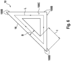
- Fig. 6 shows schematically the advantages of a one-piece facing shell system 10 according to the invention, which only has a single first cladding profile 16 having.
- the schematic application case according to Figure 6 relates, for example, to a triangular window which has acute-angled courses along the longitudinal direction L. With a predetermined width B, depending on the size of the acute angle, a certain length l of a miter cut required in the prior art results. This length l, along which, for example, welding would have to be carried out in the prior art, can be avoided by, for example, a one-piece design of the facing shell system 10 according to the invention from a single first cladding profile 16. Such a one-piece first cladding profile 16 does not cause the need to weld long miters.
- the invention provides a number of advantages.
- the design freedom is high with regard to the sizes of the radii of curvature R1, R2, RK1, RK2 and also the combination of different radii of curvature in one component.
- the procedure disclosed according to the invention makes it possible to produce non-rectilinear cladding profiles 16 with high dimensional accuracy in a process-reliable manner and with a short delivery time.
- a high possible degree of automation allows delivery times to be significantly shortened compared to the state of the art and reduces the need for specialized workers.
Landscapes
- Engineering & Computer Science (AREA)
- Civil Engineering (AREA)
- Structural Engineering (AREA)
- Bending Of Plates, Rods, And Pipes (AREA)
Applications Claiming Priority (1)
| Application Number | Priority Date | Filing Date | Title |
|---|---|---|---|
| DE102022125344.9A DE102022125344A1 (de) | 2022-09-30 | 2022-09-30 | Vorsatzschalensystem sowie Einrichtung zum Verschließen einer Wandöffnung eines Gebäudes mit einem solchen Vorsatzschalensystem |
Publications (1)
| Publication Number | Publication Date |
|---|---|
| EP4345241A1 true EP4345241A1 (fr) | 2024-04-03 |
Family
ID=88236660
Family Applications (1)
| Application Number | Title | Priority Date | Filing Date |
|---|---|---|---|
| EP23200486.1A Withdrawn EP4345241A1 (fr) | 2022-09-30 | 2023-09-28 | Système de contre-enveloppe et dispositif de fermeture d'une ouverture murale d'un bâtiment doté d'un tel système de contre-enveloppe |
Country Status (2)
| Country | Link |
|---|---|
| EP (1) | EP4345241A1 (fr) |
| DE (1) | DE102022125344A1 (fr) |
Citations (3)
| Publication number | Priority date | Publication date | Assignee | Title |
|---|---|---|---|---|
| US5257488A (en) * | 1990-10-01 | 1993-11-02 | Candusso F. Lli S.R.L. Bilicbora | Profile in bendable metal-wood and the products obtained with it |
| DE202019107047U1 (de) * | 2019-12-17 | 2021-03-18 | Rehau Ag + Co | Fenster- oder Türflügel sowie diesen umfassendes Fenster oder diesen umfassende Tür |
| EP3712368B1 (fr) * | 2019-03-18 | 2022-01-12 | Veka AG | Profilé de cadre d'un bâti dormant et/ou de cadre de battant ainsi que son procédé de fabrication |
Family Cites Families (3)
| Publication number | Priority date | Publication date | Assignee | Title |
|---|---|---|---|---|
| DE20003914U1 (de) * | 2000-03-04 | 2000-05-25 | Zeller, Josef, 87769 Oberrieden | Tür mit Lichtausschnitt |
| DE10055780A1 (de) * | 2000-11-10 | 2002-05-29 | Raico Bautechnik Gmbh | Abdeckprofilsystem für Fenster-oder Türprofile |
| DE10129485A1 (de) * | 2001-06-21 | 2003-01-02 | Bernd Schweikart | Verfahren sowie Vorsatzschale für Fenster- und/oder Rahmenprofile |
-
2022
- 2022-09-30 DE DE102022125344.9A patent/DE102022125344A1/de active Pending
-
2023
- 2023-09-28 EP EP23200486.1A patent/EP4345241A1/fr not_active Withdrawn
Patent Citations (3)
| Publication number | Priority date | Publication date | Assignee | Title |
|---|---|---|---|---|
| US5257488A (en) * | 1990-10-01 | 1993-11-02 | Candusso F. Lli S.R.L. Bilicbora | Profile in bendable metal-wood and the products obtained with it |
| EP3712368B1 (fr) * | 2019-03-18 | 2022-01-12 | Veka AG | Profilé de cadre d'un bâti dormant et/ou de cadre de battant ainsi que son procédé de fabrication |
| DE202019107047U1 (de) * | 2019-12-17 | 2021-03-18 | Rehau Ag + Co | Fenster- oder Türflügel sowie diesen umfassendes Fenster oder diesen umfassende Tür |
Also Published As
| Publication number | Publication date |
|---|---|
| DE102022125344A1 (de) | 2024-04-04 |
Similar Documents
| Publication | Publication Date | Title |
|---|---|---|
| DE102016102240A1 (de) | Vorrichtung zum Verbinden von Profilstücken | |
| EP4210932B1 (fr) | Procédé et dispositif destiné au soudage d'au moins deux sections profilées servant aux cadres de fenêtre ou de porte ou aux battants | |
| DE10118791A1 (de) | Verbindungselement | |
| DE19900095C1 (de) | Steckzarge | |
| DE102007043195A1 (de) | Verfahren und Vorrichtung zum Verschweißen von Kunststoffprofilstäben, Anschlag sowie Heizspiegel für eine derartige Vorrichtung | |
| DE3318684A1 (de) | Verfahren zur herstellung von rahmen fuer fenster, tueren aus kunststoffprofilen, insbesondere fluegelrahmen, und damit hergestellter rahmen | |
| DE102013114710A1 (de) | Kunststofffenster- oder türrahmen und Verfahren zur Herstellung eines Kunststofffenster- oder türrahmens | |
| DE3331842A1 (de) | Verfahren zur herstellung einer verbundplatte | |
| EP4345241A1 (fr) | Système de contre-enveloppe et dispositif de fermeture d'une ouverture murale d'un bâtiment doté d'un tel système de contre-enveloppe | |
| EP0792993A2 (fr) | Joint d'angle pour profils | |
| DE102004016832B4 (de) | Vorrichtung zum teilweisen Umspritzen metallischer Einleger mit einem Spritzgießwerkzeug | |
| DE2821133B1 (de) | Verfahren zum Verbinden der Enden von auf Gehrung geschnittenen Hohlprofilen | |
| EP3943703B1 (fr) | Procédé de fixation d'un profilé sur une barre, cadre de fenêtre et dispositif de fabrication d'un cadre de fenêtre ou d'une partie de cadre de fenêtre | |
| DE19533284C1 (de) | Fensterprofil mit verbreiterbarer Beschlags-Aufnahmenut | |
| DE3125883A1 (de) | Gehrungseckverbindung fuer aus profilstaeben zusammengesetzte rahmen, insbes. fenster- und tuerrahmen u. dgl. | |
| EP2418347B1 (fr) | Procédé de fabrication d'une liaison de profil en T | |
| AT512718A1 (de) | Verfahren und Vorrichtung zum Biegen einer Ecke in ein Profil aus thermoplastischem Grundmaterial | |
| EP1096096B1 (fr) | Procédé de montage d'un élément de paroi | |
| DE19739252B4 (de) | Verfahren zum Bearbeiten von zu verschweißenden Hohlkammerprofilen mit Gummidichtung | |
| DD210324A1 (de) | Rahmen aus stabartigen elementarteilen, hauptsaechlich fuer fensterrahmen und fensterfluegel | |
| DE3408373A1 (de) | Verfahren und vorrichtung zur herstellung von eckverbindungen in rahmen aus thermoplastischen, insbesondere hart-pvc-profilen fuer fluegel und rahmen von verglasten tueren und fenstern | |
| DE4041161A1 (de) | Verbindungsvorrichtung fuer eine sprossenkonstruktion und verfahren zur herstellung einer sprossenkonstruktion mit dieser verbindungsvorrichtung | |
| DE10155476B4 (de) | Fenster- oder Türrahmen mit reduzierter Profilbreite und Verfahren zur Herstellung desselben | |
| DE2115794C3 (de) | Eckverbindung für Hohlprofile aus Kunststoff | |
| AT516653A1 (de) | Verfahren zur Ausbildung von Ecken in Profilen |
Legal Events
| Date | Code | Title | Description |
|---|---|---|---|
| PUAI | Public reference made under article 153(3) epc to a published international application that has entered the european phase |
Free format text: ORIGINAL CODE: 0009012 |
|
| STAA | Information on the status of an ep patent application or granted ep patent |
Free format text: STATUS: THE APPLICATION HAS BEEN PUBLISHED |
|
| AK | Designated contracting states |
Kind code of ref document: A1 Designated state(s): AL AT BE BG CH CY CZ DE DK EE ES FI FR GB GR HR HU IE IS IT LI LT LU LV MC ME MK MT NL NO PL PT RO RS SE SI SK SM TR |
|
| STAA | Information on the status of an ep patent application or granted ep patent |
Free format text: STATUS: REQUEST FOR EXAMINATION WAS MADE |
|
| 17P | Request for examination filed |
Effective date: 20241002 |
|
| RBV | Designated contracting states (corrected) |
Designated state(s): AL AT BE BG CH CY CZ DE DK EE ES FI FR GB GR HR HU IE IS IT LI LT LU LV MC ME MK MT NL NO PL PT RO RS SE SI SK SM TR |
|
| STAA | Information on the status of an ep patent application or granted ep patent |
Free format text: STATUS: EXAMINATION IS IN PROGRESS |
|
| 17Q | First examination report despatched |
Effective date: 20250212 |
|
| STAA | Information on the status of an ep patent application or granted ep patent |
Free format text: STATUS: THE APPLICATION IS DEEMED TO BE WITHDRAWN |
|
| 18D | Application deemed to be withdrawn |
Effective date: 20250613 |