EP4345558A1 - Procédé de fonctionnement d'un module de connexion - Google Patents
Procédé de fonctionnement d'un module de connexion Download PDFInfo
- Publication number
- EP4345558A1 EP4345558A1 EP22206798.5A EP22206798A EP4345558A1 EP 4345558 A1 EP4345558 A1 EP 4345558A1 EP 22206798 A EP22206798 A EP 22206798A EP 4345558 A1 EP4345558 A1 EP 4345558A1
- Authority
- EP
- European Patent Office
- Prior art keywords
- installation
- connection
- connection module
- output
- component
- Prior art date
- Legal status (The legal status is an assumption and is not a legal conclusion. Google has not performed a legal analysis and makes no representation as to the accuracy of the status listed.)
- Granted
Links
Images

Classifications
-
- G—PHYSICS
- G05—CONTROLLING; REGULATING
- G05B—CONTROL OR REGULATING SYSTEMS IN GENERAL; FUNCTIONAL ELEMENTS OF SUCH SYSTEMS; MONITORING OR TESTING ARRANGEMENTS FOR SUCH SYSTEMS OR ELEMENTS
- G05B19/00—Program-control systems
- G05B19/02—Program-control systems electric
- G05B19/418—Total factory control, i.e. centrally controlling a plurality of machines, e.g. direct or distributed numerical control [DNC], flexible manufacturing systems [FMS], integrated manufacturing systems [IMS] or computer integrated manufacturing [CIM]
- G05B19/41805—Total factory control, i.e. centrally controlling a plurality of machines, e.g. direct or distributed numerical control [DNC], flexible manufacturing systems [FMS], integrated manufacturing systems [IMS] or computer integrated manufacturing [CIM] characterised by assembly
-
- G—PHYSICS
- G06—COMPUTING OR CALCULATING; COUNTING
- G06F—ELECTRIC DIGITAL DATA PROCESSING
- G06F3/00—Input arrangements for transferring data to be processed into a form capable of being handled by the computer; Output arrangements for transferring data from processing unit to output unit, e.g. interface arrangements
- G06F3/16—Sound input; Sound output
-
- G—PHYSICS
- G05—CONTROLLING; REGULATING
- G05B—CONTROL OR REGULATING SYSTEMS IN GENERAL; FUNCTIONAL ELEMENTS OF SUCH SYSTEMS; MONITORING OR TESTING ARRANGEMENTS FOR SUCH SYSTEMS OR ELEMENTS
- G05B2219/00—Program-control systems
- G05B2219/30—Nc systems
- G05B2219/31—From computer integrated manufacturing till monitoring
- G05B2219/31027—Computer assisted manual assembly CAA, display operation, tool, result
-
- G—PHYSICS
- G05—CONTROLLING; REGULATING
- G05B—CONTROL OR REGULATING SYSTEMS IN GENERAL; FUNCTIONAL ELEMENTS OF SUCH SYSTEMS; MONITORING OR TESTING ARRANGEMENTS FOR SUCH SYSTEMS OR ELEMENTS
- G05B2219/00—Program-control systems
- G05B2219/30—Nc systems
- G05B2219/31—From computer integrated manufacturing till monitoring
- G05B2219/31034—Component identifier and location indicator corresponding to component
-
- G—PHYSICS
- G05—CONTROLLING; REGULATING
- G05B—CONTROL OR REGULATING SYSTEMS IN GENERAL; FUNCTIONAL ELEMENTS OF SUCH SYSTEMS; MONITORING OR TESTING ARRANGEMENTS FOR SUCH SYSTEMS OR ELEMENTS
- G05B2219/00—Program-control systems
- G05B2219/30—Nc systems
- G05B2219/31—From computer integrated manufacturing till monitoring
- G05B2219/31046—Aid for assembly, show display on screen next workpiece, task, position to be assembled, executed
Definitions
- the present invention relates generally to the field of planning and assembly of machines such as automation systems, and in particular to operating a connection module in a computer-aided installation of such a machine.
- connection module can be designed for a decentralized and modular connection of components of the machine.
- connection modules For the installation of the machine, it can be provided that several connection modules are arranged spatially decentrally.
- the method can therefore also be provided for the computer-aided, in particular electrical, installation of several spatially decentrally arranged connection modules and/or the components of the machine to be connected to them.
- the machine can be designed as a machine with a modular character or as a mobile or movable machine in which individual parts of the machine are installed modularly according to an installation specification. This installation is carried out at least partially manually by a user such as a worker.
- connection module can be an electrical connection module, which makes it possible to interconnect the components of the machine in a decentralized manner.
- the connection module can be connected to a control device such as a PLC so that the control device can control the components connected to the connection module in operating mode and thus enable operation of the machine.
- the control device can also be connected to several other, decentralized connection modules in order to also control the connected components of the machine. In this way, a decentralized Interconnection of the components is provided via the connection modules to the control device.
- connection module can preferably have a plurality of connection points, with a component being connected to each of the connection points and thus being connected to the connection module.
- a connection module can have at least two or at least four or at least eight or at least 10 connection points.
- a display element can each be assigned to the connection points.
- connection points can have multiple pins in order to transmit electrical signals to the component and/or receive them from the component. It is possible for an operating current to be provided for the component and/or data to be exchanged with the component in this way. It is also possible that components such as actuators or sensors themselves do not have an interface to a bus system, but the connection module can be controlled via the bus system to control and/or read out a component via the connection point.
- the components are preferably designed as electrical components, each of which can perform a task for the operation of the machine.
- the components can comprise installation elements, such as cables or the like, in order to electrically connect an actuator and/or a sensor and/or another component to the connection module.
- the components can also comprise at least one component and/or at least one sensor and/or at least one actuator.
- a connection module can also be referred to as a component. It is also conceivable that connection modules are interconnected, for example in the structure of a master-slave connection.
- the components can therefore also comprise further connection modules. In this case, for example, one can speak of a module-module or module-hub-point connection.
- the connection modules can accordingly also comprise a hub. It is also possible for the connection modules to comprise master modules and slave modules, so that a master-slave connection can be possible.
- the connection modules can enable a decentralized and modular connection of the components such as the installation elements.
- Decentralized can refer to the fact that the connection modules at least partially replace a central control cabinet in that the connection modules only provide a part of the connections for the machine, but enable these connections in a decentralized manner in the field.
- a point-to-point connection is particularly important spoken, that is, the starting point, the connection and the end point are clearly defined.
- decentralized applications it is possible, or may even often be necessary, to arrange or connect several components between the starting point and the end point.
- a machine can be provided with the following components: devices such as actuators and/or sensors, connection modules, installation elements, e.g. for cabling.
- the operating function in installation mode, can be automatically deactivated and the installation function activated in order to provide support for establishing the connection for the installation instead of the electrical output for operating the installed machine.
- the connection module itself can thus help to support a user in installing the machine and thus make the installation easier and safer.
- the process steps can be carried out at least partially or completely by the connection module itself, e.g. by a firmware of the connection module.
- the initiation of the installation mode (and the associated deactivation or activation of the functions) can be triggered externally, e.g. by an installation device such as a mobile computer with software to support and guide the user in the Installation.
- the triggering can be possible, for example, through a data and/or electrical connection between the installation device and the connection module.
- the triggering can also be provided through a connection to the power supply, so that a separate data connection is not necessarily required for this.
- the installation function can be intended as a support function for establishing the connection and thus for the installation.
- a further support function for the installation can be a check function, which checks whether the connection has been established completely and/or in accordance with an installation specification.
- the test function can detect the presence of an error such as an installation and/or connection error in a test mode of the connection module.
- an error such as an installation and/or connection error
- the test mode and the test function can, if necessary, be initiated automatically or manually after the connection of the component to the connection module has been established.
- the error can e.g. This could be, for example, connecting the right component to the wrong connection point or connecting the wrong component to the correct connection point. It is therefore possible that a user incorrectly connects the component in the form of an actuator to a connection point of the connection module, which is incorrectly designed as an input and not (as it should be) as an output.
- connection can represent an error that can be detected by the test function.
- the test function can advantageously initiate a signal and/or data exchange with the component via the connection point in order to determine which component is connected to the connection point.
- the component sends information such as a designation about its identity to the connection module.
- the connection module can then, if necessary, transmit this information to an installation device so that the information is compared with the installation specification. If the error is detected based on the comparison, this can be communicated to a user via the test function through the optical output.
- a color edition at least one display element can be provided as a visual output, e.g. B. in red, yellow and green or other colors. Therefore, the optical output in test mode can be used to display a result of the detection and thus the test.
- test mode is initiated automatically after the installation mode when the connection of the component to the connection module has been established.
- the test function can be activated automatically after the connection has been established.
- the initiation of the test mode can be triggered by a user acknowledging that the connection has been established and thus that the installation action has been carried out, e.g. by a user input.
- This user input can be made, for example, on a computer such as the installation device and/or by an input device such as a touchscreen and/or an electronic item of clothing such as a glove.
- the test function can detect a deviation from the installation specification, in particular a different connection of a component to the connection module, preferably to a different connection point. It can then be provided that the different connection is documented in the installation specification and/or the connection module is reconfigured based on the detected deviation. If, for example, the user has incorrectly connected an actuator to an input as a connection point, this can be determined by the test function and the input can be reconfigured into an output or hybrid connection on the connection module. In other words, after the deviation has been detected, the connection point can be reconfigured using software while maintaining the physical connection.
- the optical output can be used to output installation information in installation mode. Furthermore, the optical output can serve to provide the operating function in an operating mode of the connection module. For example, in operating mode - for example after a complete check and error-free machine, the optical output can represent a current signal status of an assigned connection point.
- the signal status refers to a status of the electrical output and preferably indicates whether the electrical output is currently present via the connection point.
- the signal status can be defined in the operating mode (in particular exclusively) via a control device. It is also possible for the control device to receive diagnostic messages from the connection module in the event of an error.
- a display element can e.g. B. light up in different colors, e.g. B. in red, yellow, and green.
- connection point preferably the pins at the connection point
- the respective display element can then show where the component, e.g. B. a connecting element such as a connector should be connected.
- the connection module is in installation mode (e.g. by flashing or different colors).
- connection points can be reassigned if necessary and this can be documented accordingly, e.g. B. in the installation default.
- connection point provided in accordance with the installation specification, but if there is a different connection, this is subsequently adjusted in the installation specification depending on the detection.
- the respective installation function can be provided at least partially by an installation device which is in data connection with the connection module.
- connection module has at least one display element in order to provide a display for the operating function.
- the at least one display element can be assigned to a connection point of the connection module for the connection to a component to be connected.
- the display element is, for example, an electrical component such as a light-emitting diode.
- the method, in particular for establishing the connection of the components in installation mode can comprise the following step: initiating an activation of the display element by the installation function to output the installation information in order to display the connection point for the component to be connected.
- the installation information can thus be a support and/or an installation instruction to indicate to a user where the component to be connected should be connected.
- the at least one piece of installation information can then be output based on the received identifier and the identified component and/or the identified connection module, wherein the output preferably comprises a visual and/or acoustic output to a user.
- the method thus enables a simpler, faster and error-free assignment of connection modules to components and/or vice versa and can therefore provide a user with significant support in installing the machine and simplify the process.
- a support system for installation in particular for cabling, can be provided spatially directly on the identified component for guided orientation of the user, in which an installation device can carry out the method steps automatically if necessary.
- the installation device in particular a data processing device according to the invention, can advantageously be included individual connection modules communicate and thus enable the output of the installation information.
- the installation device can have at least one interface for communication.
- the method further comprises the following step: providing a test function for checking the establishment of the connection and/or a function of the components and/or the operating function and/or a connection state of the connection, preferably the test function initiates the electrical output to the respective connected component.
- the test function can e.g. B. be provided in a test mode of the connection module.
- the connection module can therefore have three different modes: an operating mode in the sense of a productive phase, an installation mode in the sense of an installation phase and a test mode in the sense of a test phase or “IO check phase”.
- the test function can e.g. B. include activation of the ports of the connection points even without a connection to a control device in order to enable an elementary functional test of the associated component. For example, it is checked whether a sensor is connected to the input and/or an actuator to the output. A result of the test can be shown in the optical output, e.g. B. be output via a display element. For example, colors like red can indicate an error.
- the method comprises the following further step: determining a connection state between the connection module and the component in order to determine whether the connection has been established.
- an electrical connection test can be carried out, for example, which can automatically determine whether the connection module and the component have an electrically conductive connection.
- determining the connection state can also include: receiving an installation message based on an input from the user and/or from the connection module.
- the received installation message can indicate that the connection of the connection module to the component, preferably to a displayed connection point, has been established. Accordingly, it can be checked that the connection point that was displayed has actually been connected to the component. It is possible that by determining that the connection has been established, e.g. Documentation is triggered by a manual acknowledgement by a user and/or an automatic acknowledgement by establishing the connection, for example when both sides of a cable have been connected. Installation documentation is stored in the documentation, for example. This documentation can be carried out repeatedly if necessary, e.g. every time an activity is acknowledged, in order to gradually build up the documentation of the installation.
- connection module does not know in advance what task it has to perform in the future machine. This can also be referred to as "unconfigured”.
- a further advantage within the scope of the invention can be achieved if the operating function initiates the electrical output in the form of an output of an electrical current and/or an electrical voltage to the components.
- the electrical output can be provided at connection points of the connection module for connecting the components in order to operate the components connected to the connection points. This has the advantage that the connection module enables components to be electrically connected in operating mode.
- the deactivation of the operating function is carried out in order to prevent the component to be connected from being operated during installation.
- the electrical current and/or the electrical voltage at the respective connection point can at least be reduced in installation mode, in particular in such a way or to such an extent that the operation of the corresponding component is prevented or reduced to a safe level.
- the installation mode is exited and an operating mode for providing the operating function is initiated.
- the regular function of the connection module can be provided.
- the invention can provide that the connection module has at least one display element in order to provide a display for the operating function.
- the display element includes, for example, a light source such as a light-emitting diode or the like. It is also possible for the display element to have exactly two lighting states (on and off), with a lighting mode adapting these lighting states in terms of frequency and/or color if necessary.
- the display element can be arranged on a housing of the connection module in such a way that the display element is visible to a user from the outside.
- the at least one display element can be assigned to at least one connection point of the connection module, e.g. B. by an arrangement on the housing adjacent to the connection point.
- the display element lights up in a different lighting mode, such as a different color and/or a different flashing frequency and/or a different brightness than in the installation mode.
- the operating mode and/or the operating function can thus be clearly signaled and visually separated from the installation mode or the installation function.
- a function can be provided that a detection of errors is carried out repeatedly and the error, such as a cable break, is displayed by means of the display element.
- this function may not be used, but instead the display element can be used for another function, in particular for the installation and/or test function.
- connection points of the connection module for connecting the components.
- the electrical output at the connection points in operating mode can be defined by a control device outside the connection module, preferably a PLC.
- the electrical output at the connection points can be defined by an installation device outside the connection module and the control device.
- a functional connection to the control device for controlling the components via the connection points is active and/or configured in the operating mode and inactive and/or unconfigured in the installation mode.
- the installation mode is signaled by at least one display element of the connection module in order to visibly distinguish the installation mode from the operating mode using the at least one display element.
- a different lighting mode is used, for example.
- the components comprise at least one connecting element and/or a cable and/or a component and/or an actuator and/or a sensor and/or a further connection module.
- the components can be designed as actuators and/or sensors, which are operated in the operating mode by the electrical output.
- the actuator can e.g. B. be a motor or the like.
- connection point to which the component is to be connected can be indicated by the display element lighting up. Furthermore, lighting up the display element can make it possible to display a correctly or incorrectly assigned connection point accordingly.
- connection module can have several of the display elements, which are assigned to corresponding connection points, e.g. by an adjacent arrangement on a connection element.
- the installation information is output by means of an optical and/or acoustic and/or mechanical signal and/or by means of a vibration.
- the installation and/or test function determines that a component is connected to the wrong connection point. This can be signaled by the installation information if necessary.
- a correct connection can be signaled alternatively or additionally.
- the installation information can, for example, be binary information (e.g. correct connection or incorrect connection).
- the installation information can also include further information if necessary, e.g. an indication of which connection point would be the correct one according to the installation specifications.
- text information and/or a graphic can also be output, for example.
- the installation information can also be displayed on a screen accordingly. It is also conceivable that the installation information is output via a vibration or the like, e.g. via an item of clothing such as a glove worn by the user. It is particularly advantageous if the detection device is integrated into this item of clothing in order to scan an identifier through it.
- connection module for a decentralized and modular connection of components of a machine, the connection module being designed to carry out the steps of a method according to the invention.
- the connection module according to the invention thus brings with it the same advantages as have been described in detail with reference to a method according to the invention.
- a user can be, for example, an installer and/or system mechanic and/or electrician and/or worker and/or planner and/or mechanical designer or developer and/or electrical designer or developer and/or PLC programmer and/or commissioning engineer and/or maintenance engineer and/or machine operator. It is possible for the user to use the method according to the invention by making the method available to the user via a computer.
- a computer program can be executed at least partially by the computer and/or by the connection module and/or another computer in order to carry out the method steps according to the invention.
- the steps of a method according to the invention can also be carried out multiple times and/or at least partially in parallel, preferably for different connection modules.
- the steps are at least partially carried out simultaneously for at least two or at least three or at least four users.
- identifier can be information that can be processed digitally, for example.
- the respective component can have the identifier in that a physical identification means is provided and/or attached to the component.
- the components can be, for example, cables or components that are a functional part of the machine.
- the identifier advantageously comprises a unique and in particular one-to-one identifier. This makes it possible to clearly identify the component using the identifier in connection with the machine and/or other machines and/or the installation of the machine.
- One or more pieces of information about the component can be assigned to the identifier.
- the at least one piece of information can comprise at least one of the following pieces of information: at least one piece of status information, the output installation information, an identifier of the identified connection module, at least one of the documentation specifications described in more detail below, such as component type, machine type, system type, user, connection point designation, time stamp date and time, installation duration, address in a bus system, equipment identification, cable length, port assignment, properties of the open cable, temperature, humidity, current project status during assembly, plan deviation and reason.
- a digital storage of the at least one piece of information associated with the identifier thus makes it possible to create a digital twin of the component. In this way, passive smartification of the component can be enabled.
- Smartification is understood to mean, in particular, an expansion of an industrial product, such as a component and/or a component and/or an installation element, such as a cable, to include intelligent properties.
- connection modules With the help of information technologies, it can be made possible for connection modules to process data and offer additional added value.
- Passive smartification can be used as a corresponding preliminary stage using a passive intelligent component such as For example, an NFC chip (German near field communication, abbreviated NFC) and / or a machine-readable code can be provided. This can create a basis for automated recording or for changes and their effects on the function of a machine.
- the clear, preferably one-to-one identification in conjunction with access to an external database can enable the active enrichment of information and thus passive smartification.
- the installation elements are used to operate the machine's devices such as actuators and/or sensors, i.e. preferably to control and/or read them.
- a control device such as a PLC (programmable logic controller) can be provided to operate the devices, which can carry out the electrical operation of the devices via the installation elements and connection modules.
- the control device can be electrically connected to the connection modules.
- the installation element can comprise a cable and/or a component, whereby the cable can have at least or exactly one connector and can preferably be assembled on one side, i.e. has a female or male connector on one side and an open end on the other side.
- the cable can also be assembled on both sides, i.e. the cable has a female or male connector on each side.
- the at least one piece of installation information may include installation instructions to support a user such as a worker and/or installer during installation.
- the installation instructions can also include instructions for installation, for example step-by-step instructions.
- connection point in particular a connection port, which can be provided according to the installation specification for connecting the component with the received identifier, can be queried, for example, via the received identifier from the installation specification.
- the installation specification can enable an electronic query, e.g. using a database and/or a list and/or the like.
- connection point on the user interface can, for example, include a graphical representation of the connection points of the component, whereby the connection point which is intended for connecting the component with the received identifier is graphically highlighted.
- the user interface can be a graphical user interface which is displayed on a screen, preferably of an installation device such as a computer.
- the computer can be, for example, a portable computer such as a laptop or tablet.
- the display using augmented reality can be done, for example, by a user using VR (virtual reality) glasses to display additional information and/or by recording the user's surroundings with a camera and processing the camera image to add additional information to the camera image.
- the additional information includes, for example, highlighting the connection point if the physical connection point of the connection module is visible in the camera image.
- an acoustic output can also be provided, which includes, for example, controlling a loudspeaker.
- the acoustic output can, for example, be a voice output through which the connection designation of the connection point is spoken.
- verification can be carried out based on the determination of the connection status. Verification thus makes it possible to assess whether the user has correctly followed the installation instructions.
- the result of the verification can be used to store the marking in the installation specification.
- the installation specification can thus be used at a later point in time to check whether the installation specification was followed and/or to what extent the installation deviated from the installation specification.
- a user can be provided with the opportunity to enter an installation parameter, for example via the user interface and/or an input device such as a voice input and/or a keyboard and/or a mouse and/or an electronic item of clothing and/or a touchscreen.
- an input device such as a voice input and/or a keyboard and/or a mouse and/or an electronic item of clothing and/or a touchscreen.
- At least one of the following steps can be carried out: storing an identification of the connection point as a changed connected connection point in the installation specification, preferably based on an installation parameter recorded by the user, in particular an occasion or reason for the change, preferably including information on the occasion or reason for the change, and preferably: initiating a correction of the connection in accordance with the installation specifications.
- the correction can, for example, include an adjustment of the installation specification if the new connection is justified and thus contributes advantageously to the desired installation.
- the specified measurement value can be a reference value, which is compared with the transmitted measurement value as the current measurement value.
- the establishment of the connection can, for example, be considered to be correct and/or complete if the transmitted measurement value meets a predefined condition such as exceeding the reference value.
- the at least one piece of installation information comprises installation instructions to support a user in rebuilding the machine
- the initiation of the output preferably comprises at least the following step: initiating an output of an installation sequence using the at least one piece of installation information for installing the machine.
- the installation information can, for example, comprise installation instructions which also specify an installation sequence. This simplifies installation for a user and speeds up installation, since a complex interpretation of a circuit diagram and in particular a connection plan is at least partially no longer necessary.
- the initiation of the output includes the initiation of a bidirectional communication with the identified connection module via a bus system.
- the output can be triggered, for example, by a specific message, preferably a command, being transmitted to the connection module via the communication.
- a computer program can be executed by a data processing device, wherein the data processing device is connected to the bus system.
- the invention can provide that at least one of the following specifications is received, preferably by the installation message, in order to create a digital twin of the connection module and/or the electrical component based on the received identifier and the identified connection module: component type, machine type, System type, user, connection point designation, time stamp, date and time, installation duration, address in a bus system, equipment identification, cable length, port assignment, properties of the open cable, temperature, humidity, current project status during assembly, plan deviation and reason.
- the at least one specification can also be referred to as a documentation specification.
- the installation message can e.g. B. may have been generated based on an input from a user, whereby the user may have specified at least one specification in the input. It is also possible for the specification to be determined automatically, e.g. B. by the component and/or a data processing device, in particular based on the received identifier. For this purpose, for example, the at least one specification can be stored in the component and/or in the installation element and/or in the connection module.
- the installation information includes an installation configuration and/or installation documentation, preferably for dismantling and/or rebuilding the machine, which is stored for documentation, preferably stored in a data storage and/or transmitted to the electrical component becomes.
- the data storage can be designed as a non-volatile data storage in order to reliably enable later evaluation of the installation configuration and/or the installation documentation.
- the installation configuration and/or the installation documentation can include, for example, the stored identification based on the verification.
- the installation information comprises a unique identifier which identifies the component and/or the installation element and/or the identified connection module, wherein the installation information is preferably included in the installation specification, in particular in a digitized construction plan ECAD and/or MCAD data is stored, and/or wherein the component is selected from a plurality of similar components based on the identifier and/or the identified connection module is selected from a plurality of similar connection modules.
- the installation specification thus makes it possible to query the association of the connection modules with the components based on the identifier and/or the identifier.
- the installation specification can include a link between the identifiers and/or with the identifiers.
- the identifier can optionally be uniquely assigned to one of the identifiers of the components and/or the identifier can correspond to this identifier.
- the installation specification includes a predefined specification for a modular and/or decentralized structure of the machine, in particular the system, preferably based on predetermined ECAD and/or MCAD data, in particular for interconnecting the components such as installation elements in the form of cables and/or components by means of the connection modules, preferably comprising an electrical connection plan, wherein the installation specification is preferably determined by linking the ECAD and MCAD data.
- the installation specification can thus include a digital circuit diagram and/or construction plan and/or installation plan of the machine.
- connection module is carried out using the identifier in order to switch the connection modules from a basic configured state in which the component is preferably used for bidirectional communication by means of a bus system and/or functional control by a control device, preferably a PLC, is excluded, is transferred to a state with extended configuration for functional control by the control device.
- a control device preferably a PLC
- the received identifier makes it possible, in particular, to recognize which installation element has been connected (or is to be connected) to the connection module.
- This detection can be used to automatically configure the connection modules necessary for the installation, which significantly reduces the configuration effort on a connection module during installation. For example, based on the received identifier and the installation specification, it is determined which of the connection modules is (or will be) connected to the installation element.
- the connection module can be configured accordingly for this installation element, so that for later functional control by the control device, it is known to the control device that the installation element is connected to this connection module. This allows the control device e.g. B. to operate at least one device of the machine such as an actuator and/or sensor via this connection module and/or the installation element.
- the invention can also relate to a system for computer-assisted installation of spatially decentrally arranged electrical components of a machine, comprising a detection device, in particular a scanner such as a handheld scanner or a camera, for providing an identifier of an installation element, preferably a cable or a component, further comprising at least one electrical component, preferably in the form of a connection module for connection to the installation element and other installation elements, and a device for data processing, comprising means for carrying out the steps of a method according to the invention.
- a detection device in particular a scanner such as a handheld scanner or a camera
- an identifier of an installation element preferably a cable or a component
- at least one electrical component preferably in the form of a connection module for connection to the installation element and other installation elements
- a device for data processing comprising means for carrying out the steps of a method according to the invention.
- a device for data processing preferably for the connection module, comprising means for carrying out the steps of a method according to the invention, can also be the subject of the invention.
- the device can be adapted to work with the components, in particular modules, of the machine, in particular the system communicate, preferably without the modules being preconfigured and/or connected to a control device.
- the identifier is coded in a machine-readable code assigned to the installation element, in particular arranged on it, the machine-readable code being machine-readable by means of the detection device.
- connection module and/or the components and a computer and/or a control device may be connected to one another via a bus system for bidirectional communication, wherein the bidirectional communication is provided based on a communication protocol for a fieldbus system, in particular based on a ProfiNet, Ethernet/IP, EtherCAT or 802.3 standard, and/or bidirectional communication is provided wired via a bus system or wirelessly via Bluetooth or WLAN, based on a standard in accordance with IEEE 802.11 or based on a mobile telecommunications standard.
- the invention also relates to a computer program comprising commands which, when the program is executed by a computer, such as the data processing device according to the invention, preferably the connection module, cause the computer to carry out the steps of a method according to the invention.
- a computer such as the data processing device according to the invention, preferably the connection module
- the computer program according to the invention thus brings with it the same advantages as have been described in detail with reference to a method according to the invention.
- the computer program can be implemented as a firmware of the connection module.
- a further method for a computer-aided installation of spatially decentralized electrical components such as connection modules of a machine can also be the subject of the invention, in which the installation is carried out by at least two users simultaneously and/or at least partially at the same time.
- a handover between the different users can be provided.
- a handover between preferably both, users and an optimal process
- At least two users carry out the installation of spatially decentralized electrical components, preferably connection modules, of a machine.
- Each user can log in via the user interface of a computer, preferably a portable computer, and then, for example, select a work order to be processed in order to begin the installation.
- the selection of a work order or installation instruction blocks these for the other users.
- Each of the users can log in and make the selection on their own computer.
- the computers are connected to each other and/or to a server, for example, via a network in order to synchronize the selection with each other.
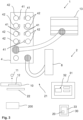
- FIG. 1 A central interconnection is shown schematically by means of a control cabinet 9, in order to connect this to a decentralized interconnection by means of spatially decentrally arranged electrical connection modules 4 of a machine 1 Fig. 2 to confront.
- a control cabinet 9 instead of connecting all devices 5 such as sensors and actuators directly to the control cabinet 9 as in Fig. 1 shown, can be used with decentralized interconnection Fig. 2 several connection modules 4 can be used.
- these enable the devices 5 to be coupled to a control device 8 such as a PLC.
- the connection modules 4 Decentralized and distributed in the vicinity of the devices 5.
- connection modules 4 thus only partially interconnect the devices 5, with the connection modules 4 together or, for example, one and/or more connection modules 4 each carrying out the entire interconnection via one and/or more hubs 6.
- a master module 3 can be connected upstream of several of the individual connection modules 4. It is also possible for the interconnection to be further subdivided using at least one hub 6.
- a system 2 which can be provided for a computer-assisted installation of spatially decentrally arranged electrical connection modules 4 of a machine 1.
- the system 2 can comprise a detection device 22, in particular a scanner 22 or a camera 22, for providing an identifier 11 of an installation element 10, preferably a cable 11 or a component 11.
- the system 2 can have at least one electrical connection module 4 for connection to the installation element 10 and other installation elements 10.
- a device 30 for data processing can also be part of the system 2, wherein this data processing device 30 can comprise means for carrying out the steps of a method 100 according to embodiments of the invention.
- the identifier 11 can be encoded in a machine-readable code 12 assigned to the installation element 10, in particular arranged on it, wherein the machine-readable code 12 is designed to be machine-readable by means of the detection device 22. It is thus possible for a user to scan the code 12 by means of the detection device 22 and thus to transmit the identifier 11 to the data processing device 30.
- connection modules 4 and at least one computer 30, 31 and/or a control device 8 can each be connected to one another via a bus system 21 for bidirectional communication, wherein the bidirectional communication can be provided based on a communication protocol for a fieldbus system, in particular based on a ProfiNet -, Ethernet/IP or 802.3 standards, and/or bidirectional communication can be provided wired via a bus system 21 or wirelessly via Bluetooth or WLAN, based on a standard according to IEEE 802.11 or based on a mobile telecommunications standard.
- the connection module 4 can also be connected to a power supply 13.
- a computer program 20 which includes instructions which, when the program is executed by a computer 30, cause the computer 30 to carry out the steps of the method 100 according to exemplary embodiments of the invention.
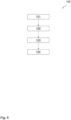
- Fig. 4 and 5 Method steps of the method 100 are visualized according to exemplary embodiments. Specifically, it is in Fig. 5 a method 100 for operating a connection module 4 during a computer-aided installation of a machine 1 is shown.
- the connection module 4 can be designed for a decentralized and modular connection of components - such as the installation elements 10 - of the machine 1.
- provision of an installation function of the connection module 4 for the installation of the machine 1 can be provided, wherein the installation function initiates an output of installation information to support the establishment of the connection of the components.
- the output of the installation information can include an initiation of an optical output.
- a second method step 102 provision of an operating function of the connection module 4 for operation of the installed machine 1 can be provided, wherein the operating function initiates an electrical output to the connected components.
- an installation mode can be initiated in the connection module 4, the operating function being deactivated and the installation function being activated.
- a test mode is carried out in order to check that the connection has been established properly.
- Initiating the optical output may initiate an activation of a Fig.3 illustrated display element 41 on the electrical component 4 in order to display a connection point 42, in particular a slot 42, for the installation element 10 to be connected in installation mode by the display element 41.
- initiating the output can comprise initiating a display of a connection point 42, in particular a slot 42, of the connection module 4 for the installation element 10 on a user interface 32 of a computer 31.
- the user interface 32 can visualize a digital twin of at least part of the machine 1, and preferably a mechanical and/or an electrical structure of the part of the machine 1.
- connection point 42 in particular a slot 42, of the connection module 4 for the installation element 10 by means of augmented reality and/or an output of the installation instructions as an instruction for the user to connect the installation element 10 to a specific connection point 42 of the connection module 4, wherein the connection point 42 is preferably determined based on the installation specification 200.
- an acoustic output of the installation instructions can also be provided so that a user can follow the installation instructions without seeing the computer 31. In this case, for example, an identifier of the connection module 4 and/or the corresponding connection point 42 is output verbally.
- the installation information includes an installation configuration and/or installation documentation, which is stored in a data storage 33 and/or transmitted to the connection module 4.
- the installation documentation can be used to document at least one of the following pieces of information: work steps of the user with additional information on the work steps such as processing time, which machine is being used, which user, for example which installer or fitter, carried out the activities and when, which component has been wired and/or cabled, has the assembly step been completed, which port/connection point was used, are there any open cables and what are the properties of the open cable, e.g. length, environmental parameters, e.g. temperature, humidity, current project status, protection class, e.g. IP67, the user, especially the worker, can also enter the reason for the plan deviation in the event of deviations from the plan.
- the installation documentation can be stored in a database, for example. A user can trigger the documentation with physical actions (key press, screen, double click) if necessary.
- an evaluation unit can be provided which evaluates the documented information, preferably the user's processing times for the respective work steps.
- An artificial intelligence method can also be used for this, which, for example, optimizes the results of the evaluation unit.
- the results show the user optimization potential in order to make a machine more efficient in the future, to optimize components or assemblies and to set up and Improve mining processes. Furthermore, the comments are taken into account in the event of deviations from the plan.
- connection module 4 that is not preconfigured or connected to a PLC. This avoids errors that can arise from using connection modules 4 that are externally identical but differently configured. Thanks to the communication capability of these components and the integration of all relevant information, the system can also be used to guide the user when installing the automation technology.
- the systematic collection and documentation of all relevant information for example the components used, the execution of installation and maintenance tasks or problems that have occurred, also leads to secure knowledge about the current system status.
- the automated collection and assignment of this information significantly speeds up the process and relieves human installers of the documentation task.
- the automated collection and storage of information to be documented can significantly reduce the risk of missing and/or incorrect documentation.
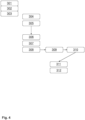
- Fig. 4 is a method 100 according to embodiments of the invention visualized with further details.
- a user can first carry out a user registration 301.
- the user can use a graphical user interface 32, which is provided by the computer 31.
- a project selection 302 can also be made via the user interface 32, through which, for example, an installation specification 200 is loaded for a desired project. This makes it possible to initiate a start 303 for instructions for the user to install the machine 1 using at least one installation instruction.
- a representation 304 of the last step carried out can first take place, for example the last installation instructions and/or another instruction for the installation.
- an identification 305 of an installation element 10 can be carried out by the user, for which the user uses, for example, a detection device 22 such as a hand scanner for scanning an identification means 12 on the installation element 10.
- the identifier 11 can then be determined and transmitted to the computer 31 and/or a device 30 for data processing.
- the installation specification 200 Based on the received Identifier 11 and the installation specification 200 can then identify the connection module 4 and the connection point 42 to which the installation element 10 is to be connected.
- the installation specification 200 includes, for example, a matrix in which various installation elements 10 are assigned to the connection modules 4.
- the installation instructions can then inform the user which of the connection modules 4 was identified. For this purpose, for example, a display element 41 on the connection module 4 lights up. This can be made possible by a signal transmission 306 from the data processing device 30 to the connection module 4. The user can then establish a connection 307 between the installation element 10 and the connection module 4. Based on the installation specification 200, a confirmation 308 of correct installation can be made. Subsequently, at least partially automated documentation 309 of the correct assembly and documentation 310 of the completion of the work step in the installation specification 200 may be possible. This can e.g. B. by a representation 311 in a machine overview with a green tick or, for example, by showing the affected connection in an electrical circuit diagram and presented to the user via the user interface 32. An identification of an installation element 312 can then be carried out again. By instructing the user, in particular the worker, when installing the electrical automation technology and by automatically checking whether a suitable component has been properly connected, error-free production of the system 2 can be ensured.
- the user can then establish a connection between the installation element and a device, such as an actuator and/or a hub and/or a sensor (not shown). Correct assembly can be confirmed using installation specification 200. Then, at least partially automated documentation of correct assembly and documentation of completion of the work step in installation specification 200 is possible. This can be done, for example, by displaying it in a machine overview with a green check mark or, for example, by displaying the connection in question in an electrical circuit diagram and presenting it to the user via user interface 32. These work steps correspond in principle to work steps 307 to 311.
- aspects have been described in connection with a device, it is clear that these aspects also represent a description of the corresponding method, wherein an element or device corresponds to a method step or a feature of a method step. Analogously, aspects described in connection with a method step also represent a description of a corresponding block or element or feature of a corresponding device.
- Embodiments of the invention may be implemented on a computer system.
- the computing system may be a local computing device (e.g., personal computer, laptop, tablet computer, or cell phone) with one or more processors and one or more storage devices, or a distributed computing system (e.g., a cloud computing system with one or more processors and one or more storage devices distributed in different locations, such as a local client and/or one or more remote server farms and/or data centers).
- the computer system may include any circuit or combination of circuits.
- the computer system may include one or more processors of any type.
- the term "processor" as used herein can refer to any type of computing circuit, e.g. B.
- a microprocessor a microcontroller, a CISC (Complex Instruction Set Computing) microprocessor, a RISC (Reduced Instruction Set Computing) microprocessor, a VLIW (Very Long Instruction Word) microprocessor, a graphics processor, a digital signal processor (DSP) , a multi-core processor, an FPGA (Field Programmable Gate Array), or any other type of processor or processing circuit.
- Other types of circuits that may be included in the computer system may be a custom circuit, an application specific integrated circuit (AsIC), or the like, such as: B. one or more circuits (e.g., a communications circuit) for use in wireless devices such as cell phones, tablet computers, laptop computers, two-way radios, and similar electronic systems.
- AsIC application specific integrated circuit
- the computer system may include one or more memory devices, which may include one or more memory elements suitable for the particular application, such as. B. a main memory in the form of a random access memory (RAM), one or more hard drives and / or one or more drives that process removable storage media such as compact disks (CD), flash memory cards, digital video disks (DVD) and the like.
- the computer system may also include a display device, one or more speakers, and a keyboard and/or a controller, which may include a mouse, trackball, touch screen, voice recognition device, or other device that allows a system user to enter information into the computer system to enter and receive information from it.
- Some or all of the method steps may be performed by (or using) a hardware device, such as: B. a processor, a microprocessor, a programmable computer or an electronic circuit. In some embodiments, some or more of the key process steps may be performed by such a device.
- embodiments of the invention may be implemented in hardware or in software.
- the implementation may be carried out using a non-transferable storage medium such as a digital storage medium, for example a floppy disk, a DVD, a Blu-Ray, a CD, a ROM, a PROM, an EPROM, an EEPROM or a FLASH memory on which electronically readable control signals are stored, which interact (or can interact) with a programmable computer system so that the respective method is carried out. Therefore, the digital storage medium can be computer readable.
- a digital storage medium for example a floppy disk, a DVD, a Blu-Ray, a CD, a ROM, a PROM, an EPROM, an EEPROM or a FLASH memory on which electronically readable control signals are stored, which interact (or can interact) with a programmable computer system so that the respective method is carried out. Therefore, the digital storage medium can be computer readable.
- Some embodiments of the invention include a data carrier with electronically readable control signals that are capable of cooperating with a programmable computer system to perform one of the methods described herein.
- embodiments of the present invention can be implemented as a computer program product with a program code, wherein the program code serves to carry out one of the methods when the computer program product is run on a computer.
- the program code can, for example, be stored on a machine-readable carrier.
- inventions include the computer program for performing one of the methods described herein stored on a machine-readable medium.
- one embodiment of the present invention is therefore a computer program with a program code for carrying out one of the methods described herein when the computer program runs on a computer.
- a further embodiment of the present invention is therefore a storage medium (or a data carrier or a computer-readable medium) on which the computer program for carrying out one of the methods described herein is stored when executed by a processor.
- the data carrier, the digital storage medium or the recorded medium is typically tangible and/or non-transferable.
- Another embodiment of the present invention is a device as described herein, including a processor and the storage medium.
- a further embodiment of the invention is therefore a data stream or a sequence of signals that represent the computer program for carrying out one of the methods described herein.
- the data stream or the signal sequence can, for example, be designed so that it can be transmitted via a data communication connection, for example via the Internet.
- Another embodiment includes a processing means, e.g., a computer or a programmable logic device, configured or adapted to perform any of the methods described herein.
- a processing means e.g., a computer or a programmable logic device, configured or adapted to perform any of the methods described herein.
- Another embodiment includes a computer on which the computer program for carrying out one of the methods described herein is installed.
- Another embodiment of the invention includes a device or system configured to transmit (e.g., electronically or optically) a computer program to a receiver for performing one of the methods described herein.
- the receiver can be, for example, a computer, a mobile device, a storage device or the like.
- the device or system may, for example, include a file server for transmitting the computer program to the recipient.
- a programmable logic device e.g., a field programmable gate array
- a field programmable gate array may work with a microprocessor to perform any of the methods described herein. In general, the methods are preferably performed by any hardware device.
Landscapes
- Engineering & Computer Science (AREA)
- General Engineering & Computer Science (AREA)
- Physics & Mathematics (AREA)
- General Physics & Mathematics (AREA)
- Theoretical Computer Science (AREA)
- Manufacturing & Machinery (AREA)
- Quality & Reliability (AREA)
- Automation & Control Theory (AREA)
- Human Computer Interaction (AREA)
- Health & Medical Sciences (AREA)
- Audiology, Speech & Language Pathology (AREA)
- General Health & Medical Sciences (AREA)
- Management, Administration, Business Operations System, And Electronic Commerce (AREA)
- Programmable Controllers (AREA)
- Electric Cable Installation (AREA)
Priority Applications (5)
| Application Number | Priority Date | Filing Date | Title |
|---|---|---|---|
| RS20250003A RS66466B1 (sr) | 2022-09-30 | 2022-11-10 | Postupak za pogon priključnog modula |
| EP23782220.0A EP4584651A1 (fr) | 2022-09-30 | 2023-09-28 | Procédé de fonctionnement d'un module de connexion |
| DE112023003166.5T DE112023003166A5 (de) | 2022-09-30 | 2023-09-28 | Verfahren zum Betreiben eines Verbindungsmoduls |
| CN202380068214.XA CN119998747A (zh) | 2022-09-30 | 2023-09-28 | 操作连接模块的方法 |
| PCT/EP2023/076841 WO2024068816A1 (fr) | 2022-09-30 | 2023-09-28 | Procédé de fonctionnement d'un module de connexion |
Applications Claiming Priority (1)
| Application Number | Priority Date | Filing Date | Title |
|---|---|---|---|
| EP22199162.3A EP4345554B1 (fr) | 2022-09-30 | 2022-09-30 | Procédé d'installation assistée par ordinateur de composants électriques d'une machine agencés de manière décentralisée dans l'espace |
Publications (3)
| Publication Number | Publication Date |
|---|---|
| EP4345558A1 true EP4345558A1 (fr) | 2024-04-03 |
| EP4345558C0 EP4345558C0 (fr) | 2024-11-20 |
| EP4345558B1 EP4345558B1 (fr) | 2024-11-20 |
Family
ID=83593821
Family Applications (6)
| Application Number | Title | Priority Date | Filing Date |
|---|---|---|---|
| EP22199162.3A Active EP4345554B1 (fr) | 2022-09-30 | 2022-09-30 | Procédé d'installation assistée par ordinateur de composants électriques d'une machine agencés de manière décentralisée dans l'espace |
| EP22205851.3A Active EP4345555B1 (fr) | 2022-09-30 | 2022-11-07 | Procédé de contrôle assisté par ordinateur et documentation d'une action d'installation d'un utilisateur pour installer des composants d'une machine agencés de manière spatiale |
| EP22205899.2A Active EP4345556B1 (fr) | 2022-09-30 | 2022-11-07 | Procédé d'installation assistée par ordinateur de composants agencés de manière décentralisée dans l'espace d'une machine |
| EP22205918.0A Active EP4345557B1 (fr) | 2022-09-30 | 2022-11-07 | Procédé d'installation assistée par ordinateur de composants électriques d'une machine agencés de manière décentralisée dans l'espace par plusieurs utilisateurs avec assistance spécifique à l'utilisateur |
| EP22206798.5A Active EP4345558B1 (fr) | 2022-09-30 | 2022-11-10 | Procédé de fonctionnement d'un module de connexion |
| EP23771888.7A Pending EP4581437A1 (fr) | 2022-09-30 | 2023-09-20 | Procédé pour l'installation assistée par ordinateur de composants électriques spatialement décentralisés d'une machine |
Family Applications Before (4)
| Application Number | Title | Priority Date | Filing Date |
|---|---|---|---|
| EP22199162.3A Active EP4345554B1 (fr) | 2022-09-30 | 2022-09-30 | Procédé d'installation assistée par ordinateur de composants électriques d'une machine agencés de manière décentralisée dans l'espace |
| EP22205851.3A Active EP4345555B1 (fr) | 2022-09-30 | 2022-11-07 | Procédé de contrôle assisté par ordinateur et documentation d'une action d'installation d'un utilisateur pour installer des composants d'une machine agencés de manière spatiale |
| EP22205899.2A Active EP4345556B1 (fr) | 2022-09-30 | 2022-11-07 | Procédé d'installation assistée par ordinateur de composants agencés de manière décentralisée dans l'espace d'une machine |
| EP22205918.0A Active EP4345557B1 (fr) | 2022-09-30 | 2022-11-07 | Procédé d'installation assistée par ordinateur de composants électriques d'une machine agencés de manière décentralisée dans l'espace par plusieurs utilisateurs avec assistance spécifique à l'utilisateur |
Family Applications After (1)
| Application Number | Title | Priority Date | Filing Date |
|---|---|---|---|
| EP23771888.7A Pending EP4581437A1 (fr) | 2022-09-30 | 2023-09-20 | Procédé pour l'installation assistée par ordinateur de composants électriques spatialement décentralisés d'une machine |
Country Status (11)
| Country | Link |
|---|---|
| EP (6) | EP4345554B1 (fr) |
| JP (1) | JP2025531559A (fr) |
| KR (1) | KR20250078551A (fr) |
| CN (1) | CN119948419A (fr) |
| DE (1) | DE112023003097A5 (fr) |
| ES (4) | ES3003784T3 (fr) |
| HU (5) | HUE070165T2 (fr) |
| MX (1) | MX2025003699A (fr) |
| PL (5) | PL4345554T3 (fr) |
| RS (1) | RS66443B1 (fr) |
| WO (1) | WO2024068390A1 (fr) |
Families Citing this family (3)
| Publication number | Priority date | Publication date | Assignee | Title |
|---|---|---|---|---|
| WO2025214879A1 (fr) * | 2024-04-10 | 2025-10-16 | Murrelektronik Gmbh | Procédé de délivrance d'une indication spatiale dans une installation industrielle |
| EP4632512A1 (fr) * | 2024-04-10 | 2025-10-15 | Murrelektronik GmbH | Procédé de sortie d'une indication spatiale dans une installation industrielle |
| EP4692969A1 (fr) * | 2024-08-09 | 2026-02-11 | Murrelektronik GmbH | Procédé de mise à jour d'une spécification d'installation dans une installation assistée par ordinateur d'une installation industrielle |
Citations (4)
| Publication number | Priority date | Publication date | Assignee | Title |
|---|---|---|---|---|
| WO2015028978A1 (fr) * | 2013-08-29 | 2015-03-05 | Umpi Elettronica - Societa' A Responsabilita' Limitata | Procédé et système permettant l'inspection et/ou la maintenance d'un panneau électrique au moyen de la réalité augmentée |
| DE102016120081A1 (de) * | 2016-10-21 | 2018-04-26 | Minimax Gmbh & Co. Kg | Verfahren zur Inbetriebnahme und/oder Wartung einer Brandmelder- und/oder Löschsteuerzentrale sowie Vorrichtung dafür |
| US20190123524A1 (en) * | 2016-05-02 | 2019-04-25 | Woehner Gmbh & Co., Kg Elektrotechnische Systeme | Method and System for Configuring a Switchgear Cabinet |
| WO2022020787A1 (fr) * | 2020-07-24 | 2022-01-27 | Schneider Electric USA, Inc. | Gestion d'équipement électrique |
Family Cites Families (11)
| Publication number | Priority date | Publication date | Assignee | Title |
|---|---|---|---|---|
| DE19849293A1 (de) | 1998-10-26 | 2000-04-27 | Ibtl Ing Buero Lang & Partner | Vorrichtung und Verfahren zum Erfassen von Meßwerten an einer Viehlzahl von Meßstellen eines Meßobjekts |
| EP1157315B1 (fr) * | 1999-03-02 | 2004-09-22 | Siemens Aktiengesellschaft | Systeme a realite amplifiee permettant l'utilisation d'appareils mobiles |
| DE102005044917A1 (de) * | 2005-09-20 | 2007-04-19 | As Tech Industrie- Und Spannhydraulik Gmbh | Anordnung zur Erfassung von Messgrößen in Schraubverbindungen |
| US7515981B2 (en) * | 2005-10-07 | 2009-04-07 | Ops Solutions Llc | Light guided assembly system |
| US20090192644A1 (en) * | 2008-01-30 | 2009-07-30 | Meyer Thomas J | Method and system for manufacturing an article using portable hand-held tools |
| WO2012109593A1 (fr) * | 2011-02-11 | 2012-08-16 | OPS Solutions, LLC | Système et procédé d'ensemble guidé de lumière |
| US20150227943A1 (en) * | 2014-02-07 | 2015-08-13 | Qvolve, LLC | System and Method for Documenting Regulatory Compliance |
| EP3244286B1 (fr) * | 2016-05-13 | 2020-11-04 | Accenture Global Solutions Limited | Installation d'un élément physique |
| EP3392987B1 (fr) * | 2017-04-21 | 2020-12-02 | Rittal GmbH & Co. KG | Procédé et système d'assistance automatisée d'un processus de raccordement, en particulier de composants disposés dans une armoire électrique ou sur un système de montage |
| CN109144251A (zh) * | 2018-07-31 | 2019-01-04 | 长沙拓扑陆川新材料科技有限公司 | 一种网络互连的可穿戴设备 |
| US11392112B2 (en) * | 2019-09-26 | 2022-07-19 | Rockwell Automation Technologies, Inc. | Virtual design environment |
-
2022
- 2022-09-30 EP EP22199162.3A patent/EP4345554B1/fr active Active
- 2022-09-30 HU HUE22199162A patent/HUE070165T2/hu unknown
- 2022-09-30 ES ES22199162T patent/ES3003784T3/es active Active
- 2022-09-30 RS RS20250087A patent/RS66443B1/sr unknown
- 2022-09-30 PL PL22199162.3T patent/PL4345554T3/pl unknown
- 2022-11-07 ES ES22205899T patent/ES3008946T3/es active Active
- 2022-11-07 EP EP22205851.3A patent/EP4345555B1/fr active Active
- 2022-11-07 EP EP22205899.2A patent/EP4345556B1/fr active Active
- 2022-11-07 HU HUE22205851A patent/HUE070184T2/hu unknown
- 2022-11-07 PL PL22205918.0T patent/PL4345557T3/pl unknown
- 2022-11-07 EP EP22205918.0A patent/EP4345557B1/fr active Active
- 2022-11-07 HU HUE22205918A patent/HUE072209T2/hu unknown
- 2022-11-07 PL PL22205851.3T patent/PL4345555T3/pl unknown
- 2022-11-07 HU HUE22205899A patent/HUE070349T2/hu unknown
- 2022-11-07 ES ES22205851T patent/ES3000808T3/es active Active
- 2022-11-07 PL PL22205899.2T patent/PL4345556T3/pl unknown
- 2022-11-10 PL PL22206798.5T patent/PL4345558T3/pl unknown
- 2022-11-10 ES ES22206798T patent/ES3000657T3/es active Active
- 2022-11-10 HU HUE22206798A patent/HUE071722T2/hu unknown
- 2022-11-10 EP EP22206798.5A patent/EP4345558B1/fr active Active
-
2023
- 2023-09-20 DE DE112023003097.9T patent/DE112023003097A5/de active Pending
- 2023-09-20 WO PCT/EP2023/075916 patent/WO2024068390A1/fr not_active Ceased
- 2023-09-20 JP JP2025518890A patent/JP2025531559A/ja active Pending
- 2023-09-20 KR KR1020257014385A patent/KR20250078551A/ko active Pending
- 2023-09-20 CN CN202380069038.1A patent/CN119948419A/zh active Pending
- 2023-09-20 EP EP23771888.7A patent/EP4581437A1/fr active Pending
-
2025
- 2025-03-27 MX MX2025003699A patent/MX2025003699A/es unknown
Patent Citations (4)
| Publication number | Priority date | Publication date | Assignee | Title |
|---|---|---|---|---|
| WO2015028978A1 (fr) * | 2013-08-29 | 2015-03-05 | Umpi Elettronica - Societa' A Responsabilita' Limitata | Procédé et système permettant l'inspection et/ou la maintenance d'un panneau électrique au moyen de la réalité augmentée |
| US20190123524A1 (en) * | 2016-05-02 | 2019-04-25 | Woehner Gmbh & Co., Kg Elektrotechnische Systeme | Method and System for Configuring a Switchgear Cabinet |
| DE102016120081A1 (de) * | 2016-10-21 | 2018-04-26 | Minimax Gmbh & Co. Kg | Verfahren zur Inbetriebnahme und/oder Wartung einer Brandmelder- und/oder Löschsteuerzentrale sowie Vorrichtung dafür |
| WO2022020787A1 (fr) * | 2020-07-24 | 2022-01-27 | Schneider Electric USA, Inc. | Gestion d'équipement électrique |
Also Published As
Similar Documents
| Publication | Publication Date | Title |
|---|---|---|
| EP4345558B1 (fr) | Procédé de fonctionnement d'un module de connexion | |
| EP3392987B1 (fr) | Procédé et système d'assistance automatisée d'un processus de raccordement, en particulier de composants disposés dans une armoire électrique ou sur un système de montage | |
| DE102011011587A1 (de) | Portunabhängiges topologisch geplantes Echtzeitnetzwerk | |
| EP4365807B1 (fr) | Procédé de test assisté par ordinateur d'un élément d'installation pour un environnement d'installation | |
| WO2024068816A1 (fr) | Procédé de fonctionnement d'un module de connexion | |
| WO2024068899A1 (fr) | Procédé de fourniture assistée par ordinateur d'une spécification d'adaptation pour une technologie d'installation électrotechnique | |
| EP4345703B1 (fr) | Procédé d'installation assistée par ordinateur de composants électriques d'une machine agencés de manière décentralisée dans l'espace | |
| EP4365691B1 (fr) | Procédé de détermination assistée par ordinateur de l'efficacité de l'installation de composants électriques d'une machine agencés de manière décentralisée dans l'espace | |
| WO2024068855A1 (fr) | Procédé d'installation assistée par ordinateur de composants électriques, disposés de manière décentralisée dans l'espace, d'une machine, par de multiples utilisateurs avec un support spécifique | |
| EP4345547A1 (fr) | Procédé d'installation assistée par ordinateur de composants électriques d'une machine agencés de manière décentralisée dans l'espace | |
| EP4584650A1 (fr) | Procédé d'installation assistée par ordinateur de composants spatialement décentralisés d'une machine | |
| EP4485097A1 (fr) | Procédé d'installation assistée par ordinateur de composants électriques d'une machine agencés de manière décentralisée dans l'espace | |
| WO2024068741A1 (fr) | Procédé de test et de documentation assistés par ordinateur d'une opération d'installation d'un utilisateur pour l'installation de composants spatialement décentralisés d'une machine | |
| EP4614257B1 (fr) | Procédé d'installation et/ou de mise en service et/ou de maintenance assisté par ordinateur et/ou de modernisation d'une installation industrielle | |
| EP4692969A1 (fr) | Procédé de mise à jour d'une spécification d'installation dans une installation assistée par ordinateur d'une installation industrielle | |
| DE102025107590A1 (de) | Verfahren zur computer-gestützten Installation und/oder Inbetriebnahme und/oder Wartung und/oder Modernisierung einer industriellen Anlage | |
| EP4345674A1 (fr) | Procédé de création assistée par ordinateur d'une topologie électrique décentralisée pour une machine | |
| EP4632512A1 (fr) | Procédé de sortie d'une indication spatiale dans une installation industrielle | |
| WO2025214879A1 (fr) | Procédé de délivrance d'une indication spatiale dans une installation industrielle | |
| EP4614245A1 (fr) | Procédé de dispositif assisté par ordinateur pour l'installation d'une installation industrielle | |
| WO2025186109A1 (fr) | Procédé de configuration d'élément maître et/ou de dispositif maître assistée par ordinateur |
Legal Events
| Date | Code | Title | Description |
|---|---|---|---|
| PUAI | Public reference made under article 153(3) epc to a published international application that has entered the european phase |
Free format text: ORIGINAL CODE: 0009012 |
|
| STAA | Information on the status of an ep patent application or granted ep patent |
Free format text: STATUS: THE APPLICATION HAS BEEN PUBLISHED |
|
| AK | Designated contracting states |
Kind code of ref document: A1 Designated state(s): AL AT BE BG CH CY CZ DE DK EE ES FI FR GB GR HR HU IE IS IT LI LT LU LV MC ME MK MT NL NO PL PT RO RS SE SI SK SM TR |
|
| STAA | Information on the status of an ep patent application or granted ep patent |
Free format text: STATUS: REQUEST FOR EXAMINATION WAS MADE |
|
| 17P | Request for examination filed |
Effective date: 20240405 |
|
| RBV | Designated contracting states (corrected) |
Designated state(s): AL AT BE BG CH CY CZ DE DK EE ES FI FR GB GR HR HU IE IS IT LI LT LU LV MC ME MK MT NL NO PL PT RO RS SE SI SK SM TR |
|
| GRAP | Despatch of communication of intention to grant a patent |
Free format text: ORIGINAL CODE: EPIDOSNIGR1 |
|
| GRAP | Despatch of communication of intention to grant a patent |
Free format text: ORIGINAL CODE: EPIDOSNIGR1 |
|
| STAA | Information on the status of an ep patent application or granted ep patent |
Free format text: STATUS: GRANT OF PATENT IS INTENDED |
|
| INTG | Intention to grant announced |
Effective date: 20240614 |
|
| GRAS | Grant fee paid |
Free format text: ORIGINAL CODE: EPIDOSNIGR3 |
|
| GRAA | (expected) grant |
Free format text: ORIGINAL CODE: 0009210 |
|
| STAA | Information on the status of an ep patent application or granted ep patent |
Free format text: STATUS: THE PATENT HAS BEEN GRANTED |
|
| RIN1 | Information on inventor provided before grant (corrected) |
Inventor name: KOHL, ULRICH Inventor name: ZELLER, PAUL Inventor name: PFESTORF, SEBASTIAN |
|
| AK | Designated contracting states |
Kind code of ref document: B1 Designated state(s): AL AT BE BG CH CY CZ DE DK EE ES FI FR GB GR HR HU IE IS IT LI LT LU LV MC ME MK MT NL NO PL PT RO RS SE SI SK SM TR |
|
| REG | Reference to a national code |
Ref country code: GB Ref legal event code: FG4D Free format text: NOT ENGLISH |
|
| REG | Reference to a national code |
Ref country code: CH Ref legal event code: EP |
|
| REG | Reference to a national code |
Ref country code: DE Ref legal event code: R096 Ref document number: 502022002172 Country of ref document: DE |
|
| REG | Reference to a national code |
Ref country code: IE Ref legal event code: FG4D Free format text: LANGUAGE OF EP DOCUMENT: GERMAN |
|
| U01 | Request for unitary effect filed |
Effective date: 20241212 |
|
| U07 | Unitary effect registered |
Designated state(s): AT BE BG DE DK EE FI FR IT LT LU LV MT NL PT RO SE SI Effective date: 20241223 |
|
| REG | Reference to a national code |
Ref country code: SK Ref legal event code: T3 Ref document number: E 45647 Country of ref document: SK |
|
| REG | Reference to a national code |
Ref country code: ES Ref legal event code: FG2A Ref document number: 3000657 Country of ref document: ES Kind code of ref document: T3 Effective date: 20250303 |
|
| REG | Reference to a national code |
Ref country code: GR Ref legal event code: EP Ref document number: 20250400096 Country of ref document: GR Effective date: 20250211 |
|
| PG25 | Lapsed in a contracting state [announced via postgrant information from national office to epo] |
Ref country code: HR Free format text: LAPSE BECAUSE OF FAILURE TO SUBMIT A TRANSLATION OF THE DESCRIPTION OR TO PAY THE FEE WITHIN THE PRESCRIBED TIME-LIMIT Effective date: 20241120 Ref country code: IS Free format text: LAPSE BECAUSE OF FAILURE TO SUBMIT A TRANSLATION OF THE DESCRIPTION OR TO PAY THE FEE WITHIN THE PRESCRIBED TIME-LIMIT Effective date: 20250320 |
|
| PG25 | Lapsed in a contracting state [announced via postgrant information from national office to epo] |
Ref country code: SM Free format text: LAPSE BECAUSE OF FAILURE TO SUBMIT A TRANSLATION OF THE DESCRIPTION OR TO PAY THE FEE WITHIN THE PRESCRIBED TIME-LIMIT Effective date: 20241120 |
|
| PLBE | No opposition filed within time limit |
Free format text: ORIGINAL CODE: 0009261 |
|
| STAA | Information on the status of an ep patent application or granted ep patent |
Free format text: STATUS: NO OPPOSITION FILED WITHIN TIME LIMIT |
|
| REG | Reference to a national code |
Ref country code: HU Ref legal event code: AG4A Ref document number: E071722 Country of ref document: HU |
|
| 26N | No opposition filed |
Effective date: 20250821 |
|
| REG | Reference to a national code |
Ref country code: CH Ref legal event code: U11 Free format text: ST27 STATUS EVENT CODE: U-0-0-U10-U11 (AS PROVIDED BY THE NATIONAL OFFICE) Effective date: 20251201 |
|
| PGFP | Annual fee paid to national office [announced via postgrant information from national office to epo] |
Ref country code: HU Payment date: 20251031 Year of fee payment: 4 |
|
| U20 | Renewal fee for the european patent with unitary effect paid |
Year of fee payment: 4 Effective date: 20251111 |
|
| PGFP | Annual fee paid to national office [announced via postgrant information from national office to epo] |
Ref country code: NO Payment date: 20251118 Year of fee payment: 4 |
|
| PGFP | Annual fee paid to national office [announced via postgrant information from national office to epo] |
Ref country code: TR Payment date: 20251105 Year of fee payment: 4 Ref country code: GR Payment date: 20251117 Year of fee payment: 4 |
|
| PGFP | Annual fee paid to national office [announced via postgrant information from national office to epo] |
Ref country code: CH Payment date: 20251201 Year of fee payment: 4 |
|
| PGFP | Annual fee paid to national office [announced via postgrant information from national office to epo] |
Ref country code: CZ Payment date: 20251029 Year of fee payment: 4 Ref country code: IE Payment date: 20251120 Year of fee payment: 4 |
|
| PGFP | Annual fee paid to national office [announced via postgrant information from national office to epo] |
Ref country code: PL Payment date: 20251031 Year of fee payment: 4 |
|
| PGFP | Annual fee paid to national office [announced via postgrant information from national office to epo] |
Ref country code: SK Payment date: 20251028 Year of fee payment: 4 |
|
| PGFP | Annual fee paid to national office [announced via postgrant information from national office to epo] |
Ref country code: RS Payment date: 20251106 Year of fee payment: 4 |
|
| PGFP | Annual fee paid to national office [announced via postgrant information from national office to epo] |
Ref country code: ES Payment date: 20251216 Year of fee payment: 4 |
|
| PG25 | Lapsed in a contracting state [announced via postgrant information from national office to epo] |
Ref country code: MC Free format text: LAPSE BECAUSE OF FAILURE TO SUBMIT A TRANSLATION OF THE DESCRIPTION OR TO PAY THE FEE WITHIN THE PRESCRIBED TIME-LIMIT Effective date: 20241120 |