EP4384716B1 - Bague de guidage à fente avec lubrification à recirculation et unité piston-cylindre la comprenant - Google Patents
Bague de guidage à fente avec lubrification à recirculation et unité piston-cylindre la comprenant Download PDFInfo
- Publication number
- EP4384716B1 EP4384716B1 EP22817993.3A EP22817993A EP4384716B1 EP 4384716 B1 EP4384716 B1 EP 4384716B1 EP 22817993 A EP22817993 A EP 22817993A EP 4384716 B1 EP4384716 B1 EP 4384716B1
- Authority
- EP
- European Patent Office
- Prior art keywords
- guide ring
- piston
- lubricant
- guide
- lubricant channel
- Prior art date
- Legal status (The legal status is an assumption and is not a legal conclusion. Google has not performed a legal analysis and makes no representation as to the accuracy of the status listed.)
- Active
Links
Images



Classifications
-
- F—MECHANICAL ENGINEERING; LIGHTING; HEATING; WEAPONS; BLASTING
- F16—ENGINEERING ELEMENTS AND UNITS; GENERAL MEASURES FOR PRODUCING AND MAINTAINING EFFECTIVE FUNCTIONING OF MACHINES OR INSTALLATIONS; THERMAL INSULATION IN GENERAL
- F16J—PISTONS; CYLINDERS; SEALINGS
- F16J15/00—Sealings
- F16J15/16—Sealings between relatively-moving surfaces
- F16J15/32—Sealings between relatively-moving surfaces with elastic sealings, e.g. O-rings
- F16J15/3204—Sealings between relatively-moving surfaces with elastic sealings, e.g. O-rings with at least one lip
- F16J15/3208—Sealings between relatively-moving surfaces with elastic sealings, e.g. O-rings with at least one lip provided with tension elements, e.g. elastic rings
-
- F—MECHANICAL ENGINEERING; LIGHTING; HEATING; WEAPONS; BLASTING
- F16—ENGINEERING ELEMENTS AND UNITS; GENERAL MEASURES FOR PRODUCING AND MAINTAINING EFFECTIVE FUNCTIONING OF MACHINES OR INSTALLATIONS; THERMAL INSULATION IN GENERAL
- F16J—PISTONS; CYLINDERS; SEALINGS
- F16J1/00—Pistons; Trunk pistons; Plungers
- F16J1/02—Bearing surfaces
-
- F—MECHANICAL ENGINEERING; LIGHTING; HEATING; WEAPONS; BLASTING
- F15—FLUID-PRESSURE ACTUATORS; HYDRAULICS OR PNEUMATICS IN GENERAL
- F15B—SYSTEMS ACTING BY MEANS OF FLUIDS IN GENERAL; FLUID-PRESSURE ACTUATORS, e.g. SERVOMOTORS; DETAILS OF FLUID-PRESSURE SYSTEMS, NOT OTHERWISE PROVIDED FOR
- F15B15/00—Fluid-actuated devices for displacing a member from one position to another; Gearing associated therewith
- F15B15/08—Characterised by the construction of the motor unit
- F15B15/14—Characterised by the construction of the motor unit of the straight-cylinder type
- F15B15/1423—Component parts; Constructional details
- F15B15/1447—Pistons; Piston to piston rod assemblies
- F15B15/1452—Piston sealings
-
- F—MECHANICAL ENGINEERING; LIGHTING; HEATING; WEAPONS; BLASTING
- F15—FLUID-PRESSURE ACTUATORS; HYDRAULICS OR PNEUMATICS IN GENERAL
- F15B—SYSTEMS ACTING BY MEANS OF FLUIDS IN GENERAL; FLUID-PRESSURE ACTUATORS, e.g. SERVOMOTORS; DETAILS OF FLUID-PRESSURE SYSTEMS, NOT OTHERWISE PROVIDED FOR
- F15B15/00—Fluid-actuated devices for displacing a member from one position to another; Gearing associated therewith
- F15B15/08—Characterised by the construction of the motor unit
- F15B15/14—Characterised by the construction of the motor unit of the straight-cylinder type
- F15B15/1423—Component parts; Constructional details
- F15B15/1457—Piston rods
- F15B15/1461—Piston rod sealings
-
- F—MECHANICAL ENGINEERING; LIGHTING; HEATING; WEAPONS; BLASTING
- F16—ENGINEERING ELEMENTS AND UNITS; GENERAL MEASURES FOR PRODUCING AND MAINTAINING EFFECTIVE FUNCTIONING OF MACHINES OR INSTALLATIONS; THERMAL INSULATION IN GENERAL
- F16J—PISTONS; CYLINDERS; SEALINGS
- F16J1/00—Pistons; Trunk pistons; Plungers
- F16J1/08—Constructional features providing for lubrication
-
- F—MECHANICAL ENGINEERING; LIGHTING; HEATING; WEAPONS; BLASTING
- F16—ENGINEERING ELEMENTS AND UNITS; GENERAL MEASURES FOR PRODUCING AND MAINTAINING EFFECTIVE FUNCTIONING OF MACHINES OR INSTALLATIONS; THERMAL INSULATION IN GENERAL
- F16J—PISTONS; CYLINDERS; SEALINGS
- F16J15/00—Sealings
- F16J15/16—Sealings between relatively-moving surfaces
- F16J15/32—Sealings between relatively-moving surfaces with elastic sealings, e.g. O-rings
- F16J15/3204—Sealings between relatively-moving surfaces with elastic sealings, e.g. O-rings with at least one lip
- F16J15/3232—Sealings between relatively-moving surfaces with elastic sealings, e.g. O-rings with at least one lip having two or more lips
-
- F—MECHANICAL ENGINEERING; LIGHTING; HEATING; WEAPONS; BLASTING
- F16—ENGINEERING ELEMENTS AND UNITS; GENERAL MEASURES FOR PRODUCING AND MAINTAINING EFFECTIVE FUNCTIONING OF MACHINES OR INSTALLATIONS; THERMAL INSULATION IN GENERAL
- F16J—PISTONS; CYLINDERS; SEALINGS
- F16J15/00—Sealings
- F16J15/16—Sealings between relatively-moving surfaces
- F16J15/32—Sealings between relatively-moving surfaces with elastic sealings, e.g. O-rings
- F16J15/324—Arrangements for lubrication or cooling of the sealing itself
-
- F—MECHANICAL ENGINEERING; LIGHTING; HEATING; WEAPONS; BLASTING
- F16—ENGINEERING ELEMENTS AND UNITS; GENERAL MEASURES FOR PRODUCING AND MAINTAINING EFFECTIVE FUNCTIONING OF MACHINES OR INSTALLATIONS; THERMAL INSULATION IN GENERAL
- F16J—PISTONS; CYLINDERS; SEALINGS
- F16J15/00—Sealings
- F16J15/16—Sealings between relatively-moving surfaces
- F16J15/32—Sealings between relatively-moving surfaces with elastic sealings, e.g. O-rings
- F16J15/3268—Mounting of sealing rings
- F16J15/3272—Mounting of sealing rings the rings having a break or opening, e.g. to enable mounting on a shaft otherwise than from a shaft end
-
- F—MECHANICAL ENGINEERING; LIGHTING; HEATING; WEAPONS; BLASTING
- F16—ENGINEERING ELEMENTS AND UNITS; GENERAL MEASURES FOR PRODUCING AND MAINTAINING EFFECTIVE FUNCTIONING OF MACHINES OR INSTALLATIONS; THERMAL INSULATION IN GENERAL
- F16J—PISTONS; CYLINDERS; SEALINGS
- F16J15/00—Sealings
- F16J15/56—Other sealings for reciprocating rods
Definitions
- the piston In piston-cylinder units, the piston (or piston rod) is usually guided along the cylinder by one or more guide rings.
- the guide rings prevent metal-to-metal contact between the two components and absorb and compensate for radial forces. The latter is also essential for reliable sealing performance and the longevity of the sealing elements used between the moving components.
- the guide rings are usually slotted to facilitate their installation.
- the slotted guide rings used in practice are available in a wide variety of materials to ensure the best possible wear resistance for each application.
- the guide rings can be designed for different operating times and the different radial forces to be absorbed during operation.
- Specially modified thermoplastic materials such as polytetrafluoroethylene (PTFE), polyamides (PA), or polyoxymethylene (POM) are often used for this purpose.
- PTFE polytetrafluoroethylene
- PA polyamides
- POM polyoxymethylene
- Other aspects that the guide rings must meet include the lowest possible coefficient of friction when paired with the material of the machine part that dynamically contacts the guide ring, anti-adhesive behavior, a suitable operating temperature range, chemical resistance if necessary, and the greatest possible resistance to aging.
- the guide rings Due to manufacturing tolerances of the guide rings themselves, as well as of the machine parts moving relative to each other, the guide rings available on the market can lead to malfunctions such as increased wear or a pronounced slip-stick effect, or in extreme cases, even guide ring failure. In this respect, adequate lubrication of the guide ring in the area of its contact zone(s) with the machine part dynamically resting against the guide ring is crucial.
- a profiled guide band for piston-cylinder units is known, which is arranged in a ring shape during operation.
- the guide band has a guide side with several lubricant channels running parallel to one another, which are arranged diagonally with respect to the side flanks of the guide band or the guide ring formed from it.
- the lubricant channels therefore extend partly in the axial direction from one side flank to the other and have a considerable difference in length.
- DE 37 31 158 A1 discloses a slotted guide ring for a piston-cylinder unit, which has at least one lubricant channel on its guide side, which extends in the circumferential direction of the guide ring from the first free end section to the second free end section of the guide ring and which is open on both sides towards the axial clearance gap between the two end sections of the guide ring.
- the problem concerning the guide ring is solved by a guide ring having the features specified in claim 1.
- the piston-cylinder unit according to the invention has the features specified in claim 8.
- Preferred developments of the invention are specified in the subclaims and in the description.
- the guide ring according to the invention is intended for use in a piston-cylinder unit and consists partially or completely of a viscoelastically deformable base material.
- the guide ring has a guide side that faces inwards or outwards in a direction radial to the central axis of the guide ring and serves for dynamically contacting and guiding a machine part, in particular the cylinder of the piston-cylinder unit.
- the guide ring further comprises a rear side that faces away from the guide side in the radial direction and serves for statically contacting support of the guide ring on another machine part, in particular the piston (or a piston rod) of the piston-cylinder unit.
- the term "piston” in this case also includes a piston rod known per se.
- a first and a second free end section of the guide ring are arranged spaced apart from one another in the circumferential direction of the guide ring, forming an axial through gap.
- the end faces of the free end sections are arranged parallel or substantially parallel to one another, wherein the two end faces, in their projection onto the central axis, enclose an acute angle ⁇ with the central axis of 15° ⁇ ⁇ ⁇ 75°, in particular 25° ⁇ ⁇ ⁇ 60°.
- each lubricant channel is formed between each two immediately adjacent annular beads. Each lubricant channel is thus bounded on both sides in the axial direction by one of the annular beads.
- the guide ring can in particular have exactly one, two or exactly three lubricant channels.
- the guide ring can also have more than three lubricant channels. According to the invention, each lubricant channel extends in the circumferential direction of the guide ring from the first free end section to the second free end section and is open on both sides towards the through gap of the guide ring. In other words, each lubricant channel of the guide ring opens into the aforementioned axial through gap.
- the guide ring When installed, the guide ring, with its annular beads, provides several linear or ring-shaped load-bearing surfaces or contact zones for the machine part of the piston-cylinder unit guided by them.
- the spaced-apart linear contact zones of the guide ring enable particularly low-friction guidance of the two machine parts relative to each other. Furthermore, this, along with the viscoelastic material of the guide ring, counteracts undesirable stick-slip behavior.
- each lubricant channel of the guide ring can be used to achieve improved lubrication of the dynamic contact zones formed by the annular beads for the machine part guided against the guide ring in a sliding clearance fit over the entire or essentially entire circumferential extent of the guide ring, and thus to improve the service life of the guide ring. Because at least one lubricant channel or each lubricant channel is open at both ends only towards the front sides of the two free end sections, this results in a particularly uniform thermal distribution during operation. Cooling and lubrication of the guide ring in the area of the contact zones of the annular beads on the sliding surface of the machine part that dynamically contacts the guide ring. Furthermore, the production of the guide ring is also simplified.
- the viscoelastic deformability of the guide ring enables dynamic adjustment of the size of the respective (annular) load-bearing surface/contact zone to a radial force acting on the guide ring when installed.
- the size of the respective contact zone of the guide ring thus increases with an increased radial force acting locally on the guide ring, and vice versa.
- this results in an overall flattened progression of the contact pressure (surface pressure in N/mm2) between the sliding surface of the machine part dynamically sliding along the guide ring and the guide ring as the radial load on the guide ring increases.
- each lubricant channel has a wave-like configuration in the circumferential direction. This design allows for particularly effective cooling of the guide ring and flushing of each lubricant channel.
- the free end sections preferably each have a flow funnel for the lubricant, into which each of the lubricant channels of the guide ring opens.
- Each of these flow funnels widens towards the axial through-gap. This allows, on the one hand, a particularly large inlet opening for the lubricant channels to be provided.
- a sufficiently large Back pressure of the lubricant flowing into the flow funnel is built up. This ensures that the lubricant, derived from the relative movement of the two machine parts (piston/cylinder), is pressed into each lubricant channel during operation at a flow velocity sufficient for flushing, lubrication, and cooling of the dynamic contact zones formed by the annular beads. Contaminants contained in the lubricant channel can thus be reliably removed or flushed out of the lubricant channel during operation.
- each lubricant channel can have a wave-shaped configuration in the circumferential direction. This design allows for particularly effective cooling of the guide ring and flushing of each lubricant channel.
- Each lubricant channel can have a static constriction or a dynamic constriction of its flow cross-section at at least one circumferential position of the guide ring.
- a static constriction exists when this has a flow-through cross-section that remains unchanged during operation of the guide ring.
- the lubricant channel has a variable flow-through cross-section depending on the lubricant pressure or volume flow within the lubricant channel. This can be achieved, for example, by an inflow element that is flexibly deformable or flexibly hinged to the guide ring (through which the lubricant can flow).
- the inflow element can, for example, be designed in the form of an elastically deformable tongue that is integrally formed with the rest of the guide ring and which projects into the lubricant channel.
- the tongue is preferably bidirectionally deflectable/deformable in the circumferential direction of the guide ring.
- the inflow element can also be a ball or the like, which projects into the lubricant channel and which can be moved (at least partially) out of the lubricant channel in an axial or radial direction against the force of a spring element or the material of the guide ring.
- the guide ring With its annular beads arranged on the guide side, the guide ring provides several linear or ring-shaped load-bearing surfaces or contact zones for the machine part of the piston-cylinder unit guided by them when installed.
- the spaced-apart linear load-bearing surfaces of the guide ring enable particularly low-friction guidance of the two machine parts relative to each other. Furthermore, this, along with the viscoelastic material of the guide ring, counteracts undesirable stick-slip behavior.
- each of the annular beads preferably has a vertex with side flanks which slope down on both sides of the vertex in a radial direction relative to the central axis of the guide ring.
- the back of the guide ring can be cylindrical in its unloaded cross-section. This allows the guide ring to fully support itself against a cylindrical groove base of a retaining groove in a machine part.
- the rear side in the cross-section of the unloaded or also the installed guide ring can be designed in a wave- or zigzag-shaped manner, ie, it can have several radial projections. These radial projections preferably extend in a manner corresponding to the annular beads in the circumferential direction of the guide ring, each over the the entire or substantially the entire circumferential extent of the guide ring.
- the annular beads and the radial projections can be arranged radially aligned with one another in the cross-section of the guide ring. This allows the response of the guide ring to changing radial loads on the guide ring to be easily adjusted through the geometric design of the radial projections.
- one and the same guide ring can be used as a so-called rod or piston rod guide ring or even as a piston ring. In the former case, the guide ring is arranged in the retaining groove of the cylinder or housing of the (piston) rod, and in the latter case, the guide ring is arranged in the retaining groove of the piston. This increases the range of applications of the guide ring and reduces provisioning and storage costs.
- the annular beads and the radial projections are preferably identical in size and geometry.
- the guide ring can be designed in a multi-component construction.
- the guide ring can in particular comprise a known support or reinforcement insert, preferably made of metal or a technical ceramics. This is advantageous for the range of applications of the guide ring.
- the annular beads can comprise a harder material with a preferably lower coefficient of friction compared to the base material of the guide ring or to the rest of the guide ring.
- the piston-cylinder unit comprises a first machine part in the form of a piston or piston rod and a second machine part in the form of a cylinder, in which the first machine part is guided for reciprocating movement along a movement axis.
- At least one guide ring according to the above embodiments is arranged in a retaining groove of one of the two machine parts. The piston is supported and guided on the cylinder via this guide ring, forming a bearing gap between the piston and cylinder in a sliding-play positive engagement.
- a lubricant arranged in the bearing gap flows into the at least one lubricant channel of the guide ring via one of the two free end sections of the guide ring during a forward stroke movement of the first machine part and via the respective other of the two free end sections of the guide ring during a return stroke movement of the first machine part.
- the lubricant is thus introduced into the at least one lubricant channel of the guide ring and flowed through it as a result of the axial relative movement of the two machine parts.
- the piston-cylinder unit can be used for pneumatic or hydraulic applications.
- a media-actuated deactivation of the dynamic constriction of the flow cross-section of the at least one lubricant channel is effected when a defined back pressure of the lubricant in the at least one flow channel is reached or exceeded.
- the constriction can achieve turbulent flow within the lubricant channel. which enables particularly efficient mixing of the lubricant and improved removal of contaminants introduced into the lubricant channel.
- the guide ring is preferably positioned with an axial clearance in the retaining groove relative to the movement axis. This ensures simplified assembly and less prone to failure of the piston-cylinder unit.
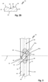
- FIG. 1 A piston-cylinder unit 10 is shown in a partial sectional view.
- the piston-cylinder unit 10 has a first machine part 12 in the form of a piston and a second machine part 14 in the form of a cylinder.
- the piston 12 is guided in the cylinder 14 so as to be movable back and forth along a movement axis L.
- the term "piston” in this case also refers to a piston rod, which is known per se.
- a sealing ring 18 serves to provide fluid-tight and pressure-tight sealing of a bearing gap 16 formed between the piston and the cylinder.
- the sealing ring 18 dynamically seals against a sliding surface 20 of the cylinder formed by the inner wall of the cylinder.
- the sealing ring 18 can be provided with a preload element 22.
- the first machine part 12 is provided here with two guide rings 24 , via which the first machine part 12 is guided along the sliding surface 20 of the second machine part 14.
- the two in Fig. 1 The guide rings 24 shown are each arranged in a circumferential retaining groove 26 of the first machine part 12.
- Each guide ring 24 has a dynamically guiding front or guide side 28 and a rear side 30 which are connected to one another via side flanks 32 of the guide ring 24.
- the guide side 28 serves for the dynamic contacting of the respective guide ring 24 on the cylinder 14. Accordingly, the guide side 28 points outwards in a radial direction to the central axis Z of the guide ring 24.
- the central axis Z of the guide ring 24 coincides with the movement axis L of the piston-cylinder unit 10 in the assembled state of the guide ring 24 (cf. e.g. Fig. 1 ) together or substantially together.
- the contact zones of each guide ring 24 with the sliding surface 20 are designated C.
- the rear side 30 of the respective guide ring 24 serves to provide static contact support for the guide ring 28 on the groove base of the machine part 12, 14 having the retaining groove 26, here for example the Fig. 1 shown piston 12.
- the guide ring 24 is shown in a cut-out perspective detail.
- the guide ring 24 is slotted.
- the guide ring 24 has a first and a second end section 34, 36 in the circumferential direction, which are arranged at a distance from one another to form an axial through gap 38.
- the slotted shape of the guide ring 24 simplifies its assembly.
- the two end sections 34, 36 have mutually facing end faces 40, 42 , which are arranged parallel to one another or substantially parallel to one another.
- the end faces 40, 42 in their projection onto the central axis Z, are aligned with the central axis Z (cf. Fig. 1 ) each form an acute angle ⁇ with 15° ⁇ ⁇ ⁇ 75°.
- the angle ⁇ can be calculated according to Fig. 1 in particular 40°.
- each guide ring 24 must occasionally absorb high radial loads and is inevitably subject to wear, not least due to friction-related mechanical and thermal loads. Due to manufacturing tolerances of conventional guide rings themselves, but also of the machine parts moving relative to one another, malfunctions can occur, such as increased wear, an undesirable slip-stick effect, or in extreme cases, This can even lead to premature failure of conventional guide rings.
- Each guide ring 24 therefore has a plurality of annular beads 44 formed on/on its guide side 28, each of which is arranged at a distance from one another in an axial direction relative to the central axis Z of the guide ring 24.
- a lubricant channel 46 is delimited on both sides in the axial direction by the annular beads 44.
- the lubricant channel 46 extends in the circumferential direction of the guide ring 24 from the first free end section 34 to the second free end section 36 and is open on both sides towards the axial through gap 38.
- the lubricant channel 46 is therefore fluidically connected to the axial through gap 38 at both ends.
- a lubricant S arranged in the bearing or sealing gap 16 is thus, during a forward stroke movement V of the first machine part 12 and during a return stroke movement R of the first machine part 12, alternately drawn or pressed into the lubricant channel 46 via the respective free end section 34, 36 of the guide ring 24, the end face 40, 42 of which is opposite to the respective direction of movement of the first machine part 12 in the axial direction.
- Each lubricant channel 46 of the guide ring 24 can widen towards the end face 40, 42 of the respective end section 34, 36 and thus form a flow funnel 48 or open into a flow funnel 48 of the end sections 34, 36.
- This allows, on the one hand, a particularly large inlet opening 46a to be provided for each of the lubricant channels 46.
- this allows, during a forward stroke movement V as well as during a return stroke movement R of the piston ( Fig. 1 ) a back pressure of the respective Flow funnel 48 of the incoming lubricant can be built up.
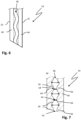
- the guide ring can be Fig. 4 on its guide side 28 also have more than two, in particular three, annular beads 44. Two of the annular beads 44 define a lubricant channel 46 between each other in pairs. The two lubricant channels 46 preferably together form one of the lubricant channels described in connection with Fig. 3 The lubricant channels 46 flow out of or into the flow funnels explained above. It should be noted that the lubricant channels 46 can be fluidically connected to one another by one or more axial connecting channels 50 .
- the guide ring 24 can be adjusted according to the Fig. 5 As shown in the sectional view, the guide ring 24 can also have a rear side 30 corrugated in the axial direction with radial projections 52. This design allows manufacturing tolerances of both machine parts and the guide ring 24 to be compensated particularly effectively.
- the rear-side radial projections 52 of the guide ring 24 can be arranged radially aligned with the annular beads 44 on the front side of the guide ring. They can also match the annular beads 44 in terms of their geometry and size.
- the lubricant channel 46 can have a particularly uniform, undulating course in the circumferential direction. This design provides particularly efficient lubrication of the contact zone C of the annular beads 44 with the associated sliding surface 20 of the cylinder 12.
- Each lubricant channel 46 of the guide ring 24 can have one or more static and/or dynamically variable constrictions 54 (of its free cross-section through which the lubricant can flow).
- Each constriction 54 can be formed, in particular, by an inflow element 56, for example in the form of one or more wall projections, as shown in Fig. 7 is shown.
- the inflow element 56 can, for example, be flexibly deformable or arranged on the guide ring so that it can be flexibly deflected.
- the inflow element 56 can be deflected—lubricant-actuated—in the direction of the central axis Z of the guide ring 24.
- Such constrictions 54 can generate a back pressure of the lubricant within the lubricant channel 46, thus allowing the lubrication to be locally adjusted as needed.
- the annular beads 44 and/or the rear radial projections 52 of the guide ring 24 may comprise a material which has a smaller modulus of elasticity or a smaller coefficient of friction compared to the material of the remaining guide ring 24.
- the guide ring 24 can be made at least partially or entirely of an elastomer, such as ethylene propylene diene rubber (EPDM) or fluororubber (FKM), as well as additives familiar to those skilled in the art.
- EPDM ethylene propylene diene rubber
- FKM fluororubber
- PA polyamide
- PEEK polyetheretherketone
- the guide ring 24 can have a conventional reinforcing or supporting insert, for example in the form of a supporting ring.
- the reinforcing or supporting insert can be made, in particular, of metal, a technical ceramic, or a composite material, e.g., one containing carbon fiber.
- the guide ring can also be pre-assembled in a cartridge and inserted together with the cartridge into a retaining groove of the piston or cylinder.
Landscapes
- Engineering & Computer Science (AREA)
- General Engineering & Computer Science (AREA)
- Mechanical Engineering (AREA)
- Chemical & Material Sciences (AREA)
- Combustion & Propulsion (AREA)
- Physics & Mathematics (AREA)
- Fluid Mechanics (AREA)
- Pistons, Piston Rings, And Cylinders (AREA)
- Bearings For Parts Moving Linearly (AREA)
Claims (9)
- Bague de guidage fendue (24) pour une unité piston-cylindre (10), constituée partiellement ou entièrement d'un matériau de base déformable de manière viscoélastique,- avec une face de guidage (28) qui est dirigée vers l'intérieur ou vers l'extérieur dans une direction radiale par rapport à l'axe central Z de la bague de guidage (24) et qui sert à l'installation avec mise en contact dynamique au niveau d'une pièce de machine (12, 14), et- avec une face arrière (30) qui se détourne de la face de guidage (28) dans la direction radiale et qui sert au soutien avec mise en contact statique de la bague de guidage (24),- avec une première section d'extrémité libre (34) et une deuxième section d'extrémité libre (36) qui sont agencées de manière espacée l'une de l'autre dans la direction circonférentielle de la bague de guidage en formant un interstice de passage (38) axial et dont les faces avant (40, 42) sont agencées parallèlement l'une à l'autre ou de manière essentiellement parallèle l'une à l'autre,
les faces avant (40, 42) faisant avec l'axe central Z un angle aigu a compris entre 15° et 75° lorsqu'elles sont projetées sur l'axe central Z ;- avec plusieurs bourrelets annulaires (44) formés au niveau de la face de guidage (28) et respectivement agencés de manière espacée les uns des autres dans une direction axiale par rapport à l'axe central Z de la bague de guidage (24),- avec au moins un canal de lubrifiant (46) qui est délimité des deux côtés dans la direction axiale par respectivement deux des bourrelets annulaires (44),caractérisée en ce que
le canal de lubrifiant (46) s'étendant dans la direction circonférentielle de la bague de guidage (24) depuis la première section d'extrémité libre (34) jusqu'à la deuxième section d'extrémité libre (36) et étant ouvert des deux côtés par rapport à l'interstice de passage axial (38),
le au moins un canal de lubrifiant (46) présente une forme ondulée dans la direction circonférentielle. - Bague de guidage (24) selon la revendication 1, caractérisée en ce que les deux sections d'extrémité libres (34, 36) présentent respectivement un entonnoir d'écoulement (48) dans lequel débouche chacun des canaux de lubrifiant (46).
- Bague de guidage (24) selon l'une quelconque des revendications précédentes, caractérisée en ce que le au moins un canal de lubrifiant (46) présente un rétrécissement statique ou dynamique (54) au niveau d'au moins une position circonférentielle de la bague de guidage (24).
- Bague de guidage (24) selon l'une quelconque des revendications précédentes, caractérisée en ce que la face arrière (30) présente une forme ondulée ou en zigzag en coupe transversale de la bague de guidage (24) non sollicitée et présente plusieurs saillies radiales (52) qui s'étendent dans la direction circonférentielle de la bague de guidage (24) respectivement sur la totalité ou essentiellement la totalité de l'extension circonférentielle de la bague de guidage (24).
- Bague de guidage (24) selon la revendication 4, caractérisée en ce que les bourrelets annulaires (44) et les saillies radiales (52) sont agencés de manière alignée les uns par rapport aux autres dans une direction radiale.
- Bague de guidage (24) selon l'une quelconque des revendications précédentes, caractérisée en ce que les bourrelets annulaires (44) comprennent un matériau plus dur avec un coefficient de frottement de manière préférée plus faible que le matériau de base de la bague de guidage (24).
- Unité piston-cylindre (10), comprenant- une première pièce de machine (12) sous la forme d'une tige de piston ou d'un piston ;- une deuxième pièce de machine (14) sous la forme d'un cylindre, au sein de laquelle la première pièce de machine (12) est guidée de manière à pouvoir effectuer un mouvement de va-et-vient le long d'un axe de déplacement (L) ;- au moins une bague de guidage (24) selon l'une quelconque des revendications précédentes 1 à 6, qui est agencée dans une rainure de retenue (26) de l'une des deux pièces de machine (12, 14) et par l'intermédiaire de laquelle la respectivement autre pièce de machine (12, 14) est soutenue et guidée avec constitution d'un interstice de palier (16) formé entre les deux pièces de machine (12, 14) avec verrouillage par complémentarité de forme et jeu de glissement, de telle manière qu'un lubrifiant S placé dans l'interstice de palier (16) s'écoule dans le au moins un canal de lubrifiant (46) de la bague de guidage (24) lors d'un mouvement d'avance V de la première pièce de machine (12) au-dessus de l'une des sections d'extrémité libres (34, 36) de la bague de guidage (24) et lors d'un mouvement de recul de la première pièce de machine (12) au-dessus de l'autre section d'extrémité (34, 36) respective de la bague de guidage (24).
- Unité piston-cylindre (10) selon la revendication 7, lorsque la revendication 7 dépend de la revendication 3, caractérisée en ce que le rétrécissement dynamique (56) du canal de lubrifiant (24) peut être réduit ou désactivé en cours de fonctionnement grâce au lubrifiant s'écoulant à travers le canal de lubrifiant.
- Unité piston-cylindre (10) selon la revendication 7 ou 8, caractérisée en ce que la bague de guidage (24) est agencée par rapport à l'axe de déplacement (L) avec de l'air axial dans la rainure de retenue (26).
Applications Claiming Priority (2)
| Application Number | Priority Date | Filing Date | Title |
|---|---|---|---|
| DE102021213007.0A DE102021213007B3 (de) | 2021-11-18 | 2021-11-18 | Geschlitzter führungsring mit umlaufschmierung und kolben-zylinder-einheit mit einem solchen |
| PCT/EP2022/082023 WO2023088913A1 (fr) | 2021-11-18 | 2022-11-15 | Bague de guidage à fente avec lubrification à recirculation et unité piston-cylindre la comprenant |
Publications (3)
| Publication Number | Publication Date |
|---|---|
| EP4384716A1 EP4384716A1 (fr) | 2024-06-19 |
| EP4384716B1 true EP4384716B1 (fr) | 2025-04-30 |
| EP4384716C0 EP4384716C0 (fr) | 2025-04-30 |
Family
ID=83899101
Family Applications (1)
| Application Number | Title | Priority Date | Filing Date |
|---|---|---|---|
| EP22817993.3A Active EP4384716B1 (fr) | 2021-11-18 | 2022-11-15 | Bague de guidage à fente avec lubrification à recirculation et unité piston-cylindre la comprenant |
Country Status (6)
| Country | Link |
|---|---|
| US (1) | US12398804B2 (fr) |
| EP (1) | EP4384716B1 (fr) |
| CN (1) | CN118251549B (fr) |
| DE (1) | DE102021213007B3 (fr) |
| TW (1) | TWI842165B (fr) |
| WO (1) | WO2023088913A1 (fr) |
Families Citing this family (1)
| Publication number | Priority date | Publication date | Assignee | Title |
|---|---|---|---|---|
| CN115789007A (zh) * | 2022-11-28 | 2023-03-14 | 江苏徐工工程机械研究院有限公司 | 一种液压缸导向环及其制备方法 |
Family Cites Families (24)
| Publication number | Priority date | Publication date | Assignee | Title |
|---|---|---|---|---|
| DE299395C (fr) | ||||
| US2489715A (en) * | 1944-11-18 | 1949-11-29 | Clayton Mark & Company | Packing |
| GB918013A (en) | 1958-06-03 | 1963-02-13 | Armstrong Patents Co Ltd | Improvements in or relating to shaft or rod seals |
| DE2235987A1 (de) | 1972-07-21 | 1974-01-31 | Linde Ag | Kolben fuer hubkolbenmaschine, insbesondere fuer trockenlaeufer |
| JPS4987945A (fr) * | 1972-12-11 | 1974-08-22 | ||
| DE7535535U (de) * | 1975-11-08 | 1977-04-28 | Robert Bosch Gmbh, 7000 Stuttgart | Arbeitszylinder |
| US4334688A (en) | 1980-05-08 | 1982-06-15 | The United States Of America As Represented By The Secretary Of The Navy | Fluid lubricated floating bushing seal |
| JPS5884240A (ja) | 1981-11-16 | 1983-05-20 | Taiho Kogyo Co Ltd | 車両用シヨツクアブソ−バのピストンロツドのガイド機構 |
| DE3442463A1 (de) | 1984-11-22 | 1986-05-28 | Kaco Gmbh + Co, 7100 Heilbronn | Dichtungsring |
| AT387440B (de) | 1987-04-23 | 1989-01-25 | Economos I Warenhandelsgesells | Fuehrungsring |
| DE3731158A1 (de) * | 1987-09-17 | 1989-03-30 | Festo Kg | Kolben-zylinder-aggregat |
| DE4035824A1 (de) | 1990-11-10 | 1992-05-14 | Bayerische Motoren Werke Ag | Dichtungseinrichtung, insbesondere fuer eine federbein-kolbenstange |
| JPH07182771A (ja) * | 1993-12-21 | 1995-07-21 | Hitachi Ltd | 光または磁気ディスク装置 |
| JPH1089473A (ja) * | 1996-09-18 | 1998-04-07 | Mitsubishi Heavy Ind Ltd | 往復動機関のピストン |
| US6685194B2 (en) * | 1999-05-19 | 2004-02-03 | Lannie Dietle | Hydrodynamic rotary seal with varying slope |
| JP2002267016A (ja) * | 2001-03-09 | 2002-09-18 | Toyota Motor Corp | 潤滑剤保持溝を備えたシリンダ |
| JP3925155B2 (ja) | 2001-10-24 | 2007-06-06 | ソニー株式会社 | 軸受けユニットおよび軸受けユニットを有するモータ |
| KR100722609B1 (ko) * | 2005-09-28 | 2007-05-28 | 삼성전기주식회사 | 금형제작이 가능한 유체동압베어링 |
| DE202008012376U1 (de) | 2008-09-18 | 2009-01-08 | Wilhelm Hoven Maschinenfabrik Gmbh & Co. | Profilliertes Führungsband aus thermoplastischem Werkstoff (PEEK) für Hydraulikzylinder |
| DE102011009326A1 (de) * | 2011-01-18 | 2012-07-19 | Hydac Technology Gmbh | Hydrospeicher und Dichtelement, insbesondere für die Verwendung in einem Hydrospeicher |
| US9261139B2 (en) * | 2013-02-06 | 2016-02-16 | Trelleborg Sealing Solutions Us | Friction-reducing geometric surface feature |
| CN207376231U (zh) * | 2017-08-25 | 2018-05-18 | 嘉兴市净湘粉末冶金厂 | 一种用于缝纫机上的下轴套 |
| CN208004167U (zh) * | 2018-01-12 | 2018-10-26 | 浙江理工大学 | 一种多级扩张腔喷头 |
| CN113339403B (zh) * | 2021-05-26 | 2023-03-14 | 河南科技大学 | 一种脂润滑双向推力圆锥滑动轴承 |
-
2021
- 2021-11-18 DE DE102021213007.0A patent/DE102021213007B3/de active Active
-
2022
- 2022-10-28 TW TW111141163A patent/TWI842165B/zh active
- 2022-11-15 WO PCT/EP2022/082023 patent/WO2023088913A1/fr not_active Ceased
- 2022-11-15 CN CN202280075646.9A patent/CN118251549B/zh active Active
- 2022-11-15 EP EP22817993.3A patent/EP4384716B1/fr active Active
-
2024
- 2024-05-15 US US18/665,474 patent/US12398804B2/en active Active
Also Published As
| Publication number | Publication date |
|---|---|
| US20240288072A1 (en) | 2024-08-29 |
| CN118251549A (zh) | 2024-06-25 |
| EP4384716A1 (fr) | 2024-06-19 |
| TW202323702A (zh) | 2023-06-16 |
| CN118251549B (zh) | 2025-05-30 |
| US12398804B2 (en) | 2025-08-26 |
| TWI842165B (zh) | 2024-05-11 |
| DE102021213007B3 (de) | 2022-11-24 |
| EP4384716C0 (fr) | 2025-04-30 |
| WO2023088913A1 (fr) | 2023-05-25 |
Similar Documents
| Publication | Publication Date | Title |
|---|---|---|
| EP2035732B1 (fr) | Joint et ensemble joint | |
| EP1970589B1 (fr) | Cylindre récepteur | |
| DE68914531T2 (de) | Federgespannter Führungsring. | |
| EP3583336B1 (fr) | Ensemble d'étanchéité à comportement de lubrification optimisé | |
| DE102017202613B4 (de) | Dichtungsanordnung | |
| EP1350995A2 (fr) | Anneau d'étanchéité | |
| EP3872373B1 (fr) | Bague d'étanchéité et son utilisation | |
| EP3299682B1 (fr) | Joint d'étanchéité et son utilisation | |
| EP4384716B1 (fr) | Bague de guidage à fente avec lubrification à recirculation et unité piston-cylindre la comprenant | |
| EP3430271B1 (fr) | Pompe centrifuge avec un dispositif d'étanchéité entre la zone de refoulement et l'aspiration | |
| DE3431990A1 (de) | Manschette fuer dichtungen, vorzugsweise fuer radialwellendichtringe | |
| EP3245429B1 (fr) | Système d'étanchéité doté d'élément de décharge de pression et utilisation d'un système d'étanchéité destiné à l'établissement d'une cascade en pression d'espace intermédiaire | |
| EP3583337B1 (fr) | Arrangement d'étanchéité et élément d'étanchéité avec fonction de rinçage côté haute pression | |
| DE102022111844B3 (de) | Wellendichtring und Wellenanordnung für hohe Umlaufgeschwindigkeiten | |
| EP3555503B2 (fr) | Dispositif pour assurer l'étanchéité d'un objet | |
| EP1336779A1 (fr) | Elément d'étanchéité secondaire pour joint glissant | |
| EP4001708B1 (fr) | Bague d'étanchéité et son utilisation | |
| DE10154788C5 (de) | Wellendichtring | |
| EP2898231B1 (fr) | Agitateur avec bague d'étanchéité | |
| DE2906855A1 (de) | Biegsame dichtung und befestigungsvorrichtung hierfuer | |
| DE102005037568A1 (de) | Elastomer-Wellendichtring | |
| DE4208373C2 (de) | Dichtung für ein hin- und hergehendes Maschinenteil | |
| DE102017003999B4 (de) | Stangendichtung | |
| DE19802463A1 (de) | Dichtungsring |
Legal Events
| Date | Code | Title | Description |
|---|---|---|---|
| STAA | Information on the status of an ep patent application or granted ep patent |
Free format text: STATUS: UNKNOWN |
|
| STAA | Information on the status of an ep patent application or granted ep patent |
Free format text: STATUS: THE INTERNATIONAL PUBLICATION HAS BEEN MADE |
|
| PUAI | Public reference made under article 153(3) epc to a published international application that has entered the european phase |
Free format text: ORIGINAL CODE: 0009012 |
|
| STAA | Information on the status of an ep patent application or granted ep patent |
Free format text: STATUS: REQUEST FOR EXAMINATION WAS MADE |
|
| 17P | Request for examination filed |
Effective date: 20240315 |
|
| AK | Designated contracting states |
Kind code of ref document: A1 Designated state(s): AL AT BE BG CH CY CZ DE DK EE ES FI FR GB GR HR HU IE IS IT LI LT LU LV MC ME MK MT NL NO PL PT RO RS SE SI SK SM TR |
|
| GRAP | Despatch of communication of intention to grant a patent |
Free format text: ORIGINAL CODE: EPIDOSNIGR1 |
|
| STAA | Information on the status of an ep patent application or granted ep patent |
Free format text: STATUS: GRANT OF PATENT IS INTENDED |
|
| DAV | Request for validation of the european patent (deleted) | ||
| DAX | Request for extension of the european patent (deleted) | ||
| INTG | Intention to grant announced |
Effective date: 20241202 |
|
| GRAS | Grant fee paid |
Free format text: ORIGINAL CODE: EPIDOSNIGR3 |
|
| GRAA | (expected) grant |
Free format text: ORIGINAL CODE: 0009210 |
|
| STAA | Information on the status of an ep patent application or granted ep patent |
Free format text: STATUS: THE PATENT HAS BEEN GRANTED |
|
| P01 | Opt-out of the competence of the unified patent court (upc) registered |
Free format text: CASE NUMBER: APP_12992/2025 Effective date: 20250317 |
|
| AK | Designated contracting states |
Kind code of ref document: B1 Designated state(s): AL AT BE BG CH CY CZ DE DK EE ES FI FR GB GR HR HU IE IS IT LI LT LU LV MC ME MK MT NL NO PL PT RO RS SE SI SK SM TR |
|
| REG | Reference to a national code |
Ref country code: CH Ref legal event code: EP Ref country code: GB Ref legal event code: FG4D Free format text: NOT ENGLISH |
|
| REG | Reference to a national code |
Ref country code: DE Ref legal event code: R096 Ref document number: 502022003812 Country of ref document: DE |
|
| REG | Reference to a national code |
Ref country code: IE Ref legal event code: FG4D Free format text: LANGUAGE OF EP DOCUMENT: GERMAN |
|
| P04 | Withdrawal of opt-out of the competence of the unified patent court (upc) registered |
Free format text: CASE NUMBER: APP_24166/2025 Effective date: 20250521 |
|
| U01 | Request for unitary effect filed |
Effective date: 20250519 |
|
| U07 | Unitary effect registered |
Designated state(s): AT BE BG DE DK EE FI FR IT LT LU LV MT NL PT RO SE SI Effective date: 20250523 |
|
| PG25 | Lapsed in a contracting state [announced via postgrant information from national office to epo] |
Ref country code: ES Free format text: LAPSE BECAUSE OF FAILURE TO SUBMIT A TRANSLATION OF THE DESCRIPTION OR TO PAY THE FEE WITHIN THE PRESCRIBED TIME-LIMIT Effective date: 20250430 |
|
| PG25 | Lapsed in a contracting state [announced via postgrant information from national office to epo] |
Ref country code: NO Free format text: LAPSE BECAUSE OF FAILURE TO SUBMIT A TRANSLATION OF THE DESCRIPTION OR TO PAY THE FEE WITHIN THE PRESCRIBED TIME-LIMIT Effective date: 20250730 Ref country code: GR Free format text: LAPSE BECAUSE OF FAILURE TO SUBMIT A TRANSLATION OF THE DESCRIPTION OR TO PAY THE FEE WITHIN THE PRESCRIBED TIME-LIMIT Effective date: 20250731 |
|
| PG25 | Lapsed in a contracting state [announced via postgrant information from national office to epo] |
Ref country code: PL Free format text: LAPSE BECAUSE OF FAILURE TO SUBMIT A TRANSLATION OF THE DESCRIPTION OR TO PAY THE FEE WITHIN THE PRESCRIBED TIME-LIMIT Effective date: 20250430 |
|
| PG25 | Lapsed in a contracting state [announced via postgrant information from national office to epo] |
Ref country code: HR Free format text: LAPSE BECAUSE OF FAILURE TO SUBMIT A TRANSLATION OF THE DESCRIPTION OR TO PAY THE FEE WITHIN THE PRESCRIBED TIME-LIMIT Effective date: 20250430 |
|
| PG25 | Lapsed in a contracting state [announced via postgrant information from national office to epo] |
Ref country code: RS Free format text: LAPSE BECAUSE OF FAILURE TO SUBMIT A TRANSLATION OF THE DESCRIPTION OR TO PAY THE FEE WITHIN THE PRESCRIBED TIME-LIMIT Effective date: 20250731 |
|
| PG25 | Lapsed in a contracting state [announced via postgrant information from national office to epo] |
Ref country code: IS Free format text: LAPSE BECAUSE OF FAILURE TO SUBMIT A TRANSLATION OF THE DESCRIPTION OR TO PAY THE FEE WITHIN THE PRESCRIBED TIME-LIMIT Effective date: 20250830 |
|
| U20 | Renewal fee for the european patent with unitary effect paid |
Year of fee payment: 4 Effective date: 20251127 |
|
| PG25 | Lapsed in a contracting state [announced via postgrant information from national office to epo] |
Ref country code: SM Free format text: LAPSE BECAUSE OF FAILURE TO SUBMIT A TRANSLATION OF THE DESCRIPTION OR TO PAY THE FEE WITHIN THE PRESCRIBED TIME-LIMIT Effective date: 20250430 |
|
| PG25 | Lapsed in a contracting state [announced via postgrant information from national office to epo] |
Ref country code: CZ Free format text: LAPSE BECAUSE OF FAILURE TO SUBMIT A TRANSLATION OF THE DESCRIPTION OR TO PAY THE FEE WITHIN THE PRESCRIBED TIME-LIMIT Effective date: 20250430 |
|
| PG25 | Lapsed in a contracting state [announced via postgrant information from national office to epo] |
Ref country code: SK Free format text: LAPSE BECAUSE OF FAILURE TO SUBMIT A TRANSLATION OF THE DESCRIPTION OR TO PAY THE FEE WITHIN THE PRESCRIBED TIME-LIMIT Effective date: 20250430 |
|
| PLBE | No opposition filed within time limit |
Free format text: ORIGINAL CODE: 0009261 |
|
| STAA | Information on the status of an ep patent application or granted ep patent |
Free format text: STATUS: NO OPPOSITION FILED WITHIN TIME LIMIT |
|
| REG | Reference to a national code |
Ref country code: CH Ref legal event code: L10 Free format text: ST27 STATUS EVENT CODE: U-0-0-L10-L00 (AS PROVIDED BY THE NATIONAL OFFICE) Effective date: 20260311 |
|
| 26N | No opposition filed |
Effective date: 20260202 |