EP4392242B1 - Applicateur de bande, station d'enroulement de bande et procédé pour l'application d'une bande sur un tambour d'enroulement de bande - Google Patents
Applicateur de bande, station d'enroulement de bande et procédé pour l'application d'une bande sur un tambour d'enroulement de bande Download PDFInfo
- Publication number
- EP4392242B1 EP4392242B1 EP22761296.7A EP22761296A EP4392242B1 EP 4392242 B1 EP4392242 B1 EP 4392242B1 EP 22761296 A EP22761296 A EP 22761296A EP 4392242 B1 EP4392242 B1 EP 4392242B1
- Authority
- EP
- European Patent Office
- Prior art keywords
- strip
- applicator
- axis
- output
- input
- Prior art date
- Legal status (The legal status is an assumption and is not a legal conclusion. Google has not performed a legal analysis and makes no representation as to the accuracy of the status listed.)
- Active
Links
Images



Classifications
-
- B—PERFORMING OPERATIONS; TRANSPORTING
- B29—WORKING OF PLASTICS; WORKING OF SUBSTANCES IN A PLASTIC STATE IN GENERAL
- B29D—PRODUCING PARTICULAR ARTICLES FROM PLASTICS OR FROM SUBSTANCES IN A PLASTIC STATE
- B29D30/00—Producing pneumatic or solid tyres or parts thereof
- B29D30/06—Pneumatic tyres or parts thereof (e.g. produced by casting, moulding, compression moulding, injection moulding, centrifugal casting)
- B29D30/08—Building tyres
- B29D30/20—Building tyres by the flat-tyre method, i.e. building on cylindrical drums
- B29D30/30—Applying the layers; Guiding or stretching the layers during application
- B29D30/3028—Applying the layers; Guiding or stretching the layers during application by feeding a continuous band and winding it helically, i.e. the band is fed while being advanced along the drum axis, to form an annular element
-
- B—PERFORMING OPERATIONS; TRANSPORTING
- B29—WORKING OF PLASTICS; WORKING OF SUBSTANCES IN A PLASTIC STATE IN GENERAL
- B29D—PRODUCING PARTICULAR ARTICLES FROM PLASTICS OR FROM SUBSTANCES IN A PLASTIC STATE
- B29D30/00—Producing pneumatic or solid tyres or parts thereof
- B29D30/0016—Handling tyres or parts thereof, e.g. supplying, storing, conveying
-
- B—PERFORMING OPERATIONS; TRANSPORTING
- B29—WORKING OF PLASTICS; WORKING OF SUBSTANCES IN A PLASTIC STATE IN GENERAL
- B29D—PRODUCING PARTICULAR ARTICLES FROM PLASTICS OR FROM SUBSTANCES IN A PLASTIC STATE
- B29D30/00—Producing pneumatic or solid tyres or parts thereof
- B29D30/0016—Handling tyres or parts thereof, e.g. supplying, storing, conveying
- B29D2030/0038—Handling tyre parts or semi-finished parts, excluding beads, e.g., storing, transporting, transferring
-
- B—PERFORMING OPERATIONS; TRANSPORTING
- B29—WORKING OF PLASTICS; WORKING OF SUBSTANCES IN A PLASTIC STATE IN GENERAL
- B29D—PRODUCING PARTICULAR ARTICLES FROM PLASTICS OR FROM SUBSTANCES IN A PLASTIC STATE
- B29D30/00—Producing pneumatic or solid tyres or parts thereof
- B29D30/06—Pneumatic tyres or parts thereof (e.g. produced by casting, moulding, compression moulding, injection moulding, centrifugal casting)
- B29D30/08—Building tyres
- B29D30/20—Building tyres by the flat-tyre method, i.e. building on cylindrical drums
- B29D30/30—Applying the layers; Guiding or stretching the layers during application
- B29D2030/3064—Details, accessories and auxiliary operations not otherwise provided for
Definitions
- the invention relates to a strip applicator, a strip-winding station and a method for applying a strip to a strip-winding drum.
- a method for applying a strip to a strip-winding drum in which a strip applicator supplies a strip to the strip-winding drum while the strip-winding drum is being rotated about a drum axis to collect several windings of the strip around its circumference that ultimately form a tire component.
- Each winding extends in a plane perpendicular to the drum axis, except for a small transition area at the end of each winding in which the strip-winding drum is briefly moved relative to the strip applicator in an axial direction parallel to the drum axis to transition the strip from one winding into the next winding.
- the strip-winding drum continues to rotate about the drum axis.
- the supply means i.e. an extruder
- the supply means is moved in its entirety relative to the drum to obtain an inclined region that marks the transition from one winding to the next.
- Patent application EP 3 106 292 A1 discloses a method for applying a strip to a strip-winding drum according to the preamble of independent claim 1.
- a disadvantage of moving the strip-winding drum is that it is relatively heavy and unable to accelerate and decelerate fast enough in the axial direction.
- Moving the supply means is not a good alternative, because the extruder is relatively heavy as well.
- the supply infrastructure upstream of a drum often comprises more than just the extruder.
- the supply infrastructure may further comprise raw material infeed means, buffers, festooners, dancer rollers, associated electronics, etc. When moving the extruder, the entire supply infrastructure has to move with it.
- the transition area will be relatively big. This may hurt the uniformity and/or consistency of the tire component to be formed, in particular in the first winding and the last winding where such a transition area will leave a gap in the side edge of the tire component to be formed.
- the rotation of the strip-winding drum about the drum axis is reduced. This measure however considerably increases the cycle time of the strip-winding process.
- the invention provides a strip applicator for applying a strip to a strip-winding drum according to independent clam 1, wherein the strip applicator comprises an applicator member for applying the strip to the strip-winding drum at an application position and a supply section for receiving the strip in an input direction at a supply position and for supplying the strip to the applicator member in an output direction, wherein the applicator member is movable in an offset direction transverse to the output direction to offset the application position relative to the supply position, wherein the supply section comprises an input member at the supply position for receiving the strip in the input direction and an output member for outputting the strip to the applicator member in the output direction, wherein the output member is movable relative to the input member from a start position towards an offset position with at least a vector component in the offset direction.
- the supply infrastructure upstream of the input member can be kept in place while the rest of the supply section can follow the movement of the applicator member in the offset direction.
- the mass and/or complexity of the supply infrastructure does not compromise the ability of the supply section to follow the applicator member.
- the applicator member and the output member can be designed with relatively low inertia and can thus be accelerated and decelerated quickly to keep the transition area between the windings as small as possible. Consequently, the consistency and/or uniformity of the tire component to be formed can be improved.
- the output member is arranged to remain aligned or substantially aligned with the applicator member in the output direction when the output member is moved from the start position towards the offset position.
- the output member and the applicator member are synchronously movable in the offset direction.
- the part of the strip extending between the output member and the applicator member can be kept aligned with or parallel to the output direction.
- the output direction can be kept the same during the movement of the output member and the applicator member in the offset direction.
- the strip applicator comprises an applicator holder for holding the applicator member
- the supply section comprises a supply holder for holding the output member
- the applicator holder and the supply holder are mechanically interconnected to synchronize the movements of the applicator member and the output member in the offset direction.
- the supply section defines a supply path for the strip, wherein the supply path, between the input member and the output member, comprises a transition segment that extends in a start orientation transverse to the output direction and the offset direction when the output member is in the start position and that is tilted into an offset orientation oblique to the start orientation when the output member is in the offset position.
- the transition segment can bridge the gap in the offset direction between the input member and the output member.
- the transition segment extends in a transition direction transverse or perpendicular to the offset direction and the output direction in the start orientation. Hence, when tilting the transition segment, the strip travelling along said transition segment can be transferred from the input member towards the output member in the transition direction having an increasing component in the offset direction.
- the transition segment is tiltable about a first twist axis parallel or substantially parallel to the input direction.
- the input member comprises a roller body with a circumferential surface, wherein the first twist axis is tangent to the circumferential surface of the roller body of the input member.
- the input member is arranged for receiving the strip in the input direction along an input path, wherein the first twist axis coincides or substantially coincides with the input path.
- the tilting of the transition segment about the first twist axis predominantly subjects the strip to torsion about the first twist axis along the input path, i.e. about the longitudinal axis of the strip. More in particular, stretching or compression of the strip at one of its longitudinal sides can be prevented.
- the output member comprises a roller body with a circumferential surface and wherein the applicator member comprises a roller body with a circumferential surface, wherein the output member is tiltable relative to the applicator member about a second twist axis tangent to the circumferential surface of the output member and the circumferential surface of the applicator member.
- the part of the strip travelling between the output member and the applicator member is predominantly subjected to torsion about the second twist axis, i.e. about the longitudinal axis of the strip. More in particular, stretching or compression of the strip at one of its longitudinal sides can be prevented.
- the input member and the output member are tiltable as a whole about the first twist axis.
- the input member can thus follow the tilt of the output member and remain in the same orientation relative to the output member. Consequently, the part of the strip extending along the transition segment between the input member and the output member can be kept in a substantially constant state, i.e. without twisting or bending, during the tilting of the input member and the output member.
- the supply section comprises a supply holder for holding the input member and the output member relative to the first twist axis, wherein the supply holder, the input member and the output member are tiltable as a whole about the first twist axis.
- the input member and the output member can be supported by a common holder, thus eliminating the need for individually supporting and/or moving the input member and the output member.
- the supply holder comprises a first holder part holding the input member and a second holder part holding the output member, wherein the second holder part is movable with respect to the first holder part in an extension direction to move the input member and the output member away from each other.
- the output member will travel a circular trajectory with a vector component in the offset direction.
- the output member can be simultaneously moved in the extension direction to at least partially compensate for the circular trajectory.
- the output member can follow a more or less linear path in the offset direction despite the tilting about the first twist axis.
- the second holder part is telescopically movable with respect to the first holder part in said extension direction.
- the second holder part can thus be partially accommodated in the first holder part.
- the extension direction extends perpendicular or transverse to the first twist axis.
- the extension of the second holder part in the extension direction can add a radial component to the tilt of the output member about the first twist axis.
- the supply section comprises a first diversion member for receiving the strip from the input member and a second diversion member for feeding the strip towards the output member, wherein the transition segment is defined between the first diversion member and the second diversion member.
- first diversion member is located at a side of the input member facing away from the output member and/or wherein the second diversion member is located at a side of the output member facing away from the input member.
- the diversion members can initially deflect the strip in a direction other than the transition direction of the transition segment, for example to provide a considerably longer transition segment. When the transition segment is longer, the transition segment can be tilted into the oblique offset orientation over a relatively small angle to achieve the same offset of the output member in the offset direction compared to a shorter transition segment.
- the input member comprises a roller body with a circumferential surface that is rotatable about an input axis and wherein the first diversion member comprises a roller body with a circumferential surface that is rotatable about a first diversion axis transverse or perpendicular to the input axis.
- the strip can be twisted over approximately ninety degrees between the input member and the first diversion member to optimally position the strip prior to entering the transition segment.
- the strip can be arranged with its flat side around the first diversion member to prevent stretching or compression of its longitudinal edges.
- the output member comprises a roller body with a circumferential surface that is rotatable about an output axis and wherein the second diversion member comprises a roller body with a circumferential surface that is rotatable about a second diversion axis transverse or perpendicular to the output axis.
- the strip can thus be twisted back over approximately ninety degrees between the second diversion member and the output member to return the strip into its original orientation after leaving the transition segment.
- the first diversion axis and the second diversion axis are parallel or substantially parallel to each other.
- the strip can be kept in the same or substantially the same orientation while travelling through the transition segment.
- the first diversion member comprises a roller body with a circumferential surface that is rotatable about a first diversion axis, wherein the transition segment is tiltable about the first diversion axis. Tilting the transition segment over the full length between the first diversion member and the second diversion member has the advantage that the arcuate movement of the second diversion member over a small angle is almost linear, i.e. predominantly in the offset direction.
- the second diversion member and the output member are linearly movable in the offset direction.
- the strip may be stretched slightly as a result of the linear movement instead of a tilt about the first diversion axis. However, if the transition segment is long enough and/or if the angle is sufficiently small, the amount of stretching will be insignificant.
- the input member comprises a roller body with a circumferential surface that is rotatable about an input axis and wherein the output member comprises a roller body with a circumferential surface that is rotatable about an output axis parallel to the input axis.
- the strip can thus be fed into the supply section and fed out of the supply section in the same or substantially the same orientation relative to the input axis and the output axis, respectively.
- the input direction and the output direction are parallel or substantially parallel.
- the strip can therefore exit the supply section in the same or substantially the same direction in which it entered the supply section.
- the applicator member is linearly movable in the offset direction.
- the movement of the applicator member is a purely linear motion, i.e. without any vector component in another direction than the offset direction.
- the applicator member comprises a roller body with a circumferential surface that is rotatable about an applicator axis, wherein the orientation of the applicator axis remains fixed during the movement of the applicator member in the offset direction. Hence, the applicator member does not contribute to any steering of the strip, other than that it is moved in the offset direction.
- the invention provides a strip-winding station comprising the strip applicator according to any one of the embodiments of the first aspect of the invention and a strip-winding drum.
- the strip-winding station thus has the same technical advantages as the strip applicator according to the first aspect of the invention, which will not be repeated hereafter.
- the strip-winding drum is rotatable about a drum axis, wherein the offset direction is parallel or substantially parallel to the drum axis.
- the applicator member can be moved across the drum in the offset direction parallel to the drum axis.
- the applicator member comprises a roller body with a circumferential surface that is rotatable about an applicator axis, wherein the applicator member is rotatable about a steering axis transverse to the applicator axis between a neutral orientation in which the applicator axis extends parallel to the drum axis and a steering orientation in which the applicator axis extends at a steering angle oblique to the drum axis.
- the steering angle may be set prior to winding or the steering angle may be varied during winding. The steering angle can be used to steer the strip in into and out of the transition area between the windings.
- the steering angle can be used during the application of the windings themselves to exert a sideways force onto the strip.
- a sideways force can smoothen the material of the subsequent windings and/or allow for a closer or tighter side-by-side arrangement of the windings.
- the invention provides a method for applying a strip to a strip-winding drum using the strip applicator according to any one of the embodiments of the independent claim 1 of the invention, wherein the method comprises the steps of:
- the method relates to the practical implementation of the strip-applicator according to the first aspect of the invention and thus has the same technical advantages, which will not be repeated hereafter.
- the output member remains aligned or substantially aligned with the applicator member in the output direction when the output member is moved from the start position towards the offset position.
- the output member and the applicator member move synchronously in the offset direction.
- the strip is subjected to a torsion in a position between the output member and the applicator member as a result of moving the output member in the offset direction.
- the part of the strip travelling between the output member and the applicator member is predominantly subjected to torsion about the second twist axis, i.e. about the longitudinal axis of the strip. More in particular, stretching or compression of the strip at one of its longitudinal sides can be prevented.
- the strip is subjected to a torsion opposite to the torsion between the output member and the applicator member in a position upstream of the input member with respect to the input direction.
- the strip can already be positioned optimally for the offset movement in the supply section prior to entering the supply section and can be returned to the original orientation after leaving the supply section.
- the strip is subjected to opposite torsions in two spaced apart positions between the input member and the output member. Because of the opposite torsions between the input member and the output member, the strip can enter and exit the supply section in the same or substantially the same orientation, while the strip can be positioned optimally for the movement in the offset direction between the two spaced apart positions within the supply section.
- the applicator member comprises a roller body with a circumferential surface that is rotatable about an applicator axis
- the method further comprises the step of rotating the applicator member about a steering axis transverse to the applicator axis between a neutral orientation in which the applicator axis extends parallel to the drum axis and a steering orientation in which the applicator axis extends at a steering angle oblique to the drum axis.
- the applicator member is moved in the offset direction at an offset speed in a ratio to a rotation speed of the strip-winding drum about the drum axis, wherein the method further comprises the step of:
- variable ratio discussed in the last embodiment can also be applied independently of the strip applicator according to the first aspect of the invention, i.e. by only controlling the applicator member in accordance with the drawings and the description below, without any other limitations of the strip applicator.
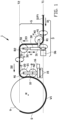
- Figure 1 show a strip-winding station 100 comprising a strip-winding drum 9 and a strip applicator 1 according to a first exemplary embodiment of the invention for applying a strip S to the strip-winding drum 9.
- the strip S is wound over a plurality of windings to form a tire component (not shown) for a green or unvulcanized tire.
- the strip S may be arranged in one or more layers, each layer comprising several side-by-side windings.
- the strip S as shown in figures 1-4 is schematically represented as thick line with no specific cross-sectional shape, width or height.
- the strip S may have a thin, flat and/or rectangular cross section, i.e. having a strip width that is greater than the strip height.
- the strip S has longitudinal sides or edges in its width direction and a top and bottom surface facing away from each other in the height direction. It will be understood that the strip S is guided through the strip applicator 1 with its top or bottom surface facing the guide surfaces or circumferential surfaces of the respective members and, more in particular, in an orientation with the aforementioned top or bottom surface of the strip extending parallel or substantially parallel to said guide surfaces or circumferential surfaces, described in more detail hereafter.
- twists and/or torsions in the strip S are schematically represented to occur within a relatively short length of the strip S. It will however be understood that such a twist or torsion can be more gradual and may extend over a longer length, i.e. over a considerable part or the entire length of the strip S between two consecutive members of the strip applicator 1.
- the strip S travels along a supply path P defined by the strip applicator 1 and is ultimately wound on the circumferential drum surface of the strip winding drum 9, which is only schematically show in dashed lines in figures 2-4 .
- the strip-winding drum 9 has a circumferential drum surface for receiving the strip S from the strip applicator 1.
- the strip-winding drum 9 is rotatable about a drum axis M, concentric to the circumferential drum surface.
- the strip-winding station 100 is configured for providing a relative movement between the strip-winding drum 9 and the strip applicator 1 to allow for the strip S to be applied across the circumferential drum surface in an axial direction A parallel to the drum axis M.
- the strip-winding drum 9 is movable in the axial direction A parallel to the drum axis M.
- the strip applicator 1 comprises an applicator member 2 for applying the strip to the strip-winding drum 9 at an application position A1 in the axial direction A.
- the applicator member 2 is an applicator roller comprising a roller body 20.
- the roller body 20 has or defines a circumferential surface 21 that is rotatable about an applicator axis N1.
- the applicator axis N1 is parallel or substantially parallel to the drum axis M and remains in a fixed orientation relative to said drum axis M.
- the strip applicator 1 further comprises a stitch member 8 for stitching the strip S after said strip S has been applied by applicator member 2 to the strip-winding drum 9.
- the stitch member 8 is rotatable about a stitch axis N2 parallel or substantially parallel to the applicator axis N1.
- the strip applicator 1 is provided with an applicator frame or holder 10 for holding the applicator member 2 relative to the strip-winding drum 9 and an applicator guide 15 for moving the applicator holder 10 in an offset direction X.
- the application position A1 moves or is offset together with the applicator member 2 in the offset direction X.
- the offset direction X is parallel or substantially parallel to the drum axis M and/or the axial direction A.
- the stitch member 8 is also held by the applicator holder 10.
- the applicator holder 10 acts as a common support for both the applicator member 2 and the stitch member 8.
- the applicator member 2 is moved linearly in the offset direction X, i.e.
- the strip applicator 1 comprises an applicator drive 16, i.e. a linear drive, for actively driving and/or controlling the movement of the applicator holder 10 in the offset direction X.
- an applicator drive 16 i.e. a linear drive
- the strip applicator 1 comprises a supply section 3 for receiving the strip S from an upstream station (not shown).
- Said upstream station may for example be an extruder that feeds the strip S directly into the supply section 3 of the strip applicator 1.
- the upstream station may comprise one or more conveyors, buffer members, storage members or the like, i.e. a dancer roller and/or a festooner, to buffer the strip S between the extruder and the strip applicator 1.
- the supply section 3 is arranged for receiving the strip S at a supply position A2 in the axial direction A.
- the supply position A2 is fixed or stationary in the axial direction A during strip-winding.
- the strip applicator 1 is arranged for receiving the strip S along a supply path extending in a supply direction D1 into the supply section 3.
- the supply direction D1 is transverse or perpendicular to the offset direction X, the drum axis M and/or the axial direction A.
- the supply direction D1 is horizontal or substantially horizontal.
- the supply section 3 is configured for supplying the strip S to the applicator member 2 along an output path extending in an output direction D2.
- the output direction D2 is transverse or perpendicular to the offset direction X, the drum axis M and/or the axial direction A.
- the output direction D2 is parallel or substantially parallel to the input direction D1.
- the input path and the output path are parallel or substantially parallel, yet spaced apart.
- the supply section 3 comprises an input member 4 and an output member 5 which together define a transition segment G within the supply path P of the strip S, extending in a transition direction D3 transverse or perpendicular to the input direction D1, the output direction D2 and/or the offset direction X.
- the input member 4 is located at or near, in-line or substantially in-line with the supply position A2 in the input direction D1 for receiving the strip S in said input direction D1.
- the input member 4 comprises a roller body 40 with a circumferential surface 41 that is rotatable about an input axis R1.
- the input member 4 is configured to remain in the fixed or stationary input position A1 during strip-winding.
- the output member 5 comprises a roller body 50 with a circumferential surface 51 that is rotatable about an output axis R2.
- the input axis R1 and the output axis R2 are parallel or substantially parallel to each other.
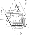
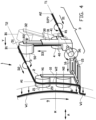
- the output member 5 is movable relative to the input member 4 from a start position B1, as shown in figure 2 , towards an offset position B2, as shown in figure 3 , in the offset direction X, or with (at least) a vector component V in the offset direction X.
- the output member 5 is arranged to follow the applicator member 2 as it moves in the offset direction X.
- the output member 5 or remains in-line or substantially in-line with the applicator member 2 in the output direction D2.
- the output member 5 and the applicator member 2 are moved synchronously in the offset direction X. This allows for the strip S to be outputted from the supply section 3 in the same output direction D2 regardless of the offset of the applicator member 2 in the offset direction X.
- the supply section 3 comprises a supply frame or holder 30 for holding the input member 4 and the output member 5 relative to each other and a supply drive 36 for rotating or tilting the supply holder 30 about a first twist axis T1.
- the first twist axis T1 is parallel or substantially parallel to the input direction D1 and/or perpendicular to the offset direction X.
- the transition segment G extends in a start orientation transverse to the output direction D2 and the offset direction X when the output member 5 is in the start position B1 and is tilted into an offset orientation oblique to the start orientation when the output member 5 is in the offset position B2.
- the first twist axis T1 is tangent to the circumferential surface 41 of the roller body 40 of the input member 4 and/or coincides or substantially coincides with the input path of the strip S.
- the tilting of the transition segment G about the first twist axis T1 mainly, predominantly or exclusively subjects the strip S to torsion about the first twist axis T1, along the input path, i.e. about the longitudinal axis of the strip S. In this way, bending, stretching or compression of the strip S at one of its longitudinal sides can be prevented.
- the supply holder 30 is configured for progressively moving the input member 4 and the output member 5 apart in an extension direction E parallel to the transition direction D3 and/or perpendicular to the first twist axis T1, thereby introducing a radial component to the movement of the output member 5 relative to said first twist axis T1.
- the output member 5 can thus remain at the same level as the applicator member 2 despite the tilt about the first twist axis T1.
- the supply holder 30 comprises a first holder part 31 holding the input member 4 and a second holder part 32 holding the output member 5.
- the second holder part 32 is movable, preferably telescopically, with respect to the first holder part 31 in an extension direction E to move the input member 4 and the output member 5 away from each other.
- the extension may be actively controlled, i.e. pneumatically.
- another mechanism may be used to obtain the extension of the supply holder 30 in the extension direction E, i.e. a linear drive, a linkage or the like.
- the output member 5 remains in-line with the applicator member 2 but is effectively rotated or tilted relative to said applicator member 2 about a second twist axis T2 tangent to the circumferential surface 51 of the output member 5 and the circumferential surface 21 of the applicator member 2.
- Said second twist axis T2 coincides or substantially coincides with the output path and/or is parallel or substantially parallel to the output direction D2. Again, this allows for the part of the strip S extending in said output path to be subjected mainly, predominantly or exclusively to torsion.
- the torsion in the strip S between the output member 5 and the applicator member 2 is opposite to the torsion upstream of the input member 4 so that the torsions substantially cancel each other out and the strip S is essentially in the same orientation upstream and downstream of the supply section 3.
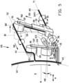
- Figure 5 shows an alternative strip applicator 101 according to a second exemplary embodiment of the invention that differs from the aforementioned strip applicator 1 in that the applicator member 2 can be rotated or tilted about a steering axis K transverse or perpendicular to the applicator axis N1, the drum axis M and/or the offset direction X.
- the applicator member 2 can be tilted between a neutral orientation, in which the applicator axis N1 extends parallel to the drum axis M, as shown in dashed lines, and a steering orientation in which the applicator axis N1 extends at a steering angle H oblique to the drum axis M, as shown in solid lines.
- the applicator holder 110 is divided into a first holder part 111 and a second holder part 112 that is rotatable relative to the first holder part 111 about the steering axis K.
- the alternative strip applicator 101 further comprises a steering drive 113 for driving the rotation of the second holder part 112 about the steering axis K.
- the steering axis K intersects with the stitcher axis N2.
- the steering axis K may be located closer to or at the applicator axis N1.
- the steering angle H may be set prior to winding or may be varied during winding.
- the steering angle H can be used to steer the strip in into and out of the transition area between the windings or during the application of the windings themselves to exert a sideways force onto the strip S.
- Figure 6 shows a further alternative strip applicator 201 according to a third exemplary embodiment of the invention, that differs from the aforementioned strip applicators 1, 101 in that applicator member 2 and the output member 5 are mechanically coupled and/or interconnected so as to move synchronously in the offset direction X.
- the supply section 203 comprises a supply holder 230 that is mechanically interconnected with the applicator holder 210 by a connecting frame or a connecting member 211. Said connecting member 211 forces the output member 5 to follow the position of the applicator member 2 in the offset direction X.
- the supply holder 230 is hingably coupled to the connecting member 211 such that the supply holder 230 can rotate relative to the connecting member 211 about the second twist axis T2, i.e. in line or coinciding with the longitudinal axis of the strip S in the output direction D2.
- the supply holder 230 ensures that the input member 4 and the output member 5 assume the same tilted orientation as a result of the displacement of the applicator member 2 in the offset direction X.
- the supply holder 230 can be telescopically extended as described before. However, the telescopic action of the supply holder 230 does not need to be driven actively, as the relative position between the output member 5 (coupled via the connecting member 211 to the applicator member 2) and the input member 4 can cause the supply holder 230 to follow and/or extent automatically or passively.
- Figures 7 and 8 show a further alternative strip applicator 301 according to a fourth exemplary embodiment of the invention, that differs from the aforementioned strip applicators 1, 101, 201 in that its supply section 303 is designed to increase the length of the transition segment G, so that the same offset in the offset direction X can be created with a relatively small angular displacement of said transition segment G.
- the strip S is twisted within the supply section 303, instead of upstream and downstream of said supply section 303.
- the supply section 303 comprises a first detour or diversion member 306 for receiving the strip S from the input member 304 and a second detour or diversion member 307 for feeding the strip S towards the output member 305.
- the first diversion member 306 is located at a side of the input member 304 facing away from the output member 305.
- the second diversion member 307 is located at a side of the output member 305 facing away from the input member 304.
- the transition segment G is defined between the first diversion member 306 and the second diversion member 307 and is therefore independent of the relatively positioning and/or distance between the input member 304 and the output member 305.
- the input member 304 comprises a roller body 340 with a circumferential surface 341 that is rotatable about an input axis R1.
- the input axis R1 is parallel or substantially parallel to the drum axis M, the axial direction A and/or the offset direction X.
- the output member 305 comprises a roller body 350 with a circumferential surface 351 that is rotatable about an output axis R2.
- the output axis R2 is parallel or substantially parallel to the input axis R1.
- the first diversion member 306 comprises a roller body 360 with a circumferential surface 361 that is rotatable about a first diversion axis R3 transverse or perpendicular to the input axis R1 and/or the transition direction D3.
- the second diversion member 307 comprises a roller body 370 with a circumferential surface 371 that is rotatable about a second diversion axis R4 transverse or perpendicular to the output axis R2.
- the second diversion axis R4 is parallel or substantially parallel to the first diversion axis R3.
- the strip S can thus be twisted twice within the supply section 303, once between the input member 304 and the first diversion member 306 and again between the second diversion member 307 and the output member 305.
- the twists are in opposite directions, so that the torsions in the strip S can cancel each other out.
- the strip S can be positioned optimally for entering into and exiting from the transition segment G without any significant stretching at the longitudinal sides of the strip S.
- the further alternative strip applicator 301 comprises a supply holder 330 that holds both the input member 304 and the first diversion member 306, and that is linearly movable over a supply guide 335 in the offset direction X.
- the applicator holder 310 and the supply holder 330 may be integrally interconnected or mechanically interconnected, i.e. by a connecting frame or a connecting member 311, to synchronize the movements in the offset direction X.
- the further alternative strip applicator 301 may be provided with a supply drive (not shown) for actively driving or controlling the linear movement of the supply holder 330 in said offset direction X in a synchronized manner with the applicator member 2.
- the transition segment G is rotated or tilted about the first diversion axis R3 with at least a vector component V in the offset direction X.
- the length of the transition segment G may increase slightly, but stretching is kept to a minimum because of the relatively large radius of the transition segment G relative to the first diversion axis R3 and the relatively small tilt angle.
- the strip S is first received into the strip applicator 1, 101, 201, 301 at the supply position A, and is subsequently guided through the supply section 3, 303 before it is ultimately supplied from the supply section 3, 303 to the applicator member 2 and applied to the strip-winding drum 9, optionally with the use of the stitcher member 8.
- the strip S is wound around the strip-winding drum 9 over two or more windings W1, W2.
- the applicator member 2 is quickly moved in the offset direction X to offset the application position A1 relative to the supply position A2.
- the strip S travels through a small transition area from the first winding W1 to the second winding W2, as shown in figures 3 and 8 , before continuing in the second winding W2, as shown in figure 4 .
- the output member 5, 305 is moved simultaneously with the applicator member 2 relative to the input member 4, 304 from the start position B1, as shown in figures 2 and 7 , towards the offset position B2, as shown in figures 3 and 8 .
- the part of the strip S between the output member 5, 305 and the applicator member 2 can thus be kept in-line or substantially in-line with each other, while the strip S is mainly subjected to torsion instead of stretch or compression.
- the strip-winding drum 9 can play catch-up by slowly moving in the offset direction X, while the applicator member 2 and the output member 5, 305 are returned at the same speed in a return direction Y opposite to the offset direction X. After returning to their initial positions, the strip applicator 1, 101, 201, 301 is ready for another quick offset in the offset direction X. If timed correctly, the strip-winding drum 9 can be moved at a constant slow speed, i.e. without interruption, while the strip applicator 1, 101, 201, 301 alternates between quick transitions and slow returns.
- Figures 9A and 9B show different options for controlling the behavior of the applicator member 2 relative to the strip-winding drum 9 to obtain transitions between windings W1, W2.
- Figure 9A shows a situation in which each transition of the strip S from one winding W1 to the next winding W2 is constant.
- the applicator member 2 is moved in the offset direction X at with an offset speed in a constant ratio to the rotation speed of the strip-winding drum 9.
- the shape, pitch, orientation and/or length of the strip S in the transition area between each pair winding W1, W2 is constant.
- each transition starts and ends at the same angular position in the circumferential direction.
- This strategy leaves relatively large gaps F1 in the outer windings W1, W2.
- Figure 9B shows a situation in which the ratio between the offset speed of the applicator member 2 and the rotation speed of the strip-winding drum 9 is varied between subsequent pairs of windings W1, W2 to obtain a variable, overall transition area Z2.
- the offset speed of the applicator member 2 in the offset direction X may be increased or decreased while the rotation speed of the strip-winding drum 9 remains constant. Consequently, the transition area Z2 formed by said variable ratio is not constant.
- the offset speed of the applicator member 2 is relatively high compared to the rotation speed of the strip-winding drum 9 for the outer windings in the axial direction A and is decreased towards more central windings W1, W2, to obtain a relatively short transition area, as indicated with dimensional arrows L1, L3, at the outer windings and a relatively long transition area, as indicated with dimensional arrow L2, at the central windings W1, W2.
- subsequent transitions can be shifted slightly with respect to each other in the circumferential direction such that the overall transition area Z2 extends obliquely or helically along the circumference of the strip-winding drum 9. This allows for the transitions to be nested closer together. As a result, the angle of the transition areas at the outer windings W1, W2 can be much sharper and the resulting gaps F2 at said outer windings W1, W2 much smaller.
- the transition segment G is not necessarily linear.
- a different type of applicator member, input member, output member or diversion member may be selected, i.e. from the group comprising brush rollers, crowned rollers, conveyors, belt conveyors, or the like.
Landscapes
- Engineering & Computer Science (AREA)
- Mechanical Engineering (AREA)
- Tyre Moulding (AREA)
- Replacement Of Web Rolls (AREA)
- Winding, Rewinding, Material Storage Devices (AREA)
- Winding Of Webs (AREA)
Claims (24)
- Applicateur de bande pour appliquer une bande sur un tambour d'enroulement de bande afin de former un composant de pneu, dans lequel l'applicateur de bande (1) comprend un élément d'applicateur (2) pour appliquer la bande sur le tambour d'enroulement de bande dans une position d'application et une section d'alimentation pour recevoir la bande dans une direction d'entrée dans une position d'alimentation et pour fournir la bande à l'élément d'applicateur dans une direction de sortie, dans lequel l'élément d'applicateur est mobile dans une direction de décalage transversale à la direction de sortie pour décaler la position d'application par rapport à la position d'alimentation, dans lequel la section d'alimentation comprend un élément d'entrée (4) dans la position d'alimentation pour recevoir la bande dans la direction d'entrée et un élément de sortie (5) pour transmettre la bande à l'élément d'applicateur dans la direction de sortie, dans lequel l'élément de sortie (5) est mobile par rapport à l'élément d'entrée (4) d'une position de départ vers une position de décalage avec au moins un composant de vecteur dans la direction de décalage, dans lequel la section d'alimentation définit une trajectoire d'alimentation pour la bande,
caractérisé en ce que :
la trajectoire d'alimentation, entre l'élément d'entrée (4) et l'élément de sortie (5), comprend un segment de transition (G) qui s'étend dans une orientation de départ transversale à la direction de sortie et la direction de décalage lorsque l'élément de sortie est dans la position de départ (B1) et qui est incliné dans une orientation de décalage oblique par rapport à l'orientation de départ lorsque l'élément de sortie est dans la position de décalage (B2), dans lequel le segment de transition (G) est inclinable autour d'un premier axe de torsion parallèle à la direction d'entrée, dans lequel l'élément d'entrée (4) et l'élément de sortie (5) sont inclinables dans leur ensemble autour du premier axe de torsion. - Applicateur de bande selon la revendication 1, dans lequel l'élément de sortie est agencé pour rester aligné ou sensiblement aligné avec l'élément d'applicateur dans la direction de sortie lorsque l'élément de sortie est déplacé de la position de départ vers la position de décalage, et/ou dans lequel l'élément de sortie et l'élément d'applicateur sont mobiles, de manière synchrone, dans la direction de décalage.
- Applicateur de bande selon la revendication 1 ou 2, dans lequel l'applicateur de bande comprend un support d'applicateur pour maintenir l'élément d'applicateur, dans lequel la section d'alimentation comprend un support d'alimentation pour maintenir l'élément de sortie, dans lequel le support d'applicateur et le support d'alimentation sont mécaniquement interconnectés pour synchroniser les mouvements de l'élément d'applicateur et de l'élément de sortie dans la direction de décalage.
- Applicateur de bande selon l'une quelconque des revendications précédentes, dans lequel le segment de transition s'étend dans une direction de transition transversale ou perpendiculaire à la direction de décalage et à la direction de sortie dans l'orientation de départ.
- Applicateur de bande selon la revendication 1, dans lequel l'élément d'entrée comprend un corps de rouleau avec une surface circonférentielle, dans lequel le premier axe de torsion est tangent par rapport à la surface circonférentielle du corps de rouleau de l'élément d'entrée,
encore de préférence, dans lequel l'élément d'entrée est agencé pour recevoir la bande dans la direction d'entrée le long d'une trajectoire d'entrée, dans lequel le premier axe de torsion coïncide ou coïncide sensiblement avec la trajectoire d'entrée. - Applicateur de bande selon la revendication 4, dans lequel l'élément de sortie comprend un corps de rouleau avec une surface circonférentielle et dans lequel l'élément d'applicateur comprend un corps de rouleau avec une surface circonférentielle, dans lequel l'élément de sortie peut s'incliner par rapport à l'élément d'applicateur autour d'un second axe de torsion tangent par rapport à la surface circonférentielle de l'élément de sortie et la surface circonférentielle de l'élément d'applicateur.
- Applicateur de bande selon la revendication 1, dans lequel la section d'alimentation comprend un support d'alimentation pour maintenir l'élément d'entrée et l'élément de sortie par rapport au premier axe de torsion, dans lequel le support d'alimentation, l'élément d'entrée et l'élément de sortie peuvent s'incliner dans leur ensemble autour du premier axe de torsion,encore de préférence, dans lequel le support d'alimentation comprend une première partie de support supportant l'élément d'entrée et une seconde partie de support supportant l'élément de sortie, dans lequel la seconde partie de support est mobile par rapport à la première partie de support dans une direction d'extension, en particulier dans une direction d'extension perpendiculaire ou transversale par rapport au premier axe de torsion, afin de déplacer l'élément d'entrée et l'élément de sortie à l'opposé l'un de l'autre,de manière préférée entre toutes, dans lequel la seconde partie de support est mobile, par voie télescopique, par rapport à la première partie de support dans ladite direction d'extension.
- Applicateur de bande selon la revendication 5, dans lequel la section d'alimentation comprend un premier élément de dérivation pour recevoir la bande de l'élément d'entrée et un second élément de dérivation pour alimenter la bande vers l'élément de sortie, dans lequel le segment de transition est défini entre le premier élément de dérivation et le second élément de dérivation,
de préférence, dans lequel le premier élément de dérivation est positionné sur un côté de l'élément d'entrée orienté à l'opposé de l'élément de sortie et/ou dans lequel le second élément de dérivation est positionné sur un côté de l'élément de sortie orienté à l'opposé de l'élément d'entrée. - Applicateur de bande selon la revendication 8, dans lequel l'élément d'entrée comprend un corps de rouleau avec une surface circonférentielle qui peut tourner autour d'un axe d'entrée et dans lequel le premier élément de dérivation comprend un corps de rouleau avec une surface circonférentielle qui peut tourner autour d'un premier axe de dérivation transversal ou perpendiculaire à l'axe d'entrée,de préférence dans lequel l'élément de sortie comprend un corps de rouleau avec une surface circonférentielle qui peut tourner autour d'un axe de sortie et dans lequel le second élément de dérivation comprend un corps de rouleau avec une surface circonférentielle qui peut tourner autour d'un second axe de dérivation transversal ou perpendiculaire à l'axe de sortie,encore de préférence, dans lequel le premier axe de dérivation et le second axe de dérivation sont parallèles ou sensiblement parallèles entre eux.
- Applicateur de bande selon la revendication 8 ou 9, dans lequel le premier élément de dérivation comprend un corps de rouleau avec une surface circonférentielle qui peut tourner autour d'un premier axe de dérivation, dans lequel le segment de transition peut s'incliner autour du premier axe de dérivation.
- Applicateur de bande selon l'une quelconque des revendications 8 à 10, dans lequel le second élément de dérivation et l'élément de sortie sont mobiles de manière linéaire dans la direction de décalage.
- Applicateur de bande selon l'une quelconque des revendications précédentes, dans lequel l'élément d'entrée comprend un corps de rouleau avec une surface circonférentielle qui peut tourner autour d'un axe d'entrée et dans lequel l'élément de sortie comprend un corps de rouleau avec une surface circonférentielle qui peut tourner autour d'un axe de sortie parallèle à l'axe d'entrée.
- Applicateur de bande selon l'une quelconque des revendications précédentes, dans lequel la direction d'entrée et la direction de sortie sont parallèles ou sensiblement parallèles.
- Applicateur de bande selon l'une quelconque des revendications précédentes, dans lequel l'élément d'applicateur est mobile de manière linéaire dans la direction de décalage.
- Applicateur de bande selon l'une quelconque des revendications précédentes, dans lequel l'élément d'applicateur comprend un corps de rouleau avec une surface circonférentielle qui peut tourner autour d'un axe d'applicateur, dans lequel l'orientation de l'axe d'applicateur reste fixe pendant le mouvement de l'élément d'applicateur dans la direction de décalage.
- Station d'enroulement de bande comprenant l'applicateur de bande selon l'une quelconque des revendications précédentes et un tambour d'enroulement de bande,
de préférence, dans laquelle le tambour d'enroulement de bande peut tourner autour d'un axe de tambour, dans lequel la direction de décalage est parallèle ou sensiblement parallèle à l'axe de tambour. - Station d'enroulement de bande selon la revendication 16, dans laquelle l'élément d'applicateur comprend un corps de rouleau avec une surface circonférentielle qui peut tourner autour d'un axe d'applicateur, dans lequel l'élément d'applicateur peut tourner autour d'un axe de direction transversal par rapport à l'axe d'applicateur entre une orientation neutre dans laquelle l'axe d'applicateur s'étend parallèlement à l'axe de tambour et une orientation de direction dans laquelle l'axe d'applicateur s'étend à un angle de direction oblique par rapport à l'axe de tambour.
- Procédé pour appliquer une bande sur un tambour d'enroulement de bande en utilisant l'applicateur de bande selon l'une quelconque des revendications 1 à 15, dans lequel le procédé comprend les étapes suivantes :- recevoir la bande dans la direction d'entrée dans la section d'alimentation dans la position d'alimentation ;- alimenter la bande de la section d'alimentation à l'élément d'applicateur dans la direction de sortie ;- appliquer la bande sur le tambour d'enroulement de bande dans la position d'application en enroulant la bande autour du tambour d'enroulement de bande sur deux tours ou plus ;- déplacer l'élément d'applicateur dans la direction de décalage transversale à la direction de sortie pour décaler la position d'application par rapport à la position d'alimentation ; et- déplacer l'élément de sortie par rapport à l'élément d'entrée de la position de départ vers la position de décalage avec au moins un composant de vecteur dans la direction de décalage.
- Procédé selon la revendication 18, dans lequel l'élément de sortie reste aligné ou sensiblement aligné avec l'élément d'applicateur dans la direction de sortie lorsque l'élément de sortie est déplacé de la position de départ vers la position de décalage, et/ou dans lequel l'élément de sortie et l'élément d'applicateur se déplacent de manière synchrone dans la direction de décalage.
- Procédé selon la revendication 18 ou 19, dans lequel la bande est soumise à une torsion dans une position entre l'élément de sortie et l'élément d'applicateur suite au déplacement de l'élément de sortie dans la direction de décalage,
de préférence dans lequel la bande est soumise à une torsion opposée à la torsion entre l'élément de sortie et l'élément d'applicateur dans une position en amont de l'élément d'entrée par rapport à la direction d'entrée. - Procédé selon la revendication 18 ou 19, dans lequel la bande est soumise aux torsions opposées dans deux positions espacées entre l'élément d'entrée et l'élément de sortie.
- Procédé selon l'une quelconque des revendications 18 à 21, dans lequel l'élément d'applicateur comprend un corps de rouleau avec une surface circonférentielle qui peut tourner autour d'un axe d'applicateur, dans lequel le procédé comprend en outre l'étape pour faire tourner l'élément d'applicateur autour d'un axe de direction transversal par rapport à l'axe d'applicateur entre une orientation neutre dans laquelle l'axe d'applicateur s'étend parallèlement à l'axe de tambour et une orientation de direction dans laquelle l'axe d'applicateur s'étend à un angle de direction oblique par rapport à l'axe de tambour.
- Procédé selon l'une quelconque des revendications 18 à 22, dans lequel le procédé comprend en outre les étapes suivantes :- déplacer le tambour d'enroulement de bande dans la direction de décalage ; et- retourner simultanément l'élément d'applicateur et l'élément de sortie dans une direction de retour opposée à la direction de décalage.
- Procédé selon l'une quelconque des revendications 18 à 23, dans lequel l'élément d'applicateur est déplacé dans la direction de décalage à une vitesse de décalage dans un rapport sur une vitesse de rotation du tambour d'enroulement de bande autour de l'axe de tambour, dans lequel le procédé comprend en outre l'étape suivante :- modifier le rapport pour les paires successives d'enroulements de la bande.
Priority Applications (2)
| Application Number | Priority Date | Filing Date | Title |
|---|---|---|---|
| RS20250641A RS66955B1 (sr) | 2021-08-26 | 2022-08-26 | Aplikator trake, stanica za namotavanje trake i postupak nanošenja trake na bubanj za namotavanje trake |
| MA66149A MA66149B1 (fr) | 2021-08-26 | 2022-08-26 | Applicateur de bande, station d'enroulement de bande et procédé pour l'application d'une bande sur un tambour d'enroulement de bande |
Applications Claiming Priority (2)
| Application Number | Priority Date | Filing Date | Title |
|---|---|---|---|
| NL2029062A NL2029062B1 (en) | 2021-08-26 | 2021-08-26 | Strip applicator, strip-winding station and method for applying a strip to a strip-winding drum |
| PCT/NL2022/050488 WO2023027587A1 (fr) | 2021-08-26 | 2022-08-26 | Applicateur de bande, station d'enroulement de bande et procédé pour l'application d'une bande sur un tambour d'enroulement de bande |
Publications (3)
| Publication Number | Publication Date |
|---|---|
| EP4392242A1 EP4392242A1 (fr) | 2024-07-03 |
| EP4392242B1 true EP4392242B1 (fr) | 2025-04-30 |
| EP4392242C0 EP4392242C0 (fr) | 2025-04-30 |
Family
ID=78135061
Family Applications (1)
| Application Number | Title | Priority Date | Filing Date |
|---|---|---|---|
| EP22761296.7A Active EP4392242B1 (fr) | 2021-08-26 | 2022-08-26 | Applicateur de bande, station d'enroulement de bande et procédé pour l'application d'une bande sur un tambour d'enroulement de bande |
Country Status (15)
| Country | Link |
|---|---|
| US (1) | US12246504B2 (fr) |
| EP (1) | EP4392242B1 (fr) |
| JP (1) | JP7574326B2 (fr) |
| KR (1) | KR102844709B1 (fr) |
| CN (2) | CN115724258A (fr) |
| CA (1) | CA3227778A1 (fr) |
| ES (1) | ES3027832T3 (fr) |
| HU (1) | HUE072136T2 (fr) |
| MA (1) | MA66149B1 (fr) |
| MX (1) | MX2024002412A (fr) |
| NL (1) | NL2029062B1 (fr) |
| PL (1) | PL4392242T3 (fr) |
| RS (1) | RS66955B1 (fr) |
| TW (1) | TW202406728A (fr) |
| WO (1) | WO2023027587A1 (fr) |
Family Cites Families (17)
| Publication number | Priority date | Publication date | Assignee | Title |
|---|---|---|---|---|
| LU87565A1 (fr) * | 1988-07-28 | 1989-10-26 | Goodyear Tire & Rubber | Procede et appareil d'application de spires pour fabrication d'une bande de roulement |
| EP1647394B1 (fr) * | 2004-10-14 | 2008-01-30 | Sumitomo Rubber Industries Ltd. | Procédé et dispositif pour la fabrication d'un objet par enroulement d'une bandelette en caoutchouc sur un support |
| KR100635023B1 (ko) * | 2005-10-20 | 2006-10-16 | 한국타이어 주식회사 | 그린타이어의 벨트 보강용 스트립 공급장치 |
| JP4392400B2 (ja) * | 2005-11-09 | 2009-12-24 | 住友ゴム工業株式会社 | 空気入りタイヤ |
| FR2914581B1 (fr) * | 2007-04-05 | 2009-07-03 | Michelin Soc Tech | Dispositif, installation et procede pour l'application d'une bande de gomme sur une ebauche de pneumatique. |
| WO2009031435A1 (fr) * | 2007-09-05 | 2009-03-12 | Bridgestone Corporation | Procédé et appareil pour la fabrication d'un pneu non vulcanisé |
| JP5001798B2 (ja) | 2007-11-19 | 2012-08-15 | 東洋ゴム工業株式会社 | タイヤ及びタイヤの成型方法 |
| JP5423498B2 (ja) * | 2010-03-16 | 2014-02-19 | 横浜ゴム株式会社 | 未加硫ゴム材料の供給システム |
| JP5832188B2 (ja) * | 2011-07-22 | 2015-12-16 | 住友ゴム工業株式会社 | ゴムストリップの貼り付け方法 |
| NL2009946C2 (en) * | 2012-12-10 | 2014-06-11 | Vmi Holland Bv | Tyre building machine for forming a bead-apex assembly. |
| JP5767623B2 (ja) * | 2012-12-27 | 2015-08-19 | 住友ゴム工業株式会社 | ゴムストリップの貼付装置 |
| US10307980B2 (en) * | 2013-02-20 | 2019-06-04 | The Goodyear Tire & Rubber Company | Tire building applicator members and systems |
| JP5797730B2 (ja) * | 2013-12-24 | 2015-10-21 | 株式会社ブリヂストン | 帯状部材の巻付け装置 |
| JP5945290B2 (ja) | 2014-02-24 | 2016-07-05 | 住友ゴム工業株式会社 | タイヤ部材形成装置 |
| JP2020093411A (ja) * | 2018-12-10 | 2020-06-18 | 住友ゴム工業株式会社 | タイヤ部材の製造方法 |
| US11964444B2 (en) * | 2019-06-26 | 2024-04-23 | Pirelli Tyre S.P.A. | Method for building tyres |
| CN110422666B (zh) * | 2019-07-26 | 2024-03-26 | 河北万达轮胎有限公司 | 带束层胶片隔离膜卷取装置 |
-
2021
- 2021-08-26 NL NL2029062A patent/NL2029062B1/en active
-
2022
- 2022-07-29 TW TW111128603A patent/TW202406728A/zh unknown
- 2022-08-26 RS RS20250641A patent/RS66955B1/sr unknown
- 2022-08-26 CN CN202211032612.XA patent/CN115724258A/zh active Pending
- 2022-08-26 CA CA3227778A patent/CA3227778A1/fr active Pending
- 2022-08-26 MA MA66149A patent/MA66149B1/fr unknown
- 2022-08-26 CN CN202222267945.2U patent/CN218619408U/zh active Active
- 2022-08-26 MX MX2024002412A patent/MX2024002412A/es unknown
- 2022-08-26 WO PCT/NL2022/050488 patent/WO2023027587A1/fr not_active Ceased
- 2022-08-26 PL PL22761296.7T patent/PL4392242T3/pl unknown
- 2022-08-26 HU HUE22761296A patent/HUE072136T2/hu unknown
- 2022-08-26 JP JP2022571739A patent/JP7574326B2/ja active Active
- 2022-08-26 EP EP22761296.7A patent/EP4392242B1/fr active Active
- 2022-08-26 ES ES22761296T patent/ES3027832T3/es active Active
- 2022-08-26 US US18/686,695 patent/US12246504B2/en active Active
- 2022-08-26 KR KR1020247009872A patent/KR102844709B1/ko active Active
Also Published As
| Publication number | Publication date |
|---|---|
| WO2023027587A1 (fr) | 2023-03-02 |
| JP7574326B2 (ja) | 2024-10-28 |
| HUE072136T2 (hu) | 2025-10-28 |
| US20240375365A1 (en) | 2024-11-14 |
| KR20240047464A (ko) | 2024-04-12 |
| MA66149B1 (fr) | 2025-05-30 |
| PL4392242T3 (pl) | 2025-09-01 |
| CA3227778A1 (fr) | 2023-03-02 |
| CN218619408U (zh) | 2023-03-14 |
| KR102844709B1 (ko) | 2025-08-08 |
| MX2024002412A (es) | 2024-04-05 |
| TW202406728A (zh) | 2024-02-16 |
| JP2023542579A (ja) | 2023-10-11 |
| US12246504B2 (en) | 2025-03-11 |
| EP4392242C0 (fr) | 2025-04-30 |
| CN115724258A (zh) | 2023-03-03 |
| NL2029062B1 (en) | 2023-03-15 |
| EP4392242A1 (fr) | 2024-07-03 |
| RS66955B1 (sr) | 2025-07-31 |
| ES3027832T3 (en) | 2025-06-17 |
Similar Documents
| Publication | Publication Date | Title |
|---|---|---|
| JP3492817B2 (ja) | ウェブの搬送装置および方法 | |
| US20230302709A1 (en) | Cooling apparatus and method for cooling a continuous strip | |
| CN101062737A (zh) | 用于将薄片材料绕到卷轴上的卷绕机及其相应的卷绕方法 | |
| CN113370563B (zh) | 用于运输轮胎部件的运输装置、施加器以及方法 | |
| US5328533A (en) | Bead apex applying method and device | |
| EP3177456B1 (fr) | Appareil pour détendre un bourrage pour talon de pneu et système de manipulation du bourrage comprenant ledit appareil | |
| US7665290B2 (en) | Twister, method for producing twisted wire, ply, and pneumatic tire | |
| US6461459B1 (en) | Method and apparatus for forming tire reinforcing layer | |
| US12246504B2 (en) | Strip applicator, strip-winding station and method for applying a strip to a strip-winding drum | |
| JPH01165429A (ja) | 板紙シート等の折曲げ装置 | |
| KR19990063634A (ko) | 다중와이어(wire = 철사) 스풀(spool)을 다중 와이어로 동시에 감으며/또는 이렇게 감겨진 다중스풀(spool)로부터 그의 다음 합연기를 위하여 와이어를 동시에 풀어주기 위한 방법 및 장치 | |
| US5048264A (en) | Process and apparatus for the temporary storage of multi-sheeted, folded printing products, such as newspapers, periodicals and parts thereof | |
| CA3082343C (fr) | Appareil de refroidissement et procede de refroidissement d'une bande continue | |
| JPH0512447U (ja) | 板状体折曲げ装置 | |
| KR19990072085A (ko) | 연속적으로들어오는실권취기계 | |
| JPH10337774A (ja) | フィルムの横延伸機とそのテンタークリップ走行案内装置 | |
| JPS62250624A (ja) | 環状鉄心コイル巻き付け装置 | |
| JPS58152760A (ja) | 糸捲取機のトラバ−ス装置 |
Legal Events
| Date | Code | Title | Description |
|---|---|---|---|
| STAA | Information on the status of an ep patent application or granted ep patent |
Free format text: STATUS: UNKNOWN |
|
| STAA | Information on the status of an ep patent application or granted ep patent |
Free format text: STATUS: THE INTERNATIONAL PUBLICATION HAS BEEN MADE |
|
| PUAI | Public reference made under article 153(3) epc to a published international application that has entered the european phase |
Free format text: ORIGINAL CODE: 0009012 |
|
| STAA | Information on the status of an ep patent application or granted ep patent |
Free format text: STATUS: REQUEST FOR EXAMINATION WAS MADE |
|
| 17P | Request for examination filed |
Effective date: 20240125 |
|
| AK | Designated contracting states |
Kind code of ref document: A1 Designated state(s): AL AT BE BG CH CY CZ DE DK EE ES FI FR GB GR HR HU IE IS IT LI LT LU LV MC MK MT NL NO PL PT RO RS SE SI SK SM TR |
|
| DAX | Request for extension of the european patent (deleted) | ||
| RAV | Requested validation state of the european patent: fee paid |
Extension state: MA Effective date: 20240125 |
|
| GRAP | Despatch of communication of intention to grant a patent |
Free format text: ORIGINAL CODE: EPIDOSNIGR1 |
|
| STAA | Information on the status of an ep patent application or granted ep patent |
Free format text: STATUS: GRANT OF PATENT IS INTENDED |
|
| INTG | Intention to grant announced |
Effective date: 20250213 |
|
| GRAS | Grant fee paid |
Free format text: ORIGINAL CODE: EPIDOSNIGR3 |
|
| GRAA | (expected) grant |
Free format text: ORIGINAL CODE: 0009210 |
|
| STAA | Information on the status of an ep patent application or granted ep patent |
Free format text: STATUS: THE PATENT HAS BEEN GRANTED |
|
| AK | Designated contracting states |
Kind code of ref document: B1 Designated state(s): AL AT BE BG CH CY CZ DE DK EE ES FI FR GB GR HR HU IE IS IT LI LT LU LV MC MK MT NL NO PL PT RO RS SE SI SK SM TR |
|
| REG | Reference to a national code |
Ref country code: CH Ref legal event code: EP Ref country code: GB Ref legal event code: FG4D |
|
| REG | Reference to a national code |
Ref country code: IE Ref legal event code: FG4D |
|
| REG | Reference to a national code |
Ref country code: MA Ref legal event code: VAGR Ref document number: 66149 Country of ref document: MA Kind code of ref document: B1 |
|
| U01 | Request for unitary effect filed |
Effective date: 20250502 |
|
| U07 | Unitary effect registered |
Designated state(s): AT BE BG DE DK EE FI FR IT LT LU LV MT NL PT RO SE SI Effective date: 20250509 |
|
| REG | Reference to a national code |
Ref country code: ES Ref legal event code: FG2A Ref document number: 3027832 Country of ref document: ES Kind code of ref document: T3 Effective date: 20250617 |
|
| PGFP | Annual fee paid to national office [announced via postgrant information from national office to epo] |
Ref country code: HU Payment date: 20250827 Year of fee payment: 4 |
|
| REG | Reference to a national code |
Ref country code: SK Ref legal event code: T3 Ref document number: E 46796 Country of ref document: SK |
|
| U20 | Renewal fee for the european patent with unitary effect paid |
Year of fee payment: 4 Effective date: 20250827 |
|
| PGFP | Annual fee paid to national office [announced via postgrant information from national office to epo] |
Ref country code: ES Payment date: 20250926 Year of fee payment: 4 |
|
| PG25 | Lapsed in a contracting state [announced via postgrant information from national office to epo] |
Ref country code: NO Free format text: LAPSE BECAUSE OF FAILURE TO SUBMIT A TRANSLATION OF THE DESCRIPTION OR TO PAY THE FEE WITHIN THE PRESCRIBED TIME-LIMIT Effective date: 20250730 Ref country code: GR Free format text: LAPSE BECAUSE OF FAILURE TO SUBMIT A TRANSLATION OF THE DESCRIPTION OR TO PAY THE FEE WITHIN THE PRESCRIBED TIME-LIMIT Effective date: 20250731 |
|
| PGFP | Annual fee paid to national office [announced via postgrant information from national office to epo] |
Ref country code: TR Payment date: 20250819 Year of fee payment: 4 Ref country code: PL Payment date: 20250818 Year of fee payment: 4 |
|
| PG25 | Lapsed in a contracting state [announced via postgrant information from national office to epo] |
Ref country code: HR Free format text: LAPSE BECAUSE OF FAILURE TO SUBMIT A TRANSLATION OF THE DESCRIPTION OR TO PAY THE FEE WITHIN THE PRESCRIBED TIME-LIMIT Effective date: 20250430 |
|
| PGFP | Annual fee paid to national office [announced via postgrant information from national office to epo] |
Ref country code: CZ Payment date: 20250818 Year of fee payment: 4 Ref country code: RS Payment date: 20250815 Year of fee payment: 4 |
|
| PGFP | Annual fee paid to national office [announced via postgrant information from national office to epo] |
Ref country code: SK Payment date: 20250818 Year of fee payment: 4 |
|
| PG25 | Lapsed in a contracting state [announced via postgrant information from national office to epo] |
Ref country code: IS Free format text: LAPSE BECAUSE OF FAILURE TO SUBMIT A TRANSLATION OF THE DESCRIPTION OR TO PAY THE FEE WITHIN THE PRESCRIBED TIME-LIMIT Effective date: 20250830 |
|
| REG | Reference to a national code |
Ref country code: HU Ref legal event code: AG4A Ref document number: E072136 Country of ref document: HU |
|
| VSFP | Annual fee paid to validation state [announced via postgrant information from national office to epo] |
Ref country code: MA Payment date: 20250819 Year of fee payment: 4 |
|
| PG25 | Lapsed in a contracting state [announced via postgrant information from national office to epo] |
Ref country code: SM Free format text: LAPSE BECAUSE OF FAILURE TO SUBMIT A TRANSLATION OF THE DESCRIPTION OR TO PAY THE FEE WITHIN THE PRESCRIBED TIME-LIMIT Effective date: 20250430 |
|
| PLBE | No opposition filed within time limit |
Free format text: ORIGINAL CODE: 0009261 |
|
| STAA | Information on the status of an ep patent application or granted ep patent |
Free format text: STATUS: NO OPPOSITION FILED WITHIN TIME LIMIT |
|
| REG | Reference to a national code |
Ref country code: CH Ref legal event code: L10 Free format text: ST27 STATUS EVENT CODE: U-0-0-L10-L00 (AS PROVIDED BY THE NATIONAL OFFICE) Effective date: 20260311 |
|
| REG | Reference to a national code |
Ref country code: CH Ref legal event code: H13 Free format text: ST27 STATUS EVENT CODE: U-0-0-H10-H13 (AS PROVIDED BY THE NATIONAL OFFICE) Effective date: 20260324 |
|
| PG25 | Lapsed in a contracting state [announced via postgrant information from national office to epo] |
Ref country code: MC Free format text: LAPSE BECAUSE OF FAILURE TO SUBMIT A TRANSLATION OF THE DESCRIPTION OR TO PAY THE FEE WITHIN THE PRESCRIBED TIME-LIMIT Effective date: 20250430 |
|
| 26N | No opposition filed |
Effective date: 20260202 |
|
| PG25 | Lapsed in a contracting state [announced via postgrant information from national office to epo] |
Ref country code: CH Free format text: LAPSE BECAUSE OF NON-PAYMENT OF DUE FEES Effective date: 20250831 |