EP4411105A2 - Tête de forage et procédé pour la réalisation d'un forage vertical dans le sol - Google Patents
Tête de forage et procédé pour la réalisation d'un forage vertical dans le sol Download PDFInfo
- Publication number
- EP4411105A2 EP4411105A2 EP24165434.2A EP24165434A EP4411105A2 EP 4411105 A2 EP4411105 A2 EP 4411105A2 EP 24165434 A EP24165434 A EP 24165434A EP 4411105 A2 EP4411105 A2 EP 4411105A2
- Authority
- EP
- European Patent Office
- Prior art keywords
- opening
- drill head
- suction box
- soil
- loosened
- Prior art date
- Legal status (The legal status is an assumption and is not a legal conclusion. Google has not performed a legal analysis and makes no representation as to the accuracy of the status listed.)
- Pending
Links
Images





Classifications
-
- E—FIXED CONSTRUCTIONS
- E21—EARTH OR ROCK DRILLING; MINING
- E21B—EARTH OR ROCK DRILLING; OBTAINING OIL, GAS, WATER, SOLUBLE OR MELTABLE MATERIALS OR A SLURRY OF MINERALS FROM WELLS
- E21B10/00—Drill bits
- E21B10/42—Rotary drag type drill bits with teeth, blades or like cutting elements, e.g. fork-type bits, fish tail bits
-
- E—FIXED CONSTRUCTIONS
- E21—EARTH OR ROCK DRILLING; MINING
- E21B—EARTH OR ROCK DRILLING; OBTAINING OIL, GAS, WATER, SOLUBLE OR MELTABLE MATERIALS OR A SLURRY OF MINERALS FROM WELLS
- E21B10/00—Drill bits
- E21B10/60—Drill bits characterised by conduits or nozzles for drilling fluids
- E21B10/602—Drill bits characterised by conduits or nozzles for drilling fluids the bit being a rotary drag type bit with blades
-
- E—FIXED CONSTRUCTIONS
- E21—EARTH OR ROCK DRILLING; MINING
- E21B—EARTH OR ROCK DRILLING; OBTAINING OIL, GAS, WATER, SOLUBLE OR MELTABLE MATERIALS OR A SLURRY OF MINERALS FROM WELLS
- E21B21/00—Methods or apparatus for flushing boreholes, e.g. by use of exhaust air from motor
- E21B21/12—Methods or apparatus for flushing boreholes, e.g. by use of exhaust air from motor using drilling pipes with plural fluid passages, e.g. closed circulation systems
-
- E—FIXED CONSTRUCTIONS
- E21—EARTH OR ROCK DRILLING; MINING
- E21D—SHAFTS; TUNNELS; GALLERIES; LARGE UNDERGROUND CHAMBERS
- E21D9/00—Tunnels or galleries, with or without linings; Methods or apparatus for making thereof; Layout of tunnels or galleries
- E21D9/10—Making by using boring or cutting machines
-
- E—FIXED CONSTRUCTIONS
- E21—EARTH OR ROCK DRILLING; MINING
- E21D—SHAFTS; TUNNELS; GALLERIES; LARGE UNDERGROUND CHAMBERS
- E21D9/00—Tunnels or galleries, with or without linings; Methods or apparatus for making thereof; Layout of tunnels or galleries
- E21D9/10—Making by using boring or cutting machines
- E21D9/1006—Making by using boring or cutting machines with rotary cutting tools
-
- E—FIXED CONSTRUCTIONS
- E21—EARTH OR ROCK DRILLING; MINING
- E21D—SHAFTS; TUNNELS; GALLERIES; LARGE UNDERGROUND CHAMBERS
- E21D9/00—Tunnels or galleries, with or without linings; Methods or apparatus for making thereof; Layout of tunnels or galleries
- E21D9/10—Making by using boring or cutting machines
- E21D9/11—Making by using boring or cutting machines with a rotary drilling-head cutting simultaneously the whole cross-section, i.e. full-face machines
-
- E—FIXED CONSTRUCTIONS
- E21—EARTH OR ROCK DRILLING; MINING
- E21D—SHAFTS; TUNNELS; GALLERIES; LARGE UNDERGROUND CHAMBERS
- E21D1/00—Sinking shafts
- E21D1/03—Sinking shafts mechanically, e.g. by loading shovels or loading buckets, scraping devices, conveying screws
- E21D1/06—Sinking shafts mechanically, e.g. by loading shovels or loading buckets, scraping devices, conveying screws with shaft-boring cutters
Definitions
- the invention relates to a drill head and a method for creating a substantially vertical bore in the ground, in particular for creating a shaft, with a body that can be connected to a rotary drive of a drilling device, with drilling tools arranged on the body for loosening the soil at a working face of the bore, with a removal device for transporting the loosened soil at the working face, which can be connected to a suction unit for sucking in a conveying medium via a conveyor line, wherein the removal device has an opening region arranged on the body with at least one opening in the region of the drilling tools at the working face.
- Such a drill head is made, for example, of US 4646853 A , EP2597249B1 , US 3384191 A , US 4195700 A and US 4200160 A known.
- US 4646853 A discloses a device and a method for sinking a shaft.
- a cutting wheel that can rotate about a vertical axis is provided for loosening the soil.
- a mechanical conveying system with buckets is provided for removing the loosened soil.
- EP2597249B1 shows a drilling device for drilling vertical boreholes in the ground with a drill head that rotates on a working face.
- a suction device is provided that has an opening that is located on the outside of the end of the drill head facing the working face and rotates with the drill head. Loosened soil is thereby removed from the borehole.
- US 3384191 A shows a drill head with roller bits, which also has a suction system for removing the loosened soil.
- a guide plate is provided that is arranged in the area of the suction opening and collects the loosened soil as the drill head rotates and feeds it to the opening. Behind the opening there is an inclined channel that opens into a centrally arranged discharge line.
- US 4195700 A also discloses a drill head with roller bits, which has a radial opening, at the inner end of which a discharge line is provided.
- the opening is designed as a slot, behind which a conical tube is provided, which widens towards the discharge line.
- US 4200160 A discloses a drill head with a suction system for removing the loosened soil.
- the suction system has a slot-shaped radial opening that opens into a cylindrical space. A channel emerges from this and leads into the sewage pipe.
- the object of the invention is to simplify the suction of the aforementioned drill heads and at the same time to improve their performance.
- the at least one opening of the opening region is connected to a suction box as a component of the removal device, which has a connection opening for a connection to the conveyor line at an end opposite the opening, in that at least one element is provided which exerts an acceleration on the loosened soil in the region of the suction box, by means of which the soil loosened by the drilling tools can be moved into the opening region and/or through the opening into the suction box, wherein the loosened soil in the opening region, preferably in the opening and/or in the suction box, is grasped by the conveyor medium and can be removed by the suction unit via the conveyor line.
- a further teaching of the invention provides that the at least one element is at least one nozzle which is directed into the opening region and which emits at least one jet of a transport medium for causing the acceleration.
- a further teaching of the invention provides that behind the opening there is at least one deflection area, preferably before entering the suction box, in which the flow direction of the loosened soil can be deflected. This makes it particularly easy to feed the material to be removed to the conveyor and then remove it.
- a further teaching of the invention provides that at least one tool for loosening the soil, preferably in the form of a toothed strip, and/or for picking up loosened soil is provided in the opening area. This allows rock/soil to be loosened/picked up at the face directly in the opening area. The material loosened/picked up in this way can be fed particularly well to the suction system.
- the at least one tool is movable to change the distance of the tool from the working face, preferably via at least one hydraulic cylinder, and/or that the at least one tool is pivotable relative to the opening region, preferably via at least one hydraulic cylinder.
- a further teaching of the invention provides that the distance of the opening area from the working face is adjustable. It is advantageous that the distance is adjusted by vertically moving the suction box and/or pivoting the suction box about a pivot point, with a drive, preferably a hydraulic cylinder or a spring mechanism, being provided for the movement or pivoting. This makes it possible to directly influence the amount of material sucked out in a simple manner.
- a further teaching of the invention provides that a cleaning tool, preferably at least one movable element and/or at least one nozzle for dispensing a medium, for example a gas (air) or a liquid (water, bentonite rinse), is provided in the opening area.
- a cleaning tool preferably at least one movable element and/or at least one nozzle for dispensing a medium, for example a gas (air) or a liquid (water, bentonite rinse) is provided in the opening area.
- a medium for example a gas (air) or a liquid (water, bentonite rinse
- a further teaching of the invention provides that at least one flushing nozzle is provided, with which soil loosened by at least one drilling tool can be transported to an area on the face over which the suction box passes with the drill head during drilling. This improves the transport of material to the suction box in a simple manner.
- a further teaching of the invention provides that the suction box is provided in the drill head so that it can be changed. This allows the drill head to be easily adapted to different geological conditions. Furthermore, it is also possible to reverse the direction of rotation.
- a further teaching of the invention provides that a classification element is provided in the opening area.
- This can be, for example, a grid, dividing plates that divide the opening area into several openings, or even several openings. This makes it easy to limit the grain size of the sucked-in material.
- a further teaching of the invention provides that the suction box is arranged essentially horizontally. This has a positive effect on the material transport in the suction box and the material intake.
- a further teaching of the invention provides that the opening area extends essentially radially outwards from the center. It is advantageous that the opening is elongated or slot-like. A further teaching of the invention provides that the clear cross section of the opening changes, preferably increases, along the opening area radially outwards. This makes it easy to influence the material intake, the location of the material intake and the intake quantity.
- connection opening of the suction box is offset from a central perpendicular of the opening area, preferably outwards.
- the suction box is constructed asymmetrically.
- the suction strength or the flow profile in the suction box or in the opening area can be easily influenced so that the amount of material sucked in can be influenced. For example, by moving it outwards, the flow in the radially outer area of the suction box can be increased in order to be able to better suck up the larger amount of material that accumulates there.
- connection opening of the suction box is arranged pivoted relative to the opening area relative to a perpendicular bisector of the opening area.
- the suction strength or the flow profile in the suction box or in the opening area can be influenced in a simple manner, so that the amount of material sucked in can be influenced. For example, by tilting the connection opening inwards, the flow in the radially outer area of the suction box can be increased in order to be able to better suck up the larger amount of material that accumulates there.
- a further teaching of the invention provides that the suction box has at least one nozzle in the interior. This makes it possible to improve the movement of the loosened soil/rock for capture by the conveying medium in a simple manner.
- a further teaching of the invention provides that the conveying medium and/or the transport medium is a liquid or gaseous medium, preferably water, a bentonite suspension or air.
- the conveying medium is air and the transport medium is air or a liquid, preferably water. This is used when the drill head is not/should not/cannot be flooded and thus liquid-based conveying is not possible. It has surprisingly been shown that the loosened soil/rock can be easily transported/activated by the jet emitted and can be advantageously fed into and removed from the conveying flow of air.
- a further teaching of the invention provides that the at least one element is at least one driven rotary element with at least one impact element arranged thereon, wherein the at least one impact element causes the acceleration of the loosened soil via a contact by means of a rotational movement.
- the impact element can be moved on an impact circle which is provided concentrically around the rotation element.
- a further teaching of the invention provides that the at least one impact element is movably arranged on the at least one rotation element, preferably via a joint.
- a further teaching of the invention provides that the at least one striking element is a hammer, a sword, a rope, a chain, a brush element, or a chisel.
- a further teaching of the invention provides that the rotation of the at least one rotation element is speed-adjustable.
- a further teaching of the invention provides that the at least one impact element causes a comminution of the loosened soil.
- a further teaching of the invention provides that the suction box is provided horizontally, inclined and/or vertically.
- a further teaching of the invention provides that the loosened soil is moved through the opening into the suction box by the introduced acceleration.
- a further teaching of the invention provides that the detection takes place in the suction box and/or in the opening area, preferably in front of the opening.
- a further teaching of the invention provides that the acceleration is carried out by emitting a jet of a transport medium from a nozzle which is directed into the opening area of the suction box as a component of the discharge device.
- a further teaching of the invention provides that the movement of the loosened soil is carried out by the transport medium.
- the acceleration is carried out by at least one driven rotary element with at least one impact element arranged thereon, wherein the at least one impact element causes the acceleration of the loosened soil via a contact by means of a rotational movement.
- a further teaching of the invention provides that the movement of the loosened soil is carried out by the impact element.
- the conveying medium and/or the transport medium is a liquid or gaseous medium, preferably water, a bentonite suspension or air
- Figure 1 shows a three-dimensional representation of a drill head 10 according to the invention in a first embodiment.
- the drill head 10 has a body 11 on which on its underside 13 Drilling tools 12 are arranged.
- the drill head 10 On its upper side 14, the drill head 10 has a connection (not shown) for a drive (not shown) of a drilling device (not shown).
- the drive (not shown) is provided, for example, directly in the drilling device, for example a shaft boring machine.
- Other variants of drives, drilling devices and arrangements, for example in a borehole/pile/casing, are also possible.
- the underside 13 has a ring section 15, which is here for example flat (other shapes are possible), on the underside 16 of which drilling tools 12 are provided.
- Arms extend outwards from the ring section, here for example 8 arms, 17, each of which has a flat flank 18.
- Broaching tools 19 and wear elements 40 can be provided on the flanks.
- the flanks 18 can also be designed to run all the way around.
- a recess 41 is provided, which has, for example, a flat surface 42 and flanks 43, on which drilling tools 12 are also provided.
- the drill head shape described here is also called a W-drill head.
- the drill profile is shown in the Figures 8 and 9
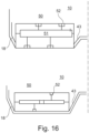
- the width of the flat ring section 15 as well as the angles of the inner and outer flanks 43, 18 and the size of the inner surface 42 are variable and depend on the mining conditions, as in Figure 16 is shown.
- the drilling tools 12 can be, for example, disk chisels 12a, paring chisels or paring knives 12b or roller chisels 12c or other alternatives.
- the drilling tools 12 are selected depending on the soil/rock to be loosened to create the borehole.
- Figure 1 On its upper side 14 is Figure 1 the connection 45 of the delivery line 31 is shown.
- the body 11 has a suction box 20 on its underside 13 of the W-drill head 10 on the ring section 15.
- FIG. 4 Alternative arrangements of the suction box 20 are shown in Figure 4
- the suction box 20 is located, for example, in the case of a conical or V-shaped drill head in the deepest part of the borehole (left in Figure 4 ) or extends and is provided radially in a flat drill head (right in Figure 4 ).
- a W-drill head is shown in the middle of Figure 4
- FIG.4 Also shown are designs possible in which the suction box 20 is inclined or vertical and, for example, its opening 23 is directed downwards towards the working face 100.
- the suction box 20 in a first embodiment has an opening region 22 on its front side 21, which has at least one opening 23.
- the opening 23 of the first embodiment of the suction box 20 has a classification element 24, which divides the opening 23 into opening sections 23a.
- the classification element 24 determines the grain size of the loosened soil/rock that can enter the interior 25 of the suction box 20.
- the interior 25 is formed by a cover 26 as the top and a base 27 as the bottom, which are designed to be flat in one embodiment. Other shapes of cover and base are also possible.
- the suction box 20 also has side walls 28, which here extend from the front 21 along the shape of the cover and base.
- the shape of the interior 25 of the suction box 20 is determined by the shape of the cover 26, the base 27 and the side walls 28. This can be a box-like structure. Alternatively, a funnel can be present if the width of the interior 25 is reduced, for example, by a curved shape of the side walls 28, whereby the flow speed of the mixture of dissolved soil/rock and carrier medium increases with decreasing width.
- An opening 29 is provided on the rear side of the interior space 25, at which a connection 30 for a conveying capacity 31 is provided, which is connected to a suction unit/pump (not shown) during drilling operation in order to carry out the removal of the loosened soil/rock or the mixture of conveying medium and loosened soil/rock.
- the height of the interior 25 of the suction box 20 can be varied, in particular increased, starting from the front 21 to the opening 29 at the rear of the suction box 20 in order to counteract blockages of the interior 25 by loosened soil/rock.
- suction box 20 which is shown symmetrically here, asymmetrically, for example by arranging the opening 29 laterally offset (not shown).
- This can be particularly useful, for example, in the case of a flat designed drill head, if the extension of the opening area 22 is longer, to arrange the opening 29 offset towards the outer circumference of the body 11 in order to specifically increase the flow velocity in the areas in which more soil/rock is loosened during the rotation of the drill head and enters the interior 25 of the suction box 20 through the opening 23.
- connection 30 of the conveying capacity 31 opens at an angle while falling into the interior space 25.
- the opening area 22 can have soil loosening tools and/or soil collection tools 33, for example scraper knives or scrapers, in the area of the opening 23, which extends along the front side 21.
- soil loosening tools and/or soil collection tools 33 for example scraper knives or scrapers, in the area of the opening 23, which extends along the front side 21.
- guide plates can also be provided on the underside 13 of the drill head 10 (not shown), which feed loosened material to the opening area 22.
- the feeding can be supported by nozzles such as rinsing nozzles 32.
- Fig.2 and Figure 3 show a section of the drill head 10 according to the invention with a suction box 20 with an opening 23 and nozzles 34 directed thereon for delivering a transport medium 80, preferably air or a liquid such as water or bentonite flushing.
- the transport medium 90 is sucked in through the conveyor line 31, which is connected to the suction box 20 via the opening 29 and the connection 30.
- Loosened soil 110 is accelerated by the transport medium jet 81 and transported through the opening 23. There, the loosened soil 110 is captured by the transport medium 90.
- Loosened soil 110, transport medium 90 and transport medium 80 mix to form a transport flow 120, which is then transported away via the conveyor line.
- the transport medium jet 81 causes the loosened soil 110 to be swirled up or released from the working face 100 in the opening region 22 due to the acceleration input, so that the swirled up loosened soil is already captured there by the conveying medium 90 and is conveyed away with the conveying medium as a conveying flow 120.
- Figure 5 shows an arm 17 of the drill head 10 in W-shape according to Figure 1 with drilling tools 12 arranged thereon as disks 12a and with chisels on the lateral flanks 18 and on the flanks 43 on the underside 13.
- the drilling tools 12 arranged on the arms 17 can be changed from the interior of the arm 17.
- Figure 6 shows an arm 17 of the drill head 10 in W-shape according to Figure 1 with suction box 20 and connected conveyor line 31, which are provided inside the arm 17.
- Figure 6 no drilling tools 12, 12a are shown.
- Flushing nozzles 32 are provided in the area of the clearing tool 19, which are directed towards the opening 23 of the suction box 20.
- the same medium as the transport medium can preferably be used as the flushing medium.
- the flushing jet 130 transports the loosened drilling cuttings 110 into the opening area 22 or to the bottom of the borehole 140. In this area, the loosened soil 110 is then fed by the nozzles 34 to the opening 23 of the flushing box 20, as shown in Fig.7 is shown.
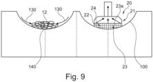
- the process of loosening the soil and removing the loosened soil is in Figure 8 and 9 for example in connection with a drill head 10 according to Figure 1 shown.
- the soil is loosened with drilling tools 12 and is located in the area of the respective drilling tools.
- flushing nozzles 32 are provided in the area of the respective drilling tools 12. These emit a flushing jet 130 which flushes the loosened soil 110 into the area of the borehole depth 140.
- the suction box 20 is moved with its opening 23 in this area.
- the transport medium jet 81 is then emitted in the opening area 23 via the nozzles 34 for emitting the transport medium jet 81, with which the loosened soil is accelerated into the opening 22 and thus moved to the flushing box 20 for removal, and/or is sucked off in the opening area 22 directly through the suction box 20.
- the movement/acceleration of the drilling cuttings into the suction box 20 can be additionally supported by mechanical tools.
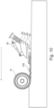
- Figure 10 shows the introduction of loosened soil into the suction box, the opening 29 or connection 30 to the conveying line 31 of which is provided behind the opening area 22.
- Mechanical support for the pickup by means of a pickup tool 33 is shown.
- the suction box 20 can be pivoted about a pivot point 36 via a cylinder 35.
- the nozzles 34 are not shown here.
- FIG 11 and 12 The introduction of loosened soil into the suction box 20 is shown, the opening 29 or connection 30 to the conveyor line 31 is provided in front of the opening area 22. Mechanical support for the pickup by means of a pickup tool 33 is shown.
- the suction box 20 can be pivoted about a pivot point 36 via a cylinder 35. This allows the suction box to be moved in the direction of arrow A, so that the distance 36 to the working face 100 changes.
- the arrangement of the nozzles 34 is shown.
- a first nozzle 34 is provided, which is directed in the direction of the deflection or receiving tool 33.
- a second nozzle 34' is provided, which is directed in the direction of the opening 29 and the connection 30.
- the loosened soil 110 is fed to the conveying medium 120 through the two nozzles 34, 34' and is conveyed away together with it.
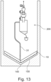
- the flow conveyed via the conveying line 31 consists of a combination of solid components (dissolved soil 110) and liquid and/or gaseous components. These are fed via the conveying line 31 to a processing unit 200 (see Figure 13 ).
- the components are separated from one another, for example by means of at least one cyclone, liquid and/or dust separators.
- the gaseous components are fed back into the drilling area (for example the shaft that has already been drilled).
- the liquid components are fed back to the nozzles 32, 34 34' if necessary or are transported out of the drilling area to the surface.
- the solid components are also transported out of the drilling area to the surface using suitable means.
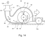
- a second embodiment of the invention according to the Figures 14-16 a mechanical acceleration input.
- an impact device 50 is provided, which is provided in the area of the suction box 20 towards the inside of the drill head 10 but can accelerate the loosened soil 110 in the area of the working face 100.
- a rotating element 51 is provided in a housing 57, on which a plurality of impact elements 52 are arranged in a circumferential manner, preferably movable via a joint 53.
- the impact elements 52 move on an impact circle 54 provided concentrically around the rotating element 51.
- the rotating element 51 is driven by a drive (not shown).
- Impact elements 52 strike loosened soil in an impact area 55, which is then introduced into the suction box 20 or its opening 23 in the impact direction 56.
- the accelerated loosened soil is then captured by the conveying medium 90 and conveyed away through the conveying line 31 with the conveying flow 120.
- Figure 15 and Figure 16 show different arrangement widths of the impact device 50 in connection with the flanks 18, 43 of the drill head 10.
- flanks 18, 43 as in Figure 16 shown above, compared to the representations in Figure 15 and Figure 16 can be made relatively steep and short at the bottom, so that under certain circumstances even flank flushing, here in the form of an air stream or in the form of clearing elements (not shown), can be omitted.
- Drill head 35 cylinder 11 Body 36 Pivot point 12 Drilling tool 37 Distance 12a Disk chisel 40 Wear element 12b Chisel 41 deepening 12c Roller chisel 42 Area 13 bottom 43 flank 14 Top 45 Connection 15 Ring section 16 bottom 50 Impact device 17 poor 51 Rotation element 18 flank 52 Impact element 19 Broaching tool 53 joint 20 Suction box 54 Impact circle 21 front 55 Impact area 22 Opening area 56 Impact direction 23 opening 57 Housing 23a Opening section 58 Rotation direction 24 Classification element 25 inner space 80 Transport medium 26 Lid 81 Transport medium jet 27 Floor 90 Pumping medium 28 Side wall 100 Face 29 opening 110 loosened soil 30 Connection 120 Flow rate 31 Conveyor line 130 Flushing jet 32 Rinse nozzle 140 Borehole deepest 33 Soil loosening tool / soil picking tool 200 processing 34, 34' jet
Landscapes
- Engineering & Computer Science (AREA)
- Mining & Mineral Resources (AREA)
- Life Sciences & Earth Sciences (AREA)
- Geology (AREA)
- Environmental & Geological Engineering (AREA)
- General Life Sciences & Earth Sciences (AREA)
- Geochemistry & Mineralogy (AREA)
- Mechanical Engineering (AREA)
- Physics & Mathematics (AREA)
- Fluid Mechanics (AREA)
- Earth Drilling (AREA)
Applications Claiming Priority (3)
| Application Number | Priority Date | Filing Date | Title |
|---|---|---|---|
| US201962878264P | 2019-07-24 | 2019-07-24 | |
| PCT/EP2020/070579 WO2021013846A2 (fr) | 2019-07-24 | 2020-07-21 | Tête de forage et procédé pour la réalisation d'un forage vertical dans le sol |
| EP20746138.5A EP4004331B1 (fr) | 2019-07-24 | 2020-07-21 | Tête de forage et procédé pour la réalisation d'un forage vertical dans le sol |
Related Parent Applications (1)
| Application Number | Title | Priority Date | Filing Date |
|---|---|---|---|
| EP20746138.5A Division EP4004331B1 (fr) | 2019-07-24 | 2020-07-21 | Tête de forage et procédé pour la réalisation d'un forage vertical dans le sol |
Publications (2)
| Publication Number | Publication Date |
|---|---|
| EP4411105A2 true EP4411105A2 (fr) | 2024-08-07 |
| EP4411105A3 EP4411105A3 (fr) | 2025-01-22 |
Family
ID=71786917
Family Applications (2)
| Application Number | Title | Priority Date | Filing Date |
|---|---|---|---|
| EP24165434.2A Pending EP4411105A3 (fr) | 2019-07-24 | 2020-07-21 | Tête de forage et procédé pour la réalisation d'un forage vertical dans le sol |
| EP20746138.5A Active EP4004331B1 (fr) | 2019-07-24 | 2020-07-21 | Tête de forage et procédé pour la réalisation d'un forage vertical dans le sol |
Family Applications After (1)
| Application Number | Title | Priority Date | Filing Date |
|---|---|---|---|
| EP20746138.5A Active EP4004331B1 (fr) | 2019-07-24 | 2020-07-21 | Tête de forage et procédé pour la réalisation d'un forage vertical dans le sol |
Country Status (8)
| Country | Link |
|---|---|
| US (1) | US12031385B2 (fr) |
| EP (2) | EP4411105A3 (fr) |
| CN (1) | CN114514359B (fr) |
| AU (1) | AU2020316928B2 (fr) |
| CA (1) | CA3148224C (fr) |
| ES (1) | ES2986095T3 (fr) |
| PL (1) | PL4004331T3 (fr) |
| WO (1) | WO2021013846A2 (fr) |
Families Citing this family (1)
| Publication number | Priority date | Publication date | Assignee | Title |
|---|---|---|---|---|
| WO2023035038A1 (fr) * | 2021-09-10 | 2023-03-16 | Optima Mining Systems Pty Ltd | Ensemble tête de coupe |
Citations (5)
| Publication number | Priority date | Publication date | Assignee | Title |
|---|---|---|---|---|
| US3384191A (en) | 1965-08-13 | 1968-05-21 | Reed Roller Bit Co | Drill bit |
| US4195700A (en) | 1978-08-14 | 1980-04-01 | Smith International, Inc. | Large diameter bit with sweep pickup |
| US4200160A (en) | 1978-03-13 | 1980-04-29 | Smith International, Inc. | Sweep pickup for a big hole bit |
| US4646853A (en) | 1984-07-31 | 1987-03-03 | The Robbins Company | Shaft boring machine and method |
| EP2597249B1 (fr) | 2011-11-24 | 2014-09-10 | Bauer Spezialtiefbau GmbH | Dispositif et procédé pour créer un forage vertical |
Family Cites Families (29)
| Publication number | Priority date | Publication date | Assignee | Title |
|---|---|---|---|---|
| FR1260016A (fr) * | 1959-12-12 | 1961-05-05 | Costa Fu Ernanio Flli | Procédé et dispositif pour l'exécution d'infrastructures en béton, béton armé ou similaires par forages parallèles, et coulée simultanée de béton ou de ciment |
| US3360061A (en) * | 1964-10-08 | 1967-12-26 | Otis Eng Co | Large well bore drilling apparatus |
| FR1567862A (fr) * | 1967-03-13 | 1969-05-23 | ||
| US3951220A (en) * | 1974-08-19 | 1976-04-20 | Vance Industries, Inc. | Archimedes spiral drill bit |
| US4105083A (en) * | 1977-06-09 | 1978-08-08 | Smith International, Inc. | Large diameter drill bit |
| GB2003211A (en) | 1977-07-08 | 1979-03-07 | Gladstone J | Sinking cased boreholes |
| US4296824A (en) * | 1978-06-29 | 1981-10-27 | Hughes Tool Company | Nozzle placement in large diameter earth boring bits |
| DE3039633C2 (de) * | 1980-10-21 | 1983-08-18 | Christensen, Inc., 84115 Salt Lake City, Utah | Drehbohrmeißel, insbesondere für Tiefbohrungen |
| US4540055A (en) * | 1983-06-10 | 1985-09-10 | Drumco | Drill bit assembly having improved operational life |
| US4492277A (en) * | 1983-02-22 | 1985-01-08 | Creighton Kenneth R | Hydraulic energy drill bit |
| US4534426A (en) * | 1983-08-24 | 1985-08-13 | Unique Oil Tools, Inc. | Packer weighted and pressure differential method and apparatus for Big Hole drilling |
| FR2566833B1 (fr) * | 1984-06-27 | 1986-11-14 | Inst Francais Du Petrole | Methode et perfectionnement aux outils de forage comportant des passages d'eau permettant une grande efficacite du nettoyage du front de taille |
| US4702325A (en) * | 1984-10-04 | 1987-10-27 | James Hipp | Apparatus and method for driving casing or conductor pipe |
| CA2007070C (fr) | 1990-01-03 | 1996-01-23 | Kirk Mcbride Sinclair | Systeme de forage a sec, a air comprime et a corps vertical pour roche dure |
| WO2005024173A1 (fr) * | 2003-09-08 | 2005-03-17 | Camstar Nominees Pty Ltd | Agencement de forage |
| US8028765B2 (en) * | 2008-04-23 | 2011-10-04 | Saudi Arabian Oil Company | Drill bit, drilling system, and related methods |
| EP2369127A1 (fr) * | 2010-03-09 | 2011-09-28 | Sandvik Intellectual Property AB | Taillant de fleuret, ensemble de forage et procédé de perçage et perçage de roche à percussion |
| EP2547866A1 (fr) | 2010-03-15 | 2013-01-23 | Vermeer Manufacturing Company | Appareil de forage à obturateur |
| US8615906B2 (en) | 2012-04-16 | 2013-12-31 | Pengo Corporation | Drilling bucket |
| EP2703596B1 (fr) * | 2012-08-31 | 2015-02-18 | BAUER Maschinen GmbH | Dispositif de forage et procédé d'établissement d'un forage |
| EP3268569B1 (fr) | 2015-03-12 | 2019-05-08 | Palmieri S.p.A. | Tête d'excavation |
| EP3103958A1 (fr) * | 2015-04-02 | 2016-12-14 | PSM S.p.A. | Ensemble de forage pour forer des puits dans des formations souterraines |
| PT3400371T (pt) * | 2016-02-01 | 2020-07-13 | Herrenknecht Ag | Dispositivo de perfuração de túnel e sistema para a remoção hidráulica de aparas, e sistema para a produção de uma pressão de fluido estável para um fluido de perfuração na região de uma roda de corte do dispositivo de perfuração de túnel |
| BE1023852B1 (nl) * | 2016-06-03 | 2017-08-14 | GeoSea N.V. | Inrichting en werkwijze voor het boren van een schacht met grote diameter in een ondergrond |
| US10947845B2 (en) * | 2016-09-21 | 2021-03-16 | Master Sinkers (Pty) Ltd | Shaft enlargement arrangement for a boring system |
| EP3336301B1 (fr) | 2016-12-19 | 2023-09-13 | BAUER Maschinen GmbH | Perforatrice rotative et procédé de fabrication d'un alésage |
| KR101762879B1 (ko) | 2017-02-21 | 2017-07-28 | 김인필 | 지반 굴착장치 |
| CN107386979B (zh) * | 2017-08-23 | 2023-09-26 | 中国石油大学(北京) | 内排屑脉冲射流降压钻头 |
| CN109611030B (zh) * | 2018-11-28 | 2019-11-29 | 中国石油大学(北京) | 排屑槽可变式射流钻头 |
-
2020
- 2020-07-21 US US17/628,852 patent/US12031385B2/en active Active
- 2020-07-21 WO PCT/EP2020/070579 patent/WO2021013846A2/fr not_active Ceased
- 2020-07-21 EP EP24165434.2A patent/EP4411105A3/fr active Pending
- 2020-07-21 EP EP20746138.5A patent/EP4004331B1/fr active Active
- 2020-07-21 CN CN202080062032.8A patent/CN114514359B/zh active Active
- 2020-07-21 AU AU2020316928A patent/AU2020316928B2/en active Active
- 2020-07-21 CA CA3148224A patent/CA3148224C/fr active Active
- 2020-07-21 PL PL20746138.5T patent/PL4004331T3/pl unknown
- 2020-07-21 ES ES20746138T patent/ES2986095T3/es active Active
Patent Citations (5)
| Publication number | Priority date | Publication date | Assignee | Title |
|---|---|---|---|---|
| US3384191A (en) | 1965-08-13 | 1968-05-21 | Reed Roller Bit Co | Drill bit |
| US4200160A (en) | 1978-03-13 | 1980-04-29 | Smith International, Inc. | Sweep pickup for a big hole bit |
| US4195700A (en) | 1978-08-14 | 1980-04-01 | Smith International, Inc. | Large diameter bit with sweep pickup |
| US4646853A (en) | 1984-07-31 | 1987-03-03 | The Robbins Company | Shaft boring machine and method |
| EP2597249B1 (fr) | 2011-11-24 | 2014-09-10 | Bauer Spezialtiefbau GmbH | Dispositif et procédé pour créer un forage vertical |
Also Published As
| Publication number | Publication date |
|---|---|
| CN114514359A (zh) | 2022-05-17 |
| AU2020316928A1 (en) | 2022-02-24 |
| WO2021013846A2 (fr) | 2021-01-28 |
| AU2020316928B2 (en) | 2026-04-09 |
| CN114514359B (zh) | 2025-03-21 |
| EP4004331A2 (fr) | 2022-06-01 |
| CA3148224C (fr) | 2024-01-23 |
| EP4004331C0 (fr) | 2024-03-27 |
| ES2986095T3 (es) | 2024-11-08 |
| PL4004331T3 (pl) | 2024-07-22 |
| CA3148224A1 (fr) | 2021-01-28 |
| EP4004331B1 (fr) | 2024-03-27 |
| EP4411105A3 (fr) | 2025-01-22 |
| US12031385B2 (en) | 2024-07-09 |
| US20230147209A1 (en) | 2023-05-11 |
| WO2021013846A3 (fr) | 2021-04-08 |
Similar Documents
| Publication | Publication Date | Title |
|---|---|---|
| DE1458675B2 (fr) | ||
| DE3543040C2 (fr) | ||
| DE2056598C3 (de) | Verfahren und Vorrichtung zur Erweiterung von durchgehenden, im wesentlichen horizontalen Bohrlöchern durch mechanisches Abtragen des umgebenden Gesteins | |
| EP4004341B1 (fr) | Tête de forage pour réaliser un forage dans le sol | |
| EP3087298A1 (fr) | Procédé et dispositif de pose de conduites sans tranchée | |
| DE1483857A1 (de) | Rollenbohrer | |
| EP4004331B1 (fr) | Tête de forage et procédé pour la réalisation d'un forage vertical dans le sol | |
| EP0909362B1 (fr) | Outil de forage pour procede de circulation inverse | |
| DE3239756C2 (de) | Verfahren und Vorrichtung zum Entfernen von Ablagerungen aus Kanälen | |
| DE2910323A1 (de) | Bohrwerkzeug, insbesondere gesteinsbohrer | |
| DE2541439A1 (de) | Strahlpumpe | |
| DE2837348C3 (de) | Vorrichtung zum Abteufen von Schächten | |
| DE4226492A1 (de) | Verfahren und vorrichtung zum vergroessern der wassertiefe eines gewaessers | |
| EP4001508A1 (fr) | Dispositif et procédé de nettoyage du sable | |
| DE3209611C1 (de) | Vollschnitt-Schachtbohrmaschine | |
| DE10237889C1 (de) | Vorrichtung zum Abtransport von Bohrgut aus dem Bohrkopfraum einer Vorrichtung zum Vortreiben von Bohrungen im Erdreich | |
| EP3763914B1 (fr) | Dispositif pour ménager un évidemment dans un sol | |
| EP0442589A1 (fr) | Procédé et dispositif pour créer des tranchées stables dans la terre et/ou le terrain non consolidé | |
| EP4198204A1 (fr) | Dispositif de fraisage et procédé de fraisage du sol | |
| DE102015101408A1 (de) | Verfahren und Vorrichtung zum Fördern von abgebautem Bodenmaterial aus dem Druckraum hinter die Druckwand einer SVM | |
| DE2362425C3 (de) | Vorrichtung zum Herstellen von Bohrungen im Erdreich | |
| EA048247B1 (ru) | Бурильная головка и способ для образования вертикальной скважины в грунте | |
| DE19645472A1 (de) | Verfahren und Vorrichtung zur Herstellung von standfesten Schlitzen im Erdreich, Lockergestein oder dergleichen | |
| DD300692A5 (de) | Verfahren zur Herstellung von standfesten Schlitzen im Erdreich, Lockergestein o. dgl. | |
| DE1583817A1 (de) | Verfahren und Vorrichtung fuer den Abbau in Bergwerken |
Legal Events
| Date | Code | Title | Description |
|---|---|---|---|
| PUAI | Public reference made under article 153(3) epc to a published international application that has entered the european phase |
Free format text: ORIGINAL CODE: 0009012 |
|
| STAA | Information on the status of an ep patent application or granted ep patent |
Free format text: STATUS: THE APPLICATION HAS BEEN PUBLISHED |
|
| AC | Divisional application: reference to earlier application |
Ref document number: 4004331 Country of ref document: EP Kind code of ref document: P |
|
| AK | Designated contracting states |
Kind code of ref document: A2 Designated state(s): AL AT BE BG CH CY CZ DE DK EE ES FI FR GB GR HR HU IE IS IT LI LT LU LV MC MK MT NL NO PL PT RO RS SE SI SK SM TR |
|
| RIC1 | Information provided on ipc code assigned before grant |
Ipc: E21B 21/12 20060101AFI20240829BHEP |
|
| PUAL | Search report despatched |
Free format text: ORIGINAL CODE: 0009013 |
|
| AK | Designated contracting states |
Kind code of ref document: A3 Designated state(s): AL AT BE BG CH CY CZ DE DK EE ES FI FR GB GR HR HU IE IS IT LI LT LU LV MC MK MT NL NO PL PT RO RS SE SI SK SM TR |
|
| RIC1 | Information provided on ipc code assigned before grant |
Ipc: E21B 21/12 20060101AFI20241217BHEP |
|
| STAA | Information on the status of an ep patent application or granted ep patent |
Free format text: STATUS: REQUEST FOR EXAMINATION WAS MADE |
|
| 17P | Request for examination filed |
Effective date: 20250722 |
|
| STAA | Information on the status of an ep patent application or granted ep patent |
Free format text: STATUS: EXAMINATION IS IN PROGRESS |
|
| 17Q | First examination report despatched |
Effective date: 20251201 |