EP4428005A1 - Caisse de véhicule ferroviaire avec zone d'entrée - Google Patents
Caisse de véhicule ferroviaire avec zone d'entrée Download PDFInfo
- Publication number
- EP4428005A1 EP4428005A1 EP24152178.0A EP24152178A EP4428005A1 EP 4428005 A1 EP4428005 A1 EP 4428005A1 EP 24152178 A EP24152178 A EP 24152178A EP 4428005 A1 EP4428005 A1 EP 4428005A1
- Authority
- EP
- European Patent Office
- Prior art keywords
- car body
- floor
- entry area
- area
- vehicle
- Prior art date
- Legal status (The legal status is an assumption and is not a legal conclusion. Google has not performed a legal analysis and makes no representation as to the accuracy of the status listed.)
- Withdrawn
Links
Images
Classifications
-
- B—PERFORMING OPERATIONS; TRANSPORTING
- B61—RAILWAYS
- B61D—BODY DETAILS OR KINDS OF RAILWAY VEHICLES
- B61D17/00—Construction details of vehicle bodies
- B61D17/04—Construction details of vehicle bodies with bodies of metal; with composite, e.g. metal and wood body structures
- B61D17/10—Floors
-
- B—PERFORMING OPERATIONS; TRANSPORTING
- B61—RAILWAYS
- B61D—BODY DETAILS OR KINDS OF RAILWAY VEHICLES
- B61D23/00—Construction of steps for railway vehicles
Definitions
- air springs or a level control system for the entire vehicle are usually used in the rail vehicles in question, particularly trams, metros, etc., with which the entire vehicle can be raised or lowered depending on the wear on the wheels and/or the vehicle's load, and the tolerance or distance between the entry edge of the entry area of the vehicle and the platform or platform edge can be adjusted accordingly.
- This is technically complex and therefore costly.
- the invention is based on the object of specifying a car body or a rail vehicle in which the setting of the tolerance or distance dimensions between the vehicle and the platform can be improved accordingly.
- a car body of a rail vehicle has at least one floor and at least one door, wherein the floor has at least one immovable and at least one movable part, wherein the at least one movable part of the floor forms an entry area in the area of the at least one door, between the at least one door and the immovable part of the floor of the car body, wherein the inclination of the entry area can be adjusted by means of an adjustment drive relative to the upper edge of the floor of the immovable part of the floor of the car body.
- the advantage of the device according to the invention is that when the vehicle is stopped, for example at a stop, the entire vehicle does not have to be raised or lowered, but the level, in particular the height of the vehicle's entry edge, i.e. its entry area, can be adjusted directly in relation to the platform or the upper edge of the platform.
- This level control is achieved by adjusting the incline of the entry area, which thereby becomes an entry ramp, using an adjustment drive. This ensures that passengers can get on and off safely and comfortably.
- the entry area is usually reset to the level of the top edge of the immovable part of the floor in order to ensure a flat vehicle floor in the vehicle, particularly for safety reasons for passengers.
- the reset of the entry area is triggered by closing or after closing the doors, for example automatically.
- the adjustment of the boarding area when or when stopping the vehicle, for example at a stop is advantageously carried out automatically by means of sensors placed accordingly, e.g. on the vehicle, which in particular detect the level of the platform at a stop.
- the resetting of the boarding area after stopping, for example when leaving a stop is also advantageously carried out automatically.
- the adjustment drive can be operated hydraulically by means of a hydraulic cylinder. This makes it possible to achieve high performance in a very small space and thus very easily achieve high pressures, which can also be precisely controlled.
- the adjustment drive can be operated electrically using an actuator. This makes it particularly advantageous to use the on-board electrical supply. This means that no auxiliary medium is required for the electromechanical adjustment and the "all electric car" concept can be implemented.
- the adjustment drive can be operated pneumatically by means of a pneumatic cylinder.
- the adjustment of the entry area is advantageously carried out very slowly, while at the same time correspondingly high pressures are present, so that the adjustment can also be carried out without any problems with passengers standing on the entry area and thus on the entry ramp.
- the boarding area is pivotally mounted at the transition point to the immovable part of the floor. This makes it even easier and therefore more cost-effective to adjust the boarding area to the level of the respective upper edge of the associated platform when the vehicle stops at a stop by setting the boarding area as an boarding ramp with an incline towards the platform, provided that the upper edge of the platform and the vehicle floor are not at the same height.
- the upper edge of the corresponding platform will be below the vehicle floor, so that the boarding ramp, i.e. the boarding area, is in relation to the upper edge the immovable part of the floor is adjusted so that the boarding ramp slopes towards the platform.
- the inclination of the boarding ramp is usually greatest when the vehicle is empty with new wheels, and decreases with increasing wear of the wheels and additional loading, for example from passengers.
- the vehicle is therefore preferably designed in such a way that the vehicle floor, when the wheels are worn and the vehicle is fully loaded, and the corresponding platforms at the stops are then essentially at the same height, so that in this state, ground-level boarding and alighting is possible without additional adjustment of the boarding ramp.
- the boarding ramp is adjusted so that it rises towards the platform, so that even in these cases, passengers can easily and conveniently board and alight.
- the entry area can be inclined up to an inclination of 12% relative to the upper edge of the immovable part of the floor of the car body towards the door.
- the entry area in the inclined state in the immediate area of the door has a height difference of up to 180 mm compared to the upper edge of the immovable part of the floor of the car body.
- the entrance area should preferably be inclined by up to 5% due to limited space, whereby the immediate In the area of the door, a height difference of up to 50 mm compared to the upper edge of the immovable part of the floor of the car body can be achieved and the boarding ramp is correspondingly shorter. Consequently, such a height difference between the upper edge of the platform and the vehicle floor can also be compensated accordingly.
- the entry area has an extension area which, as an extension of the entry area, can be extended outwards with respect to the car body.
- the exit area can be moved outwards in or as an extension of the boarding ramp either with a gradient corresponding to the boarding ramp, for example 5%, or horizontally, regardless of the boarding ramp gradient, and bridges the gap between the platform and the boarding area of the vehicle.
- the control i.e. the extension and retraction of the exit area, is advantageously carried out using the adjustment drive, which also controls the adjustment of the entry area.
- the extension area in combination with the adjustment of the entry area is therefore particularly advantageous for passengers with additional mobile objects, for example passengers with strollers, trolleys, etc., as well as passengers with limited mobility, for example passengers with or in wheelchairs, passengers with walkers, etc. for safe and comfortable entry and exit.
- a further preferred embodiment of the invention is a rail vehicle with at least one car body according to one of claims 1 to 9.
- the rail vehicle used is particularly preferably a tram.
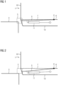
- Fig.1 shows a cross-sectional sketch of the entry area 9 of a car body 1 of a loaded rail vehicle with a high level of wear on the wheels, whereby the wheels are not shown here.
- the car body 1 of the rail vehicle is located according to Figure 1 at a stop with platform 3.
- the floor of the car body 1 is shown, which consists of a stationary part 8 and a movable part, the entry area 9.
- the level or height of the floor, in particular of the stationary part 8, is indicated by the upper edge of the floor 7.
- the entry area 9 is located in the area of the door 10, inside the car body 1, behind the door 10, and extends to the transition point 6.
- the entry area 9 is connected to the immovable part 8 of the floor of the car body 1 by means of the transition point 6 and is rotatably mounted.
- a sketched adjustment drive 11 is mounted, which is connected to the entry area 9 and with which the entry area 9, or in particular the inclination of the entry area 9, can be adjusted.
- the entry area 9 is usually set to the level of the upper edge 7 of the immovable part 8 of the floor.
- the adjustment drive 11 is advantageously operated electrically by means of an actuator, since in this way the vehicle's on-board electrical supply can be used for the electromechanical adjustment, thus no auxiliary medium is required and the "all electric car" concept can be implemented.
- the adjustment drive 11 can also be operated hydraulically by means of a hydraulic cylinder, pneumatically by means of a pneumatic cylinder or in another way.
- the height difference between the upper edge of the platform 3 and the upper edge of the floor 7 is relatively small, i.e. only a slight lowering or inclination of the entry area 9 towards the door 10 or platform 3 is necessary in order to compensate for the height difference between the upper edge of the platform 3 and the vehicle floor and to ensure safe and comfortable boarding and alighting of passengers via the boarding ramp sloping down to platform 3.
- the tolerance field 5 shows by way of example the scope within which the entry area 9 can be adjusted relative to the upper edge of the platform 3.
- the entry area 9 can advantageously be inclined up to an inclination of 12% compared to the upper floor edge 7 of the immovable part of the floor of the car body 1 to the door 10, whereby a height difference of up to 180 mm between the upper edge of the platform 3 and the upper edge of the vehicle floor 7 can be compensated.
- Fig.2 shows a cross-sectional sketch of the entry area 9 of the car body 1 from Fig.1 here in an unloaded state and with low wear of the wheels, which are also not shown here.
- the car body 1 is not yet as deep as in the Fig.1 shown, sunk so that the height difference between the upper edge of the platform 3 and the upper edge of the vehicle floor 7, as shown, is very large and is close to the maximum difference, whereby the inclination of the entry area 9, i.e. the entry ramp inclination, is correspondingly large and is also close to the maximum.
- This is very clearly visible in the tolerance field 5 shown as an example.
- the entry ramp inclination at the respective platform 3 decreases accordingly over time.
- An advantageous design for example with worn wheels and a fully loaded vehicle, then enables ground-level boarding and alighting without additional adjustment of the boarding ramp, since the upper edge of the floor 7 is then approximately at the same height as the corresponding platforms at the stops.
- the boarding area 9 can also be adjusted so that the boarding ramp rises in the direction of the platform 3, so that even in these cases, passengers can easily and conveniently get on and off the vehicle.
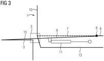
- Fig.3 shows a cross-sectional sketch of the entry area 9 of the car body 1 from Fig.1 with extended extension area 15.
- the entry area 9 has an extension area 15 which, as an extension of the entry area 9, can be extended outwards beyond the interior of the car body 1. As in Fig.3 As shown, this is possible until the exit area 15 is placed on the corresponding platform upper edge 3.
- the exit area 15 can be moved outwards in or as an extension of the boarding ramp either with a gradient corresponding to the boarding ramp of up to 12%, in particular 5%, or horizontally, regardless of the boarding ramp gradient, and thus bridges the gap between platform 3 and the boarding area 9 of the vehicle while it is stopped at a stop.
- the exit area 15 is advantageously also controlled by the adjustment drive 11.
- the exit area 15 in combination with the setting of the entry area 9 is therefore particularly advantageous for passengers with additional mobile objects, for example passengers with strollers, trolleys, etc., as well as for passengers with reduced mobility, for example passengers with or in wheelchairs, passengers with rollators, etc. for safe and comfortable entry and exit.
Landscapes
- Engineering & Computer Science (AREA)
- Mechanical Engineering (AREA)
- Life Sciences & Earth Sciences (AREA)
- Wood Science & Technology (AREA)
- Platform Screen Doors And Railroad Systems (AREA)
Applications Claiming Priority (1)
| Application Number | Priority Date | Filing Date | Title |
|---|---|---|---|
| DE102023202100.5A DE102023202100A1 (de) | 2023-03-09 | 2023-03-09 | Wagenkasten eines Schienenfahrzeugs mit Einstiegsbereich |
Publications (1)
| Publication Number | Publication Date |
|---|---|
| EP4428005A1 true EP4428005A1 (fr) | 2024-09-11 |
Family
ID=89619359
Family Applications (1)
| Application Number | Title | Priority Date | Filing Date |
|---|---|---|---|
| EP24152178.0A Withdrawn EP4428005A1 (fr) | 2023-03-09 | 2024-01-16 | Caisse de véhicule ferroviaire avec zone d'entrée |
Country Status (2)
| Country | Link |
|---|---|
| EP (1) | EP4428005A1 (fr) |
| DE (1) | DE102023202100A1 (fr) |
Cited By (1)
| Publication number | Priority date | Publication date | Assignee | Title |
|---|---|---|---|---|
| CN119928927A (zh) * | 2025-02-21 | 2025-05-06 | 中车株洲电力机车有限公司 | 一种轨道车辆车门处地板调节装置及调节方法 |
Citations (5)
| Publication number | Priority date | Publication date | Assignee | Title |
|---|---|---|---|---|
| WO2007074145A1 (fr) * | 2005-12-23 | 2007-07-05 | Bombardier Transportation Gmbh | Vehicule ferroviaire transformable |
| EP1808352B1 (fr) * | 2006-01-12 | 2009-03-11 | Siemens Aktiengesellschaft | Véhicule ferroviaire ayant au moins une zone de l'accès et une construction de plancher modulaire |
| US20170334464A1 (en) * | 2014-11-19 | 2017-11-23 | Alstom Transport Technologies | Railway vehicle with a movable, vertical gap bridging entry threshold |
| EP3583011B1 (fr) * | 2017-04-18 | 2021-10-27 | Siemens Mobility GmbH | Dispositif et procédé de réalisation d'un accès à niveau pour différentes hauteurs de quais |
| WO2022016218A1 (fr) * | 2020-07-22 | 2022-01-27 | Mircea Eugen Virgil Cociuban The Trustee For Rofraus Trust | Rampe d'accès mécanisée descendante (d-mar) |
Family Cites Families (2)
| Publication number | Priority date | Publication date | Assignee | Title |
|---|---|---|---|---|
| DE19503079C2 (de) | 1995-02-01 | 1998-07-09 | Deutsche Waggonbau Ag | Überfahrrampe für Rollstuhlfahrer in Fahrzeugen mit Niederflureinstiegen, insbesondere Reisezugwagen |
| DE20104221U1 (de) | 2001-03-09 | 2001-07-19 | Schliess- und Sicherungssysteme GmbH, 99974 Mühlhausen | Einstieg für Schienenfahrzeuge |
-
2023
- 2023-03-09 DE DE102023202100.5A patent/DE102023202100A1/de not_active Withdrawn
-
2024
- 2024-01-16 EP EP24152178.0A patent/EP4428005A1/fr not_active Withdrawn
Patent Citations (5)
| Publication number | Priority date | Publication date | Assignee | Title |
|---|---|---|---|---|
| WO2007074145A1 (fr) * | 2005-12-23 | 2007-07-05 | Bombardier Transportation Gmbh | Vehicule ferroviaire transformable |
| EP1808352B1 (fr) * | 2006-01-12 | 2009-03-11 | Siemens Aktiengesellschaft | Véhicule ferroviaire ayant au moins une zone de l'accès et une construction de plancher modulaire |
| US20170334464A1 (en) * | 2014-11-19 | 2017-11-23 | Alstom Transport Technologies | Railway vehicle with a movable, vertical gap bridging entry threshold |
| EP3583011B1 (fr) * | 2017-04-18 | 2021-10-27 | Siemens Mobility GmbH | Dispositif et procédé de réalisation d'un accès à niveau pour différentes hauteurs de quais |
| WO2022016218A1 (fr) * | 2020-07-22 | 2022-01-27 | Mircea Eugen Virgil Cociuban The Trustee For Rofraus Trust | Rampe d'accès mécanisée descendante (d-mar) |
Cited By (2)
| Publication number | Priority date | Publication date | Assignee | Title |
|---|---|---|---|---|
| CN119928927A (zh) * | 2025-02-21 | 2025-05-06 | 中车株洲电力机车有限公司 | 一种轨道车辆车门处地板调节装置及调节方法 |
| CN119928927B (zh) * | 2025-02-21 | 2025-10-17 | 中车株洲电力机车有限公司 | 一种轨道车辆车门处地板调节装置及调节方法 |
Also Published As
| Publication number | Publication date |
|---|---|
| DE102023202100A1 (de) | 2024-09-12 |
Similar Documents
| Publication | Publication Date | Title |
|---|---|---|
| EP0416539B1 (fr) | Dispositif d'accès pour véhicules automobiles, en particulier pour autobus | |
| DE112014000985B4 (de) | Hebesäule, Hebesystem und Verfahren zum Heben eines Fahrzeugs, wie etwa eines Schienenfahrzeugs | |
| DE102017107059A1 (de) | Schienenschleif-Vorrichtung | |
| EP3868626B1 (fr) | Véhicule de transport des personnes | |
| DE4329614C2 (de) | Einstieg für Schienenfahrzeuge | |
| DE69927010T2 (de) | Hebevorrichtung für eisenbahnfahrzeuge | |
| EP2228278A1 (fr) | Wagon | |
| EP4428005A1 (fr) | Caisse de véhicule ferroviaire avec zone d'entrée | |
| AT515195A4 (de) | Bewegliches Trittbrett | |
| DE9421209U1 (de) | Doppelstöckiges Schienenfahrzeug zur Beförderung von Personen im Nah- und Fernverkehr auf Strecken mit unterschiedlichen Bahnsteighöhen | |
| DE4137450A1 (de) | Ein- oder ausstiegstrittsystem fuer fahrzeuge | |
| DE19531284A1 (de) | Schienenfahrzeug für den Personenverkehr | |
| DE102009024510A1 (de) | Schienenfahrzeug und Verfahren zum Betrieb eines Schienenfahrzeugs | |
| AT512012B1 (de) | Passagierschienenfahrzeug | |
| DE10113074A1 (de) | Vorrichtung und Verfahren zum Überbrücken von Niveauunterschieden | |
| DE102017214308A1 (de) | Fahrzeug zur Personenbeförderung, insbesondere ein Multigelenk-Schienenfahrzeug und Einrichtung zur Anpassung der Einstiegshöhe | |
| EP2792568B2 (fr) | Véhicule sur rails en plusieurs parties | |
| EP1034765A2 (fr) | Dispositif pour faciliter l'entrée et la sortie d'un véhicule des transports publics en particulier un véhicule approchant un perron | |
| EP3583011B1 (fr) | Dispositif et procédé de réalisation d'un accès à niveau pour différentes hauteurs de quais | |
| EP3081450A1 (fr) | Véhicule de transport | |
| DE102016207263B3 (de) | Fahrzeug, insbesondere Schienenfahrzeug, und Verfahren zu dessen Betrieb | |
| DE19949201C2 (de) | System zum Auf- und Abladen von Landfahrzeugen für deren Transport auf dem Schienenweg | |
| EP3737598B1 (fr) | Caisson de pont de véhicule et véhicule ferroviaire à plusieurs unités | |
| DE102021212984A1 (de) | Fahrzeug mit Rampenteil an einer Karosserieöffnung | |
| WO2022144174A1 (fr) | Dispositif de maintenance pour véhicule et procédé d'utilisation d'un dispositif de maintenance |
Legal Events
| Date | Code | Title | Description |
|---|---|---|---|
| PUAI | Public reference made under article 153(3) epc to a published international application that has entered the european phase |
Free format text: ORIGINAL CODE: 0009012 |
|
| STAA | Information on the status of an ep patent application or granted ep patent |
Free format text: STATUS: THE APPLICATION HAS BEEN PUBLISHED |
|
| AK | Designated contracting states |
Kind code of ref document: A1 Designated state(s): AL AT BE BG CH CY CZ DE DK EE ES FI FR GB GR HR HU IE IS IT LI LT LU LV MC ME MK MT NL NO PL PT RO RS SE SI SK SM TR |
|
| STAA | Information on the status of an ep patent application or granted ep patent |
Free format text: STATUS: THE APPLICATION IS DEEMED TO BE WITHDRAWN |
|
| 18D | Application deemed to be withdrawn |
Effective date: 20250312 |