EP4474804A1 - Dispositif d'inspection et procédé d'inspection - Google Patents
Dispositif d'inspection et procédé d'inspection Download PDFInfo
- Publication number
- EP4474804A1 EP4474804A1 EP22924090.8A EP22924090A EP4474804A1 EP 4474804 A1 EP4474804 A1 EP 4474804A1 EP 22924090 A EP22924090 A EP 22924090A EP 4474804 A1 EP4474804 A1 EP 4474804A1
- Authority
- EP
- European Patent Office
- Prior art keywords
- inspection
- ray
- rays
- ray detector
- foreign substance
- Prior art date
- Legal status (The legal status is an assumption and is not a legal conclusion. Google has not performed a legal analysis and makes no representation as to the accuracy of the status listed.)
- Pending
Links
Images





Classifications
-
- G—PHYSICS
- G01—MEASURING; TESTING
- G01N—INVESTIGATING OR ANALYSING MATERIALS BY DETERMINING THEIR CHEMICAL OR PHYSICAL PROPERTIES
- G01N23/00—Investigating or analysing materials by the use of wave or particle radiation, e.g. X-rays or neutrons, not covered by groups G01N3/00 – G01N17/00, G01N21/00 or G01N22/00
- G01N23/02—Investigating or analysing materials by the use of wave or particle radiation, e.g. X-rays or neutrons, not covered by groups G01N3/00 – G01N17/00, G01N21/00 or G01N22/00 by transmitting the radiation through the material
- G01N23/04—Investigating or analysing materials by the use of wave or particle radiation, e.g. X-rays or neutrons, not covered by groups G01N3/00 – G01N17/00, G01N21/00 or G01N22/00 by transmitting the radiation through the material and forming images of the material
-
- G—PHYSICS
- G01—MEASURING; TESTING
- G01N—INVESTIGATING OR ANALYSING MATERIALS BY DETERMINING THEIR CHEMICAL OR PHYSICAL PROPERTIES
- G01N23/00—Investigating or analysing materials by the use of wave or particle radiation, e.g. X-rays or neutrons, not covered by groups G01N3/00 – G01N17/00, G01N21/00 or G01N22/00
- G01N23/02—Investigating or analysing materials by the use of wave or particle radiation, e.g. X-rays or neutrons, not covered by groups G01N3/00 – G01N17/00, G01N21/00 or G01N22/00 by transmitting the radiation through the material
- G01N23/06—Investigating or analysing materials by the use of wave or particle radiation, e.g. X-rays or neutrons, not covered by groups G01N3/00 – G01N17/00, G01N21/00 or G01N22/00 by transmitting the radiation through the material and measuring the absorption
- G01N23/083—Investigating or analysing materials by the use of wave or particle radiation, e.g. X-rays or neutrons, not covered by groups G01N3/00 – G01N17/00, G01N21/00 or G01N22/00 by transmitting the radiation through the material and measuring the absorption the radiation being X-rays
-
- G—PHYSICS
- G01—MEASURING; TESTING
- G01N—INVESTIGATING OR ANALYSING MATERIALS BY DETERMINING THEIR CHEMICAL OR PHYSICAL PROPERTIES
- G01N23/00—Investigating or analysing materials by the use of wave or particle radiation, e.g. X-rays or neutrons, not covered by groups G01N3/00 – G01N17/00, G01N21/00 or G01N22/00
- G01N23/02—Investigating or analysing materials by the use of wave or particle radiation, e.g. X-rays or neutrons, not covered by groups G01N3/00 – G01N17/00, G01N21/00 or G01N22/00 by transmitting the radiation through the material
- G01N23/06—Investigating or analysing materials by the use of wave or particle radiation, e.g. X-rays or neutrons, not covered by groups G01N3/00 – G01N17/00, G01N21/00 or G01N22/00 by transmitting the radiation through the material and measuring the absorption
- G01N23/18—Investigating the presence of flaws defects or foreign matter
-
- G—PHYSICS
- G01—MEASURING; TESTING
- G01N—INVESTIGATING OR ANALYSING MATERIALS BY DETERMINING THEIR CHEMICAL OR PHYSICAL PROPERTIES
- G01N23/00—Investigating or analysing materials by the use of wave or particle radiation, e.g. X-rays or neutrons, not covered by groups G01N3/00 – G01N17/00, G01N21/00 or G01N22/00
- G01N23/20—Investigating or analysing materials by the use of wave or particle radiation, e.g. X-rays or neutrons, not covered by groups G01N3/00 – G01N17/00, G01N21/00 or G01N22/00 by using diffraction of the radiation by the materials, e.g. for investigating crystal structure; by using scattering of the radiation by the materials, e.g. for investigating non-crystalline materials; by using reflection of the radiation by the materials
- G01N23/20008—Constructional details of analysers, e.g. characterised by X-ray source, detector or optical system; Accessories therefor; Preparing specimens therefor
-
- G—PHYSICS
- G01—MEASURING; TESTING
- G01N—INVESTIGATING OR ANALYSING MATERIALS BY DETERMINING THEIR CHEMICAL OR PHYSICAL PROPERTIES
- G01N23/00—Investigating or analysing materials by the use of wave or particle radiation, e.g. X-rays or neutrons, not covered by groups G01N3/00 – G01N17/00, G01N21/00 or G01N22/00
- G01N23/22—Investigating or analysing materials by the use of wave or particle radiation, e.g. X-rays or neutrons, not covered by groups G01N3/00 – G01N17/00, G01N21/00 or G01N22/00 by measuring secondary emission from the material
-
- G—PHYSICS
- G01—MEASURING; TESTING
- G01N—INVESTIGATING OR ANALYSING MATERIALS BY DETERMINING THEIR CHEMICAL OR PHYSICAL PROPERTIES
- G01N23/00—Investigating or analysing materials by the use of wave or particle radiation, e.g. X-rays or neutrons, not covered by groups G01N3/00 – G01N17/00, G01N21/00 or G01N22/00
- G01N23/22—Investigating or analysing materials by the use of wave or particle radiation, e.g. X-rays or neutrons, not covered by groups G01N3/00 – G01N17/00, G01N21/00 or G01N22/00 by measuring secondary emission from the material
- G01N23/2206—Combination of two or more measurements, at least one measurement being that of secondary emission, e.g. combination of secondary electron [SE] measurement and back-scattered electron [BSE] measurement
-
- G—PHYSICS
- G01—MEASURING; TESTING
- G01N—INVESTIGATING OR ANALYSING MATERIALS BY DETERMINING THEIR CHEMICAL OR PHYSICAL PROPERTIES
- G01N23/00—Investigating or analysing materials by the use of wave or particle radiation, e.g. X-rays or neutrons, not covered by groups G01N3/00 – G01N17/00, G01N21/00 or G01N22/00
- G01N23/22—Investigating or analysing materials by the use of wave or particle radiation, e.g. X-rays or neutrons, not covered by groups G01N3/00 – G01N17/00, G01N21/00 or G01N22/00 by measuring secondary emission from the material
- G01N23/223—Investigating or analysing materials by the use of wave or particle radiation, e.g. X-rays or neutrons, not covered by groups G01N3/00 – G01N17/00, G01N21/00 or G01N22/00 by measuring secondary emission from the material by irradiating the sample with X-rays or gamma-rays and by measuring X-ray fluorescence
-
- G—PHYSICS
- G21—NUCLEAR PHYSICS; NUCLEAR ENGINEERING
- G21K—HANDLING OF PARTICLES OR IONISING RADIATION NOT OTHERWISE PROVIDED FOR; IRRADIATION DEVICES; GAMMA RAY OR X-RAY MICROSCOPES
- G21K7/00—Gamma- or X-ray microscopes
-
- H—ELECTRICITY
- H01—ELECTRIC ELEMENTS
- H01J—ELECTRIC DISCHARGE TUBES OR DISCHARGE LAMPS
- H01J35/00—X-ray tubes
- H01J35/02—Details
- H01J35/14—Arrangements for concentrating, focusing, or directing the cathode ray
- H01J35/153—Spot position control
-
- H—ELECTRICITY
- H01—ELECTRIC ELEMENTS
- H01J—ELECTRIC DISCHARGE TUBES OR DISCHARGE LAMPS
- H01J35/00—X-ray tubes
- H01J35/02—Details
- H01J35/16—Vessels; Containers; Shields associated therewith
- H01J35/18—Windows
- H01J35/186—Windows used as targets or X-ray converters
-
- G—PHYSICS
- G01—MEASURING; TESTING
- G01N—INVESTIGATING OR ANALYSING MATERIALS BY DETERMINING THEIR CHEMICAL OR PHYSICAL PROPERTIES
- G01N2223/00—Investigating materials by wave or particle radiation
- G01N2223/03—Investigating materials by wave or particle radiation by transmission
- G01N2223/04—Investigating materials by wave or particle radiation by transmission and measuring absorption
-
- G—PHYSICS
- G01—MEASURING; TESTING
- G01N—INVESTIGATING OR ANALYSING MATERIALS BY DETERMINING THEIR CHEMICAL OR PHYSICAL PROPERTIES
- G01N2223/00—Investigating materials by wave or particle radiation
- G01N2223/05—Investigating materials by wave or particle radiation by diffraction, scatter or reflection
- G01N2223/052—Investigating materials by wave or particle radiation by diffraction, scatter or reflection reflection
-
- G—PHYSICS
- G01—MEASURING; TESTING
- G01N—INVESTIGATING OR ANALYSING MATERIALS BY DETERMINING THEIR CHEMICAL OR PHYSICAL PROPERTIES
- G01N2223/00—Investigating materials by wave or particle radiation
- G01N2223/07—Investigating materials by wave or particle radiation secondary emission
- G01N2223/071—Investigating materials by wave or particle radiation secondary emission combination of measurements, at least 1 secondary emission
-
- G—PHYSICS
- G01—MEASURING; TESTING
- G01N—INVESTIGATING OR ANALYSING MATERIALS BY DETERMINING THEIR CHEMICAL OR PHYSICAL PROPERTIES
- G01N2223/00—Investigating materials by wave or particle radiation
- G01N2223/07—Investigating materials by wave or particle radiation secondary emission
- G01N2223/076—X-ray fluorescence
-
- G—PHYSICS
- G01—MEASURING; TESTING
- G01N—INVESTIGATING OR ANALYSING MATERIALS BY DETERMINING THEIR CHEMICAL OR PHYSICAL PROPERTIES
- G01N2223/00—Investigating materials by wave or particle radiation
- G01N2223/10—Different kinds of radiation or particles
- G01N2223/101—Different kinds of radiation or particles electromagnetic radiation
- G01N2223/1016—X-ray
-
- G—PHYSICS
- G01—MEASURING; TESTING
- G01N—INVESTIGATING OR ANALYSING MATERIALS BY DETERMINING THEIR CHEMICAL OR PHYSICAL PROPERTIES
- G01N2223/00—Investigating materials by wave or particle radiation
- G01N2223/20—Sources of radiation
-
- G—PHYSICS
- G01—MEASURING; TESTING
- G01N—INVESTIGATING OR ANALYSING MATERIALS BY DETERMINING THEIR CHEMICAL OR PHYSICAL PROPERTIES
- G01N2223/00—Investigating materials by wave or particle radiation
- G01N2223/20—Sources of radiation
- G01N2223/204—Sources of radiation source created from radiated target
-
- G—PHYSICS
- G01—MEASURING; TESTING
- G01N—INVESTIGATING OR ANALYSING MATERIALS BY DETERMINING THEIR CHEMICAL OR PHYSICAL PROPERTIES
- G01N2223/00—Investigating materials by wave or particle radiation
- G01N2223/30—Accessories, mechanical or electrical features
- G01N2223/32—Accessories, mechanical or electrical features adjustments of elements during operation
-
- G—PHYSICS
- G01—MEASURING; TESTING
- G01N—INVESTIGATING OR ANALYSING MATERIALS BY DETERMINING THEIR CHEMICAL OR PHYSICAL PROPERTIES
- G01N2223/00—Investigating materials by wave or particle radiation
- G01N2223/60—Specific applications or type of materials
- G01N2223/643—Specific applications or type of materials object on conveyor
-
- G—PHYSICS
- G01—MEASURING; TESTING
- G01N—INVESTIGATING OR ANALYSING MATERIALS BY DETERMINING THEIR CHEMICAL OR PHYSICAL PROPERTIES
- G01N2223/00—Investigating materials by wave or particle radiation
- G01N2223/60—Specific applications or type of materials
- G01N2223/652—Specific applications or type of materials impurities, foreign matter, trace amounts
Definitions
- the present invention relates to an inspection apparatus and an inspection method.
- PTL 1 describes a high-resolution X-ray microscope apparatus with an X-ray fluorescence analysis function, that includes a detector configured to detect fluorescent X-rays which are generated from a sample by focusing electron beams on an X-ray generation target by an object lens and irradiating the sample with X-rays generated from the target, and an analysis unit configured to analyze the fluorescent X-rays from the detection result of the detector.
- PTL 1 also describes an arrangement in which the whole detector or part of the detector is incorporated in the magnetic circuit of the object lens.
- a separator for maintaining insulation in the battery may break due to a vibration of the foreign substance after shipping of the battery.
- the battery may be short-circuited and ignite or explode.
- X-ray Fluorescence to also be called XRF
- TXRF Grazing Incidence X-ray Fluorescence
- X-ray Fluorescence the element of a sample substrate is also excited.
- Grazing Incidence X-ray Fluorescence incident X-rays are scattered due to a foreign substance. Therefore, in these measurement methods, there is a problem that the intensity ratio of the generated fluorescent X-rays becomes low due to the foreign substance.
- the present invention has as its object to provide a technique advantageous in detecting a foreign substance existing on an inspection target surface with high sensitivity.
- a first aspect of the present invention provides an inspection apparatus for inspecting an inspection target surface arranged on an inspection plane, comprising: an X-ray generation tube having a target including an X-ray generation portion that generates X-rays by irradiation with an electron beam, and configured to emit X-rays to the inspection plane; and an X-ray detector configured to detect X-rays emitted from a foreign substance existing on the inspection target surface irradiated with the X-rays from the X-ray generation portion and totally reflected by the inspection target surface, wherein the X-ray detector has an energy resolution not less than 1 keV or the X-ray detector has no energy analysis function.
- a second aspect of the present invention provides an inspection method of inspecting an inspection target surface arranged on an inspection plane, comprising: an X-ray detection step of emitting X-rays to the inspection plane and detecting, by an X-ray detector, X-rays emitted from a foreign substance existing on the inspection target surface and totally reflected by the inspection target surface; and a processing step of processing an output of the X-ray detector, wherein the X-ray detector has an energy resolution not less than 1 keV or the X-ray detector has no energy analysis function.
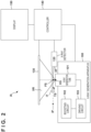
- Fig. 1 schematically shows the arrangement of an inspection apparatus IA according to the first embodiment of the present disclosure.
- the inspection apparatus IA can be formed as, for example, an inspection apparatus that inspects an inspection target surface TS arranged on an inspection plane IP.
- the inspection plane IP is a plane on which the inspection target surface TS should be arranged, and the inspection target surface TS is one surface of an inspection target object IT.
- the inspection apparatus IA can include an X-ray generation tube 101.
- the X-ray generation tube 101 has a target (not shown) including an X-ray generation portion XG that generates X-rays by irradiation with an electron beam, and emits X-rays XR to the inspection plane IP.
- a foreign substance FS irradiated with the X-rays XR from the X-ray generation portion XG generates X-rays corresponding to a material forming the foreign substance FS, and such X-rays are also called fluorescent X-rays or characteristic X-rays.
- Some of the X-rays generated by the foreign substance FS irradiated with the X-rays XR are totally reflected by the inspection target surface TS.
- the X-rays emitted from the foreign substance FS and totally reflected by the inspection target surface TS are represented as X-rays XF.
- the inspection apparatus IA can include an X-ray detector 120.
- the X-ray detector 120 can be configured to detect the X-rays XF emitted from the foreign substance FS existing on the inspection target surface TS irradiated with the X-rays XR from the X-ray generation portion XG and totally reflected by the inspection target surface TS.
- the inspection apparatus IA can further include a processor that performs processing of detecting the foreign substance FS based on an output from the X-ray detector 120.
- the processor can further perform processing of specifying the material forming the foreign substance FS based on the output from the X-ray detector 120.
- the processor can be implemented by, for example, a controller that controls the operation of the inspection apparatus IA.
- the inspection apparatus IA can include an X-ray generation apparatus 100, the X-ray detector 120, and a controller 140.
- the X-ray generation apparatus 100 can include the X-ray generation tube 101 and a driving circuit 103 that drives the X-ray generation tube 101.
- the X-ray generation apparatus 100 can further include a boosting circuit 102 that supplies a boosted voltage to the driving circuit 103.
- the X-ray generation apparatus 100 can further include a storage container (not shown) that stores the X-ray generation tube 101, the driving circuit 103, and the boosting circuit 102, and the storage container can be filled with an insulating fluid such as insulating oil.
- the controller 140 can be configured to control the X-ray generation apparatus 100 and the X-ray detector 120.
- the controller 140 can have the function of the above-described processor. More specifically, the controller 140 can perform processing of detecting the foreign substance FS based on the output from the X-ray detector 120. Furthermore, the controller 140 can perform processing of specifying the material forming the foreign substance FS based on the output from the X-ray detector 120.
- the controller 140 can be formed by, for example, a PLD (an abbreviation of Programmable Logic Device) such as an FPGA(an abbreviation of Field Programmable Gate Array), an ASIC (an abbreviation of Application Specific Integrated Circuit), a general-purpose or dedicated computer installed with a program, or a combination of all or some of these components.
- a PLD an abbreviation of Programmable Logic Device
- FPGA an abbreviation of Field Programmable Gate Array
- ASIC an abbreviation of Application Specific Integrated Circuit
- a general-purpose or dedicated computer installed with a program or a combination of all or some of these components.
- the inspection apparatus IA may further include an X-ray detection panel 130 that detects X-rays emitted from the X-ray generation portion XG and transmitted through the inspection target object IT having the inspection target surface TS.
- the controller 140 can be configured to generate an image (a transmission image of the inspection target object IT) of the X-rays transmitted through the inspection target object IT based on an output from the X-ray detection panel 130 and detect the foreign substance FS existing on the inspection target surface TS based on the image. It is possible to detect a foreign substance existing inside the inspection target object IT and a foreign substance existing on a surface on the opposite side of the inspection target surface TS using the X-ray detection panel 130.
- the controller 140 can be configured to detect the existence of the foreign substance FS and also detect the position and/or size of the foreign substance FS.
- the X-ray detection panel 130 in addition to the X-ray detector 120, the foreign substance FS that cannot be detected by the X-ray detector 120 can be detected by the X-ray detection panel 130, thereby making it possible to improve the accuracy of detection of the foreign substance FS.
- the inspection apparatus IA that acquires a transmission image and detects a foreign substance using X-rays emitted from one X-ray generation tube is advantageous in reducing the size and the cost.
- the inspection apparatus IA may further include a display 150, and the controller 140 can be configured to display, on the display 150, information indicating the constituent material of the foreign substance FS specified based on the output from the X-ray detector 120.
- the controller 140 can further be configured to display, on the display 150, the transmission image of the inspection target object IT generated based on the output from the X-ray detection panel 130.
- the controller 140 can be configured to display, on the display 150, information indicating the position and/or size of the foreign substance detected based on the output from the X-ray detection panel 130.
- the controller 140 may be formed by a single unit or may be divided into a plurality of units.
- Fig. 3 schematically shows an example of the arrangement of the X-ray generation tube 101.
- the X-ray generation tube 101 can include an electron gun EG, an anode 93 having a target 933 including the X-ray generation portion XG that generates X-rays when electrons from the electron gun EG collide, and an insulating tube 92.
- the anode 93 can be arranged to close one of the two opening ends of the insulating tube 92
- a closing member 91 including the electron gun EG can be arranged to close the other of the two opening ends of the insulating tube 92.
- a deflector 94 that deflects the flow (electron beam) of electrons from the electron gun EG may be arranged outside the insulating tube 92.
- the X-ray generation tube 101 shown in Fig. 3 is an example of a sealed transmission type X-ray generation tube in which the internal space of the insulating tube 92 is maintained in a vacuum state and X-rays are transmitted through the target 933 and a target holding plate 932 (to be described later).
- an unsealed open type or non-transmission reflection type X-ray generation tube may be adopted as the X-ray generation tube 101.
- the deflector 94 can be arranged outside the X-ray generation tube 101. With respect to a direction parallel to an axis AX of the X-ray generation tube 101, the deflector 94 can be provided between the anode 93 and a cathode (not shown). In an example, with respect to the direction parallel to the axis AX of the X-ray generation tube 101, the deflector 94 is provided between the electron gun EG and the target 933. More specifically, a virtual plane 97 crossing the deflector 94 can be located in a space sandwiched between a virtual plane 95 contacting the distal end of the electron gun EG and a virtual plane 96 contacting part of the target 933. The virtual planes 95, 96, and 97 are planes orthogonal to the axis AX of the X-ray generation tube 101.
- the anode 93 can include the target 933, the target holding plate 932 that holds the target 933, and an electrode 931 that holds the target holding plate 932.
- the electrode 931 is electrically connected to the target 933 and can give a potential to the target 933.
- the target 933 generates X-rays when electrons (electron beam) emitted from the electron gun EG collide against the target 933.
- the X-ray generation portion XG is a portion of the surface of the target 933, against which the electrons (electron beam) collide.
- the X-rays generated by the X-ray generation portion XG are transmitted through the target holding plate 932 and emitted to the outside of the X-ray generation tube 101.
- the anode 93 can be maintained at, for example, the ground potential but may be maintained at another potential.
- the target 933 is made of a metal material.
- the target 933 is desirably made of a material having a high melting point, for example, tungsten, tantalum, molybdenum, or the like, which contributes to improvement of X-ray generation efficiency.
- the target holding plate 932 can be made of a material that readily passes X-rays, for example, beryllium, diamond, or the like.
- the target holding plate 932 is desirably made of diamond. This can decrease the thickness of the target holding plate 932 while maintaining the strength of the target holding plate 932, and can decrease the distance between the inspection plane IP (inspection target surface TS) and the target 933 (X-ray generation portion XG).
- the thickness of the target holding plate 932 is desirably thin.
- the optimum thickness of the target holding plate 932 is desirably used.
- Fig. 3 is not intended to show the relationship between the thickness of the target 933 and that of the target holding plate 932.
- the thickness of the target 933 may be several ⁇ m, and the thickness of the target holding plate 932 may be several hundred ⁇ m.
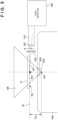
- Fig. 4 is an enlarged schematic view of part of the inspection apparatus IA shown in Fig. 2 .
- the foreign substance FS can exist on the inspection target surface TS.
- the X-rays (characteristic X-rays) XF that are emitted from the foreign substance FS so as to be totally reflected by the inspection target surface TS and are totally reflected by the inspection target surface TS enter an X-ray receiving portion 121 of the X-ray detector 120.
- fluorescent X-rays that can be generated from the inspection target object IT by irradiation with the X-rays XR from the X-ray generation portion XG hardly enter the X-ray receiving portion 121 of the X-ray detector 120 arranged to detect the X-rays (characteristic X-rays) XF. Therefore, the ratio of the fluorescent X-rays emitted from the inspection target object IT and detected by the X-ray detector 120 with respect to the X-rays (characteristic X-rays) XF emitted from the foreign substance FS and detected by the X-ray detector 120 can be made extremely low.
- the X-ray detector 120 may be a silicon drift detector (SDD), a CdTe detector, or a CdZnTe detector.
- the X-ray detector 120 may be an energy dispersion detector. If the X-ray detector 120 is an energy dispersion detector, the controller (or processor) 140 can decide the material or element forming the foreign substance FS based on the elemental profile of energy dispersion (a count value for each energy).
- Commercial software may be installed on the controller (or processor) 140 to decide the material or element forming the foreign substance FS. Examples of such software are, for example, "XRS-FP Quantitative XRF Analysis Software" of AMETEK or UniQuant software.
- the specifications of the X-ray detector 120 can be decided in accordance with an energy resolution necessary to detect a foreign substance.
- An example of a detector having a low energy resolution can be a detector using a scintillator, an Si PIN photodiode, or a CCD.
- An example of a detector having an even higher energy resolution can be a detector using a proportional counter.
- An example of a detector having an even higher energy resolution can be a detector applied with a CdTe direct-bandgap crystal or an energy dispersion detection method like an Si drift detector.
- An example of a detector having an even higher energy resolution can be a detector applied with a wavelength dispersion detection method of obtaining energy from an angle using an analyzing crystal.
- an angle at which the fluorescent X-rays from the foreign substance FS enter the inspection target surface TS needs to be a total reflection critical angle ⁇ c or less.
- the total reflection critical angle is theoretically about 1° or less.
- the metal surface is often oxidized or carbonized, or a reflection critical angle different from the theoretical value is often obtained because, for example, the surface is covered with a graphite layer. If a total reflection condition is satisfied when the inspection target surface TS is irradiated with the X-rays XR, an angle (total reflection critical angle) formed by the inspection target surface TS and the characteristic X-rays XF emitted from the foreign substance FS and totally reflected by the inspection target surface TS is confirmed to be 5° or less through an experiment.
- a position at which the X-rays emitted from the foreign substance FS are totally reflected by the inspection target surface TS may be regarded as a position at which the X-rays XR from the X-ray generation portion XG enter the inspection plane IP. If the foreign substance FS exists at a position where the X-rays XR from the X-ray generation portion XG vertically enter the inspection plane IP, as shown in Fig.
- the position at which the X-rays emitted from the foreign substance FS are totally reflected by the inspection target surface TS may be regarded as the position at which the X-rays XR from the X-ray generation portion XG vertically enter the inspection plane IP.
- an angle ⁇ formed by the inspection plane IP and a virtual line connecting the X-ray receiving portion 121 of the X-ray detector 120 and the position at which the X-rays XR from the X-ray generation portion XG enter the inspection plane IP can be set to 5° or less, desirably 2° or less, and more desirably 1° or less.
- the angle 9 is smaller, the ratio of the fluorescent X-rays emitted from the inspection target object IT and detected by the X-ray detector 120 with respect to the X-rays (characteristic X-rays) XF emitted from the foreign substance FS and detected by the X-ray detector 120 can be made lower.
- the X-ray detector 120 can be arranged at a position where the extension plane of the inspection plane IP crosses the X-ray detector 120.
- the X-ray receiving portion 121 can include a window portion 122 that passes the X-rays XF.
- the window portion 122 can have, for example, a diameter of several mm and a thickness of several hundred ⁇ m.
- the window portion 122 can be made of, for example, beryllium. As schematically shown in Fig.
- the inspection apparatus IA may include a slit member 125 having a slit (opening) on a virtual line connecting the X-ray receiving portion 121 of the X-ray detector 120 and the position at which the X-rays XR from the X-ray generation portion XG enter the inspection plane IP.
- the size of the slit provided in the slit member 125 and the arrangement position of the X-ray detector 120 can be decided in accordance with a range irradiated with the X-rays XR on the inspection target surface TS, the materials that can form the inspection target surface TS and the foreign substance FS, and the like.
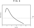
- the distance D xs from the X-ray generation portion XG to the inspection plane IP is desirably made small.
- Fig. 6 shows a result of obtaining, by an experiment, the relationship between the distance D xs (abscissa) and the count (ordinate) of foreign substances FS detected by the X-ray detector 120.
- the count is a total count (peak count), per predetermined time, of energy corresponding to the position of fluorescent X-rays (for example, Ni K ⁇ -rays) exiting from a specific element contained in the foreign substance.
- the distance D xs from the X-ray generation portion XG to the inspection plane IP is desirably 5 mm or less, more desirably 4 mm or less, and still more desirably 3 mm or less.
- the X-ray generation tube 101 for example, a sealed transmission microfocus X-ray source of Canon ANELVA, more specifically, the G series, and still more specifically, the G-511 series or G-311 series is useful.
- a distance D sf from the inspection plane IP to the X-ray detection panel 130 needs to be made sufficiently larger than D xs .
- D sf a distance from the inspection plane IP to the X-ray detection panel 130
- D xs a distance from the inspection plane IP to the X-ray detection panel 130
- D sf /D xs is set to desirably 20 or more, and more desirably 200 or more. This can detect a foreign substance with high sensitivity using a transmission image.
- the inspection apparatus IA is useful to detect a foreign substance attached to a material of a lithium ion battery in a manufacturing step of the lithium ion battery, but is merely an example and is also useful for other application purposes.
- the inspection apparatus IA may be used to measure and analyze airborne particles such as PM2.5 influencing the environment and health.
- airborne particles such as PM2.5 influencing the environment and health.
- the inspection apparatus IA for the conventional technique of periodically (for example, every hour or every day) measuring the number of particles and the sizes of the particles, it is possible to simultaneously specify materials or elements forming the particles in addition to measurement of the number of particles and the sizes of the particles, thereby implementing more advanced environmental and health measures.
- the inspection apparatus IA for the field of semiconductors, micronization of which has recently been advanced, such as an "EUV mask manufacturing apparatus, an inspection apparatus, and an inspection apparatus of a semiconductor manufacturing step, it is possible to improve a yield and early solve the cause of an abnormality using the element information of a foreign substance.
- the inspection method can include an X-ray detection step of emitting X-rays to the inspection plane IP (inspection target surface TS) and detecting, by the X-ray detector 120, the X-rays XF emitted from the foreign substance FS existing on the inspection target surface TS and totally reflected by the inspection target surface TS, and a processing step of processing an output of the X-ray detector 120.
- the processing step can include a step of detecting the foreign substance FS and/or a step of specifying a material forming the foreign substance FS.
- the inspection method can further include a step of detecting, by the X-ray detection panel 130, X-rays transmitted through the inspection target object IT having the inspection target surface TS, and in the processing step, the output of the X-ray detector 120 and an output of the X-ray detection panel 130 can be processed.
- the processing step can include a step of detecting the existence of the foreign substance FS and the position of the foreign substance FS based on the output of the X-ray detection panel 130.
- the processing step can include a step of detecting the existence of the foreign substance FS, the position of the foreign substance FS, and the size of the foreign substance FS based on the output of the X-ray detection panel 130.
- the inspection apparatus having the function of specifying a material forming a foreign substance has been explained.
- the inspection apparatus need not have the function of specifying a material forming a foreign substance.
- a limited amount of X-rays emitted from a foreign substance and totally reflected can be detected. Therefore, sufficient foreign substance specifying accuracy cannot be obtained, and a foreign substance on the inspection target object is missed, thereby lowering the manufacturing yield.
- an inexpensive inspection apparatus by eliminating a function of specifying the position of a foreign substance by an image of X-rays transmitted through an inspection target object. Furthermore, if the function of specifying a material forming a foreign substance is unnecessary, it is possible to use an inexpensive X-ray detector (for example, a proportional counter or NaI scintillator) having a low energy resolution of 1 keV or more (a coarse resolution with a large half-value width of given intensity). In addition, an inexpensive X-ray detector that has a high energy resolution of about several eV but has no energy analysis function, represented by PIN and CCD photodiodes, can be used.
- an inexpensive X-ray detector for example, a proportional counter or NaI scintillator having a low energy resolution of 1 keV or more (a coarse resolution with a large half-value width of given intensity).
- an inexpensive X-ray detector that has a high energy resolution of about several eV but has no energy analysis function, represented by PIN and CCD photod
- the X-ray detector 120 can be an X-ray detector that detects X-rays having energy within a range of 50 eV to 50 keV
- a plurality of detectors may be provided. By providing a plurality of detectors, it is possible to improve accuracy of detecting X-rays emitted from a foreign substance and totally reflected.
- Fig. 8 schematically shows the arrangement of an inspection apparatus IA according to the second embodiment. Matters not mentioned in the second embodiment can comply with the first embodiment.
- the inspection apparatus IA according to the second embodiment can include a plurality of X-ray detectors, for example, a first X-ray detector 1201 and a second X-ray detector 1202.
- the first X-ray detector 1201 and the second X-ray detector 1202 can be arranged to face each other via an axis AX of an X-ray generation tube 101. From another viewpoint, the first X-ray detector 1201 and the second X-ray detector 1202 can be arranged to face each other.
- Each of the first X-ray detector 1201 and the second X-ray detector 1202 can be formed by an inexpensive X-ray detector such as a PIN photodiode.
- the inspection apparatus IA according to the second embodiment can include slit members 1251 and 1252 similar to the slit member 125 in the inspection apparatus IA of the first embodiment.
- the slit members 1251 and 1252 can be provided for the first X-ray detector 1201 and the second X-ray detector 1202, respectively.
- a foreign substance FS1 irradiated with X-rays XR from an X-ray generation portion XG emits X-rays radially (for example, in all directions of 360°), and some of the X-rays can totally be reflected by an inspection target surface TS.
- the X-rays totally reflected by the inspection target surface TS include, for example, X-rays XF11 entering the first X-ray detector 1201 and X-rays XF12 entering the second X-ray detector 1202.
- the X-rays XF11 and XF12 shown in Fig. 8 can be understood as trajectory vectors of X-ray photons.
- Another foreign substance can exist on the inspection target surface TS in addition to the foreign substance FS1.
- the X-rays emitted from the foreign substance FS1 and totally reflected by the inspection target surface TS may be blocked by the other foreign substance and may not enter one of the plurality of X-ray detectors.
- the possibility that one of the plurality of X-ray detectors can detect the X-rays emitted from the foreign substance FS1 and totally reflected by the inspection target surface TS becomes higher.
- Fig. 9 schematically shows the arrangement of an inspection apparatus IA according to the third embodiment.
- Fig. 9 is a view of the inspection apparatus IA when viewed from an oblique direction. Matters not mentioned in the third embodiment can comply with the first or second embodiment.
- Fig. 9 does not illustrate a slit member but a slit member may be provided, similar to the second embodiment.
- the inspection apparatus IA can include a conveyance mechanism CV that conveys an inspection target object IT along a conveyance direction DIR.
- a first X-ray detector 1201 and a second X-ray detector 1202 can be arranged at positions apart from each other in a direction parallel to the conveyance direction DIR or a direction parallel to the longitudinal direction of the inspection target object IT.
- Fig. 9 shows X-rays XF11 (a trajectory vector of X-ray photons) and X-rays XF12 (a trajectory vector of X-ray photons) emitted from a foreign substance FS1 irradiated with X-rays XR from an X-ray generation portion XG and totally reflected by an inspection target surface TS.
- the X-rays XF11 enter the first X-ray detector 1201 and the X-rays XF12 enter the second X-ray detector 1202.
- a foreign substance FS2 different from the foreign substance FS1 can exist on the inspection target surface TS.
- the foreign substance FS2 exists between the foreign substance FS1 and the first X-ray detector 1201. If the X-rays XF11 are blocked by the foreign substance FS2, the first X-ray detector 1201 cannot detect the X-rays XF11. However, the second X-ray detector 1202 can detect the X-rays XF12 from the foreign substance FS1. This can reduce the possibility that the foreign substance on the inspection target surface TS of the inspection target object IT is missed, thereby preventing the manufacturing yield from lowering.
- the position of the foreign substance can be estimated. For example, in the example shown in Fig. 9 , it can be estimated that the foreign substance FS2 exists between the foreign substance FS1 and the second X-ray detector 1202.
- the inspection apparatus IA may include an additional X-ray detector that is arranged to detect X-rays totally reflected by a foreign substance existing on a surface on the opposite side of the inspection target surface TS.
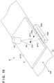
- Fig. 10 schematically shows the arrangement of an inspection apparatus IA according to the fourth embodiment. Matters not mentioned in the fourth embodiment can comply with the first to third embodiments.
- Fig. 10 shows X-rays XF11 and XF12 emitted from a foreign substance FS1 and totally reflected by an inspection target surface TS.
- the inspection apparatus IA according to the fourth embodiment can include an X-ray detector 1205 including a long X-ray receiving portion 1206 that extends in a predetermined direction.
- the X-ray detector 1205 can be formed by an inexpensive X-ray detector such as a PIN photodiode.
- Fig. 10 schematically shows the arrangement of an inspection apparatus IA according to the fourth embodiment. Matters not mentioned in the fourth embodiment can comply with the first to third embodiments.
- Fig. 10 shows X-rays XF11 and XF12 emitted from a foreign substance FS1 and totally reflected by an inspection target surface TS.
- the X-ray receiving portion1206 extends in a direction parallel to a surface parallel to the inspection target surface TS. From another viewpoint, the X-ray receiving portion 1206 extends in a direction parallel to the longitudinal direction of the inspection target object IT. From still another viewpoint, the X-ray receiving portion1206 extends in a direction parallel to a conveyance direction DIR.
- the X-ray receiving portion 1206 can have a rectangular shape having short and long sides, and the longitudinal direction is a direction parallel to the long side.
- the long side can have, for example, a length which is three or more times longer than the short side.
- the inspection apparatus IA may include a slit member having a slit, and the slit member can have a rectangular shape that extends along the longitudinal direction of the X-ray receiving portion 1206.
- the slit may be divided into a plurality of partial slits and then arranged.
- the slit member is advantageous in improving the detection accuracy of a foreign substance. Furthermore, by providing the slit member, it is possible to specify the position of a foreign substance based on the positional relationship between the X-ray receiving portion 1206 and the slit.
- the long X-ray receiving portion 1206 is advantageous in detecting the foreign substance FS1 even in a case where some of the X-rays emitted from the foreign substance FS1 and totally reflected by the inspection target surface TS are blocked by another foreign substance FS2.
- the X-rays XF11 emitted from the foreign substance FS1 and totally reflected by the inspection target surface TS can be blocked by the foreign substance FS2 but the X-rays XF12 emitted from the foreign substance FS1 and totally reflected by the inspection target surface TS can enter the X-ray receiving portion 1206.
- the inspection apparatus IA may include two or more X-ray detectors 1205.
- the two or more X-ray detectors 1205 can be arranged so that the longitudinal directions coincide with directions parallel to the conveyance direction DIR. In addition, the two or more X-ray detectors 1205 can be arranged to overlap each other in a direction orthogonal to the conveyance direction DIR.
- the inspection apparatus IA may further include an X-ray detector including an X-ray receiving portion with a longitudinal direction extending along a direction intersecting the conveyance direction DIR, for example, a direction orthogonal to the conveyance direction DIR.
Landscapes
- Chemical & Material Sciences (AREA)
- Health & Medical Sciences (AREA)
- Physics & Mathematics (AREA)
- Biochemistry (AREA)
- Life Sciences & Earth Sciences (AREA)
- Analytical Chemistry (AREA)
- General Health & Medical Sciences (AREA)
- General Physics & Mathematics (AREA)
- Immunology (AREA)
- Pathology (AREA)
- Crystallography & Structural Chemistry (AREA)
- Toxicology (AREA)
- High Energy & Nuclear Physics (AREA)
- General Engineering & Computer Science (AREA)
- Engineering & Computer Science (AREA)
- Analysing Materials By The Use Of Radiation (AREA)
Applications Claiming Priority (2)
| Application Number | Priority Date | Filing Date | Title |
|---|---|---|---|
| JP2022013653 | 2022-01-31 | ||
| PCT/JP2022/043908 WO2023145238A1 (fr) | 2022-01-31 | 2022-11-29 | Dispositif d'inspection et procédé d'inspection |
Publications (2)
| Publication Number | Publication Date |
|---|---|
| EP4474804A1 true EP4474804A1 (fr) | 2024-12-11 |
| EP4474804A4 EP4474804A4 (fr) | 2026-01-21 |
Family
ID=87471017
Family Applications (5)
| Application Number | Title | Priority Date | Filing Date |
|---|---|---|---|
| EP22923964.5A Pending EP4474800A4 (fr) | 2022-01-31 | 2022-03-31 | Dispositif d'inspection et procédé d'inspection |
| EP22924089.0A Pending EP4474803A4 (fr) | 2022-01-31 | 2022-11-29 | Dispositif d'inspection et procédé d'inspection |
| EP22924088.2A Pending EP4474802A4 (fr) | 2022-01-31 | 2022-11-29 | Dispositif d'identification qui détecte une matière étrangère et fonctionne à l'aide de rayons x de fluorescence |
| EP22924087.4A Pending EP4474801A4 (fr) | 2022-01-31 | 2022-11-29 | Dispositif d'inspection et procédé d'inspection |
| EP22924090.8A Pending EP4474804A4 (fr) | 2022-01-31 | 2022-11-29 | Dispositif d'inspection et procédé d'inspection |
Family Applications Before (4)
| Application Number | Title | Priority Date | Filing Date |
|---|---|---|---|
| EP22923964.5A Pending EP4474800A4 (fr) | 2022-01-31 | 2022-03-31 | Dispositif d'inspection et procédé d'inspection |
| EP22924089.0A Pending EP4474803A4 (fr) | 2022-01-31 | 2022-11-29 | Dispositif d'inspection et procédé d'inspection |
| EP22924088.2A Pending EP4474802A4 (fr) | 2022-01-31 | 2022-11-29 | Dispositif d'identification qui détecte une matière étrangère et fonctionne à l'aide de rayons x de fluorescence |
| EP22924087.4A Pending EP4474801A4 (fr) | 2022-01-31 | 2022-11-29 | Dispositif d'inspection et procédé d'inspection |
Country Status (7)
| Country | Link |
|---|---|
| US (6) | US11921059B2 (fr) |
| EP (5) | EP4474800A4 (fr) |
| JP (6) | JP7667882B2 (fr) |
| KR (5) | KR20240141192A (fr) |
| CN (5) | CN118661094A (fr) |
| TW (6) | TW202433050A (fr) |
| WO (5) | WO2023145101A1 (fr) |
Families Citing this family (1)
| Publication number | Priority date | Publication date | Assignee | Title |
|---|---|---|---|---|
| WO2023145101A1 (fr) * | 2022-01-31 | 2023-08-03 | キヤノンアネルバ株式会社 | Dispositif d'inspection et procédé d'inspection |
Family Cites Families (55)
| Publication number | Priority date | Publication date | Assignee | Title |
|---|---|---|---|---|
| JPH01244344A (ja) * | 1988-03-25 | 1989-09-28 | Hitachi Ltd | X線吸収スペクトル測定装置 |
| JPH07119717B2 (ja) * | 1989-12-12 | 1995-12-20 | シャープ株式会社 | 半導体材料評価装置 |
| JPH0534131A (ja) * | 1991-08-05 | 1993-02-09 | Fujitsu Ltd | 画像処理方法及び画像処理装置 |
| JPH05346411A (ja) * | 1992-04-16 | 1993-12-27 | Rigaku Denki Kogyo Kk | 蛍光x線分析装置 |
| EP0697109B1 (fr) * | 1994-03-02 | 1999-07-14 | Koninklijke Philips Electronics N.V. | Spectrometre a rayons x presentant un angle de capture rasant |
| JP3165615B2 (ja) * | 1995-03-17 | 2001-05-14 | 財団法人国際超電導産業技術研究センター | 表面元素分析方法及び装置 |
| KR100233312B1 (ko) | 1995-08-09 | 1999-12-01 | 야마모토 카즈모토 | 전반사 형광 x선 분석 장치 및 방법 |
| US5742658A (en) * | 1996-05-23 | 1998-04-21 | Advanced Micro Devices, Inc. | Apparatus and method for determining the elemental compositions and relative locations of particles on the surface of a semiconductor wafer |
| JPH09318565A (ja) * | 1996-05-24 | 1997-12-12 | Rigaku Ind Co | X線分析方法および装置 |
| JP2984232B2 (ja) * | 1996-10-25 | 1999-11-29 | 株式会社テクノス研究所 | X線分析装置およびx線照射角設定方法 |
| US6005915A (en) | 1997-11-07 | 1999-12-21 | Advanced Micro Devices, Inc. | Apparatus and method for measuring the roughness of a target material surface based upon the scattering of incident X-ray photons |
| US6108398A (en) | 1998-07-13 | 2000-08-22 | Jordan Valley Applied Radiation Ltd. | X-ray microfluorescence analyzer |
| JP2000055841A (ja) * | 1998-08-13 | 2000-02-25 | Fujitsu Ltd | X線分析方法 |
| DE19934987B4 (de) | 1999-07-26 | 2004-11-11 | Fraunhofer-Gesellschaft zur Förderung der angewandten Forschung e.V. | Röntgenanode und ihre Verwendung |
| DE19948382A1 (de) * | 1999-10-07 | 2001-05-03 | Gemetec Ges Fuer Mestechnik Un | Detektor für grosse Waferflächen |
| JP2001208708A (ja) | 2000-01-31 | 2001-08-03 | Japan Science & Technology Corp | 斜出射電子線プローブマイクロx線分析による異物の分析方法およびその装置 |
| US6829327B1 (en) * | 2000-09-22 | 2004-12-07 | X-Ray Optical Systems, Inc. | Total-reflection x-ray fluorescence apparatus and method using a doubly-curved optic |
| JP2002202272A (ja) | 2000-12-28 | 2002-07-19 | Shimadzu Corp | X線透視検査装置 |
| JP3673825B2 (ja) | 2001-03-27 | 2005-07-20 | 独立行政法人物質・材料研究機構 | 斜出射x線分析方法 |
| JP3998556B2 (ja) * | 2002-10-17 | 2007-10-31 | 株式会社東研 | 高分解能x線顕微検査装置 |
| US7065176B2 (en) | 2003-05-28 | 2006-06-20 | General Electric Company | Method and system to inspect a component |
| JP2005121468A (ja) * | 2003-10-16 | 2005-05-12 | Tohken Co Ltd | 蛍光x線を利用した毛髪等の食品異物検査装置 |
| JP2005292077A (ja) * | 2004-04-05 | 2005-10-20 | Fuji Electric Holdings Co Ltd | X線顕微鏡装置 |
| US7916834B2 (en) | 2007-02-12 | 2011-03-29 | Thermo Niton Analyzers Llc | Small spot X-ray fluorescence (XRF) analyzer |
| JP2007212468A (ja) * | 2007-03-16 | 2007-08-23 | Tohken Co Ltd | 高分解機能x線顕微検査装置 |
| JP5127313B2 (ja) | 2007-06-15 | 2013-01-23 | 義久 石黒 | 検査システム |
| JP2009075018A (ja) * | 2007-09-21 | 2009-04-09 | Technos:Kk | 蛍光x線分析装置および蛍光x線分析方法 |
| JP5489412B2 (ja) | 2008-03-26 | 2014-05-14 | 株式会社マーストーケンソリューション | 蛍光x線分析機能付き高分解能x線顕微装置 |
| JP5292323B2 (ja) | 2010-01-25 | 2013-09-18 | 株式会社リガク | 微小部x線計測装置 |
| JP4914514B2 (ja) | 2010-07-02 | 2012-04-11 | 株式会社リガク | 蛍光x線分析装置および方法 |
| JP5887760B2 (ja) * | 2011-08-24 | 2016-03-16 | 富士通株式会社 | 半導体装置の検査方法及び半導体装置の製造方法 |
| JP5881159B2 (ja) | 2012-03-27 | 2016-03-09 | 株式会社リガク | 異種物質の検査装置及び異種物質の検査方法 |
| US9194828B2 (en) * | 2012-05-22 | 2015-11-24 | Aribex, Inc. | Handheld x-ray system for 3D scatter imaging |
| US20140067316A1 (en) * | 2012-08-30 | 2014-03-06 | Kabushiki Kaisha Toshiba | Measuring apparatus, detector deviation monitoring method and measuring method |
| JP6026936B2 (ja) | 2013-03-28 | 2016-11-16 | 株式会社日立ハイテクサイエンス | 異物検出装置 |
| US9551677B2 (en) * | 2014-01-21 | 2017-01-24 | Bruker Jv Israel Ltd. | Angle calibration for grazing-incidence X-ray fluorescence (GIXRF) |
| US9594036B2 (en) * | 2014-02-28 | 2017-03-14 | Sigray, Inc. | X-ray surface analysis and measurement apparatus |
| EP2927948A1 (fr) | 2014-04-04 | 2015-10-07 | Nordson Corporation | Appareil d'inspection aux rayons X pour plaquettes semi-conductrices |
| CN107076684B (zh) | 2014-09-02 | 2021-04-02 | 株式会社尼康 | 测量处理装置、测量处理方法和测量处理程序 |
| WO2016059673A1 (fr) * | 2014-10-14 | 2016-04-21 | 株式会社リガク | Dispositif d'inspection de film mince à rayons x |
| DE112015006104B4 (de) * | 2015-03-25 | 2022-05-19 | Hitachi High-Tech Corporation | Elektronenmikroskop |
| WO2017003665A1 (fr) * | 2015-06-30 | 2017-01-05 | Illinois Tool Works Inc. | Appareil et procédé de mesure à rayons x en ligne |
| US10295486B2 (en) * | 2015-08-18 | 2019-05-21 | Sigray, Inc. | Detector for X-rays with high spatial and high spectral resolution |
| WO2017104659A1 (fr) * | 2015-12-15 | 2017-06-22 | 株式会社堀場製作所 | Tube à rayons x et spectromètre à rayons x |
| CN105758345B (zh) * | 2016-04-22 | 2018-06-05 | 武汉科技大学 | 一种在线测量带钢镀层厚度的x射线荧光成像装置 |
| CN206020314U (zh) * | 2016-09-09 | 2017-03-15 | 广州市怡文环境科技股份有限公司 | 一种全反射x射线荧光分析系统 |
| JP6867224B2 (ja) * | 2017-04-28 | 2021-04-28 | 浜松ホトニクス株式会社 | X線管及びx線発生装置 |
| US10895541B2 (en) | 2018-01-06 | 2021-01-19 | Kla-Tencor Corporation | Systems and methods for combined x-ray reflectometry and photoelectron spectroscopy |
| JP2019215205A (ja) | 2018-06-12 | 2019-12-19 | ローム株式会社 | 撮像装置、撮像方法、及び検査装置 |
| JP6601854B1 (ja) * | 2018-06-21 | 2019-11-06 | 株式会社リガク | 蛍光x線分析システム |
| JP7153525B2 (ja) * | 2018-10-12 | 2022-10-14 | アンリツ株式会社 | X線検査装置 |
| JP7270637B2 (ja) | 2018-10-25 | 2023-05-10 | 株式会社堀場製作所 | X線分析装置及びx線発生ユニット |
| CN113877059B (zh) | 2020-07-03 | 2025-12-09 | 何浩明 | 具有调整机构以使贴片单元贴合人体的衣物结构 |
| CN114486971A (zh) | 2022-01-25 | 2022-05-13 | 深圳市埃芯半导体科技有限公司 | 多源设计的x射线分析系统和方法 |
| WO2023145101A1 (fr) * | 2022-01-31 | 2023-08-03 | キヤノンアネルバ株式会社 | Dispositif d'inspection et procédé d'inspection |
-
2022
- 2022-03-31 WO PCT/JP2022/016709 patent/WO2023145101A1/fr not_active Ceased
- 2022-03-31 EP EP22923964.5A patent/EP4474800A4/fr active Pending
- 2022-03-31 CN CN202280090523.2A patent/CN118661094A/zh active Pending
- 2022-03-31 KR KR1020247028367A patent/KR20240141192A/ko active Pending
- 2022-11-29 CN CN202280090513.9A patent/CN118891514A/zh not_active Withdrawn
- 2022-11-29 JP JP2023576658A patent/JP7667882B2/ja active Active
- 2022-11-29 JP JP2023576656A patent/JP7667321B2/ja active Active
- 2022-11-29 EP EP22924089.0A patent/EP4474803A4/fr active Pending
- 2022-11-29 WO PCT/JP2022/043908 patent/WO2023145238A1/fr not_active Ceased
- 2022-11-29 EP EP22924088.2A patent/EP4474802A4/fr active Pending
- 2022-11-29 CN CN202280090524.7A patent/CN118679379A/zh not_active Withdrawn
- 2022-11-29 KR KR1020247028350A patent/KR20240141191A/ko not_active Withdrawn
- 2022-11-29 WO PCT/JP2022/043906 patent/WO2023145236A1/fr not_active Ceased
- 2022-11-29 JP JP2023576659A patent/JP7667883B2/ja active Active
- 2022-11-29 KR KR1020247027476A patent/KR20240136405A/ko not_active Withdrawn
- 2022-11-29 EP EP22924087.4A patent/EP4474801A4/fr active Pending
- 2022-11-29 JP JP2023576657A patent/JP7667322B2/ja active Active
- 2022-11-29 KR KR1020247027603A patent/KR20240136411A/ko not_active Withdrawn
- 2022-11-29 WO PCT/JP2022/043905 patent/WO2023145235A1/fr not_active Ceased
- 2022-11-29 CN CN202280090521.3A patent/CN118661093A/zh not_active Withdrawn
- 2022-11-29 KR KR1020247028368A patent/KR20240135667A/ko active Pending
- 2022-11-29 EP EP22924090.8A patent/EP4474804A4/fr active Pending
- 2022-11-29 CN CN202280090522.8A patent/CN118901003A/zh active Pending
- 2022-11-29 WO PCT/JP2022/043907 patent/WO2023145237A1/fr not_active Ceased
-
2023
- 2023-01-06 JP JP2023001301A patent/JP7615183B2/ja active Active
- 2023-01-19 TW TW113116471A patent/TW202433050A/zh unknown
- 2023-01-19 TW TW112102600A patent/TWI846289B/zh active
- 2023-01-30 TW TW112103027A patent/TWI866041B/zh active
- 2023-01-30 TW TW112103028A patent/TWI845135B/zh active
- 2023-01-30 TW TW112103029A patent/TWI874900B/zh active
- 2023-01-30 TW TW112103030A patent/TWI845136B/zh active
- 2023-07-11 US US18/350,093 patent/US11921059B2/en active Active
- 2023-07-11 US US18/350,361 patent/US12241848B2/en active Active
- 2023-07-11 US US18/350,054 patent/US11927554B2/en active Active
- 2023-07-11 US US18/350,255 patent/US11971370B2/en active Active
- 2023-07-11 US US18/350,221 patent/US11977038B2/en active Active
-
2024
- 2024-07-18 US US18/776,818 patent/US20240369502A1/en active Pending
- 2024-12-26 JP JP2024230910A patent/JP2025039599A/ja active Pending
Also Published As
Similar Documents
| Publication | Publication Date | Title |
|---|---|---|
| US7627088B2 (en) | X-ray tube and X-ray analysis apparatus | |
| US20240369502A1 (en) | Inspection apparatus and inspection method |
Legal Events
| Date | Code | Title | Description |
|---|---|---|---|
| STAA | Information on the status of an ep patent application or granted ep patent |
Free format text: STATUS: THE INTERNATIONAL PUBLICATION HAS BEEN MADE |
|
| PUAI | Public reference made under article 153(3) epc to a published international application that has entered the european phase |
Free format text: ORIGINAL CODE: 0009012 |
|
| STAA | Information on the status of an ep patent application or granted ep patent |
Free format text: STATUS: REQUEST FOR EXAMINATION WAS MADE |
|
| 17P | Request for examination filed |
Effective date: 20240326 |
|
| AK | Designated contracting states |
Kind code of ref document: A1 Designated state(s): AL AT BE BG CH CY CZ DE DK EE ES FI FR GB GR HR HU IE IS IT LI LT LU LV MC ME MK MT NL NO PL PT RO RS SE SI SK SM TR |
|
| DAV | Request for validation of the european patent (deleted) | ||
| DAX | Request for extension of the european patent (deleted) | ||
| A4 | Supplementary search report drawn up and despatched |
Effective date: 20251223 |
|
| RIC1 | Information provided on ipc code assigned before grant |
Ipc: G01N 23/223 20060101AFI20251217BHEP Ipc: G01N 23/04 20180101ALI20251217BHEP Ipc: G01N 23/2206 20180101ALI20251217BHEP |