EP4488131A2 - Betätigungseinrichtung für ein ganz oder teilweise hydraulisch wirkendes bremssystem für ein fahrzeug - Google Patents
Betätigungseinrichtung für ein ganz oder teilweise hydraulisch wirkendes bremssystem für ein fahrzeug Download PDFInfo
- Publication number
- EP4488131A2 EP4488131A2 EP24209116.3A EP24209116A EP4488131A2 EP 4488131 A2 EP4488131 A2 EP 4488131A2 EP 24209116 A EP24209116 A EP 24209116A EP 4488131 A2 EP4488131 A2 EP 4488131A2
- Authority
- EP
- European Patent Office
- Prior art keywords
- brake
- pressure
- pressure supply
- valve
- ecu
- Prior art date
- Legal status (The legal status is an assumption and is not a legal conclusion. Google has not performed a legal analysis and makes no representation as to the accuracy of the status listed.)
- Granted
Links
Images





Classifications
-
- B—PERFORMING OPERATIONS; TRANSPORTING
- B60—VEHICLES IN GENERAL
- B60T—VEHICLE BRAKE CONTROL SYSTEMS OR PARTS THEREOF; BRAKE CONTROL SYSTEMS OR PARTS THEREOF, IN GENERAL; ARRANGEMENT OF BRAKING ELEMENTS ON VEHICLES IN GENERAL; PORTABLE DEVICES FOR PREVENTING UNWANTED MOVEMENT OF VEHICLES; VEHICLE MODIFICATIONS TO FACILITATE COOLING OF BRAKES
- B60T13/00—Transmitting braking action from initiating means to ultimate brake actuator with power assistance or drive; Brake systems incorporating such transmitting means, e.g. air-pressure brake systems
- B60T13/10—Transmitting braking action from initiating means to ultimate brake actuator with power assistance or drive; Brake systems incorporating such transmitting means, e.g. air-pressure brake systems with fluid assistance, drive, or release
- B60T13/12—Transmitting braking action from initiating means to ultimate brake actuator with power assistance or drive; Brake systems incorporating such transmitting means, e.g. air-pressure brake systems with fluid assistance, drive, or release the fluid being liquid
- B60T13/14—Transmitting braking action from initiating means to ultimate brake actuator with power assistance or drive; Brake systems incorporating such transmitting means, e.g. air-pressure brake systems with fluid assistance, drive, or release the fluid being liquid using accumulators or reservoirs fed by pumps
- B60T13/142—Systems with master cylinder
-
- B—PERFORMING OPERATIONS; TRANSPORTING
- B60—VEHICLES IN GENERAL
- B60T—VEHICLE BRAKE CONTROL SYSTEMS OR PARTS THEREOF; BRAKE CONTROL SYSTEMS OR PARTS THEREOF, IN GENERAL; ARRANGEMENT OF BRAKING ELEMENTS ON VEHICLES IN GENERAL; PORTABLE DEVICES FOR PREVENTING UNWANTED MOVEMENT OF VEHICLES; VEHICLE MODIFICATIONS TO FACILITATE COOLING OF BRAKES
- B60T13/00—Transmitting braking action from initiating means to ultimate brake actuator with power assistance or drive; Brake systems incorporating such transmitting means, e.g. air-pressure brake systems
- B60T13/10—Transmitting braking action from initiating means to ultimate brake actuator with power assistance or drive; Brake systems incorporating such transmitting means, e.g. air-pressure brake systems with fluid assistance, drive, or release
- B60T13/12—Transmitting braking action from initiating means to ultimate brake actuator with power assistance or drive; Brake systems incorporating such transmitting means, e.g. air-pressure brake systems with fluid assistance, drive, or release the fluid being liquid
- B60T13/14—Transmitting braking action from initiating means to ultimate brake actuator with power assistance or drive; Brake systems incorporating such transmitting means, e.g. air-pressure brake systems with fluid assistance, drive, or release the fluid being liquid using accumulators or reservoirs fed by pumps
- B60T13/148—Arrangements for pressure supply
-
- B—PERFORMING OPERATIONS; TRANSPORTING
- B60—VEHICLES IN GENERAL
- B60T—VEHICLE BRAKE CONTROL SYSTEMS OR PARTS THEREOF; BRAKE CONTROL SYSTEMS OR PARTS THEREOF, IN GENERAL; ARRANGEMENT OF BRAKING ELEMENTS ON VEHICLES IN GENERAL; PORTABLE DEVICES FOR PREVENTING UNWANTED MOVEMENT OF VEHICLES; VEHICLE MODIFICATIONS TO FACILITATE COOLING OF BRAKES
- B60T13/00—Transmitting braking action from initiating means to ultimate brake actuator with power assistance or drive; Brake systems incorporating such transmitting means, e.g. air-pressure brake systems
- B60T13/10—Transmitting braking action from initiating means to ultimate brake actuator with power assistance or drive; Brake systems incorporating such transmitting means, e.g. air-pressure brake systems with fluid assistance, drive, or release
- B60T13/12—Transmitting braking action from initiating means to ultimate brake actuator with power assistance or drive; Brake systems incorporating such transmitting means, e.g. air-pressure brake systems with fluid assistance, drive, or release the fluid being liquid
- B60T13/16—Transmitting braking action from initiating means to ultimate brake actuator with power assistance or drive; Brake systems incorporating such transmitting means, e.g. air-pressure brake systems with fluid assistance, drive, or release the fluid being liquid using pumps directly, i.e. without interposition of accumulators or reservoirs
-
- B—PERFORMING OPERATIONS; TRANSPORTING
- B60—VEHICLES IN GENERAL
- B60T—VEHICLE BRAKE CONTROL SYSTEMS OR PARTS THEREOF; BRAKE CONTROL SYSTEMS OR PARTS THEREOF, IN GENERAL; ARRANGEMENT OF BRAKING ELEMENTS ON VEHICLES IN GENERAL; PORTABLE DEVICES FOR PREVENTING UNWANTED MOVEMENT OF VEHICLES; VEHICLE MODIFICATIONS TO FACILITATE COOLING OF BRAKES
- B60T13/00—Transmitting braking action from initiating means to ultimate brake actuator with power assistance or drive; Brake systems incorporating such transmitting means, e.g. air-pressure brake systems
- B60T13/10—Transmitting braking action from initiating means to ultimate brake actuator with power assistance or drive; Brake systems incorporating such transmitting means, e.g. air-pressure brake systems with fluid assistance, drive, or release
- B60T13/66—Electrical control in fluid-pressure brake systems
-
- B—PERFORMING OPERATIONS; TRANSPORTING
- B60—VEHICLES IN GENERAL
- B60T—VEHICLE BRAKE CONTROL SYSTEMS OR PARTS THEREOF; BRAKE CONTROL SYSTEMS OR PARTS THEREOF, IN GENERAL; ARRANGEMENT OF BRAKING ELEMENTS ON VEHICLES IN GENERAL; PORTABLE DEVICES FOR PREVENTING UNWANTED MOVEMENT OF VEHICLES; VEHICLE MODIFICATIONS TO FACILITATE COOLING OF BRAKES
- B60T13/00—Transmitting braking action from initiating means to ultimate brake actuator with power assistance or drive; Brake systems incorporating such transmitting means, e.g. air-pressure brake systems
- B60T13/10—Transmitting braking action from initiating means to ultimate brake actuator with power assistance or drive; Brake systems incorporating such transmitting means, e.g. air-pressure brake systems with fluid assistance, drive, or release
- B60T13/66—Electrical control in fluid-pressure brake systems
- B60T13/662—Electrical control in fluid-pressure brake systems characterised by specified functions of the control system components
-
- B—PERFORMING OPERATIONS; TRANSPORTING
- B60—VEHICLES IN GENERAL
- B60T—VEHICLE BRAKE CONTROL SYSTEMS OR PARTS THEREOF; BRAKE CONTROL SYSTEMS OR PARTS THEREOF, IN GENERAL; ARRANGEMENT OF BRAKING ELEMENTS ON VEHICLES IN GENERAL; PORTABLE DEVICES FOR PREVENTING UNWANTED MOVEMENT OF VEHICLES; VEHICLE MODIFICATIONS TO FACILITATE COOLING OF BRAKES
- B60T13/00—Transmitting braking action from initiating means to ultimate brake actuator with power assistance or drive; Brake systems incorporating such transmitting means, e.g. air-pressure brake systems
- B60T13/10—Transmitting braking action from initiating means to ultimate brake actuator with power assistance or drive; Brake systems incorporating such transmitting means, e.g. air-pressure brake systems with fluid assistance, drive, or release
- B60T13/66—Electrical control in fluid-pressure brake systems
- B60T13/68—Electrical control in fluid-pressure brake systems by electrically-controlled valves
-
- B—PERFORMING OPERATIONS; TRANSPORTING
- B60—VEHICLES IN GENERAL
- B60T—VEHICLE BRAKE CONTROL SYSTEMS OR PARTS THEREOF; BRAKE CONTROL SYSTEMS OR PARTS THEREOF, IN GENERAL; ARRANGEMENT OF BRAKING ELEMENTS ON VEHICLES IN GENERAL; PORTABLE DEVICES FOR PREVENTING UNWANTED MOVEMENT OF VEHICLES; VEHICLE MODIFICATIONS TO FACILITATE COOLING OF BRAKES
- B60T13/00—Transmitting braking action from initiating means to ultimate brake actuator with power assistance or drive; Brake systems incorporating such transmitting means, e.g. air-pressure brake systems
- B60T13/10—Transmitting braking action from initiating means to ultimate brake actuator with power assistance or drive; Brake systems incorporating such transmitting means, e.g. air-pressure brake systems with fluid assistance, drive, or release
- B60T13/66—Electrical control in fluid-pressure brake systems
- B60T13/68—Electrical control in fluid-pressure brake systems by electrically-controlled valves
- B60T13/686—Electrical control in fluid-pressure brake systems by electrically-controlled valves in hydraulic systems or parts thereof
-
- B—PERFORMING OPERATIONS; TRANSPORTING
- B60—VEHICLES IN GENERAL
- B60T—VEHICLE BRAKE CONTROL SYSTEMS OR PARTS THEREOF; BRAKE CONTROL SYSTEMS OR PARTS THEREOF, IN GENERAL; ARRANGEMENT OF BRAKING ELEMENTS ON VEHICLES IN GENERAL; PORTABLE DEVICES FOR PREVENTING UNWANTED MOVEMENT OF VEHICLES; VEHICLE MODIFICATIONS TO FACILITATE COOLING OF BRAKES
- B60T13/00—Transmitting braking action from initiating means to ultimate brake actuator with power assistance or drive; Brake systems incorporating such transmitting means, e.g. air-pressure brake systems
- B60T13/74—Transmitting braking action from initiating means to ultimate brake actuator with power assistance or drive; Brake systems incorporating such transmitting means, e.g. air-pressure brake systems with electrical assistance or drive
- B60T13/745—Transmitting braking action from initiating means to ultimate brake actuator with power assistance or drive; Brake systems incorporating such transmitting means, e.g. air-pressure brake systems with electrical assistance or drive acting on a hydraulic system, e.g. a master cylinder
-
- B—PERFORMING OPERATIONS; TRANSPORTING
- B60—VEHICLES IN GENERAL
- B60T—VEHICLE BRAKE CONTROL SYSTEMS OR PARTS THEREOF; BRAKE CONTROL SYSTEMS OR PARTS THEREOF, IN GENERAL; ARRANGEMENT OF BRAKING ELEMENTS ON VEHICLES IN GENERAL; PORTABLE DEVICES FOR PREVENTING UNWANTED MOVEMENT OF VEHICLES; VEHICLE MODIFICATIONS TO FACILITATE COOLING OF BRAKES
- B60T17/00—Component parts, details, or accessories of power brake systems not covered by groups B60T8/00, B60T13/00 or B60T15/00, or presenting other characteristic features
- B60T17/18—Safety devices; Monitoring
-
- B—PERFORMING OPERATIONS; TRANSPORTING
- B60—VEHICLES IN GENERAL
- B60T—VEHICLE BRAKE CONTROL SYSTEMS OR PARTS THEREOF; BRAKE CONTROL SYSTEMS OR PARTS THEREOF, IN GENERAL; ARRANGEMENT OF BRAKING ELEMENTS ON VEHICLES IN GENERAL; PORTABLE DEVICES FOR PREVENTING UNWANTED MOVEMENT OF VEHICLES; VEHICLE MODIFICATIONS TO FACILITATE COOLING OF BRAKES
- B60T7/00—Brake-action initiating means
- B60T7/02—Brake-action initiating means for personal initiation
- B60T7/04—Brake-action initiating means for personal initiation foot actuated
- B60T7/042—Brake-action initiating means for personal initiation foot actuated by electrical means, e.g. using travel or force sensors
-
- B—PERFORMING OPERATIONS; TRANSPORTING
- B60—VEHICLES IN GENERAL
- B60T—VEHICLE BRAKE CONTROL SYSTEMS OR PARTS THEREOF; BRAKE CONTROL SYSTEMS OR PARTS THEREOF, IN GENERAL; ARRANGEMENT OF BRAKING ELEMENTS ON VEHICLES IN GENERAL; PORTABLE DEVICES FOR PREVENTING UNWANTED MOVEMENT OF VEHICLES; VEHICLE MODIFICATIONS TO FACILITATE COOLING OF BRAKES
- B60T8/00—Arrangements for adjusting wheel-braking force to meet varying vehicular or ground-surface conditions, e.g. limiting or varying distribution of braking force
- B60T8/17—Using electrical or electronic regulation means to control braking
- B60T8/172—Determining control parameters used in the regulation, e.g. by calculations involving measured or detected parameters
-
- B—PERFORMING OPERATIONS; TRANSPORTING
- B60—VEHICLES IN GENERAL
- B60T—VEHICLE BRAKE CONTROL SYSTEMS OR PARTS THEREOF; BRAKE CONTROL SYSTEMS OR PARTS THEREOF, IN GENERAL; ARRANGEMENT OF BRAKING ELEMENTS ON VEHICLES IN GENERAL; PORTABLE DEVICES FOR PREVENTING UNWANTED MOVEMENT OF VEHICLES; VEHICLE MODIFICATIONS TO FACILITATE COOLING OF BRAKES
- B60T8/00—Arrangements for adjusting wheel-braking force to meet varying vehicular or ground-surface conditions, e.g. limiting or varying distribution of braking force
- B60T8/32—Arrangements for adjusting wheel-braking force to meet varying vehicular or ground-surface conditions, e.g. limiting or varying distribution of braking force responsive to a speed condition, e.g. acceleration or deceleration
-
- B—PERFORMING OPERATIONS; TRANSPORTING
- B60—VEHICLES IN GENERAL
- B60T—VEHICLE BRAKE CONTROL SYSTEMS OR PARTS THEREOF; BRAKE CONTROL SYSTEMS OR PARTS THEREOF, IN GENERAL; ARRANGEMENT OF BRAKING ELEMENTS ON VEHICLES IN GENERAL; PORTABLE DEVICES FOR PREVENTING UNWANTED MOVEMENT OF VEHICLES; VEHICLE MODIFICATIONS TO FACILITATE COOLING OF BRAKES
- B60T8/00—Arrangements for adjusting wheel-braking force to meet varying vehicular or ground-surface conditions, e.g. limiting or varying distribution of braking force
- B60T8/32—Arrangements for adjusting wheel-braking force to meet varying vehicular or ground-surface conditions, e.g. limiting or varying distribution of braking force responsive to a speed condition, e.g. acceleration or deceleration
- B60T8/34—Arrangements for adjusting wheel-braking force to meet varying vehicular or ground-surface conditions, e.g. limiting or varying distribution of braking force responsive to a speed condition, e.g. acceleration or deceleration having a fluid pressure regulator responsive to a speed condition
- B60T8/40—Arrangements for adjusting wheel-braking force to meet varying vehicular or ground-surface conditions, e.g. limiting or varying distribution of braking force responsive to a speed condition, e.g. acceleration or deceleration having a fluid pressure regulator responsive to a speed condition comprising an additional fluid circuit including fluid pressurising means for modifying the pressure of the braking fluid, e.g. including wheel driven pumps for detecting a speed condition, or pumps which are controlled by means independent of the braking system
- B60T8/4072—Systems in which a driver input signal is used as a control signal for the additional fluid circuit which is normally used for braking
- B60T8/4081—Systems with stroke simulating devices for driver input
-
- B—PERFORMING OPERATIONS; TRANSPORTING
- B60—VEHICLES IN GENERAL
- B60T—VEHICLE BRAKE CONTROL SYSTEMS OR PARTS THEREOF; BRAKE CONTROL SYSTEMS OR PARTS THEREOF, IN GENERAL; ARRANGEMENT OF BRAKING ELEMENTS ON VEHICLES IN GENERAL; PORTABLE DEVICES FOR PREVENTING UNWANTED MOVEMENT OF VEHICLES; VEHICLE MODIFICATIONS TO FACILITATE COOLING OF BRAKES
- B60T8/00—Arrangements for adjusting wheel-braking force to meet varying vehicular or ground-surface conditions, e.g. limiting or varying distribution of braking force
- B60T8/32—Arrangements for adjusting wheel-braking force to meet varying vehicular or ground-surface conditions, e.g. limiting or varying distribution of braking force responsive to a speed condition, e.g. acceleration or deceleration
- B60T8/34—Arrangements for adjusting wheel-braking force to meet varying vehicular or ground-surface conditions, e.g. limiting or varying distribution of braking force responsive to a speed condition, e.g. acceleration or deceleration having a fluid pressure regulator responsive to a speed condition
- B60T8/36—Arrangements for adjusting wheel-braking force to meet varying vehicular or ground-surface conditions, e.g. limiting or varying distribution of braking force responsive to a speed condition, e.g. acceleration or deceleration having a fluid pressure regulator responsive to a speed condition including a pilot valve responding to an electromagnetic force
- B60T8/3615—Electromagnetic valves specially adapted for anti-lock brake and traction control systems
- B60T8/3675—Electromagnetic valves specially adapted for anti-lock brake and traction control systems integrated in modulator units
- B60T8/368—Electromagnetic valves specially adapted for anti-lock brake and traction control systems integrated in modulator units combined with other mechanical components, e.g. pump units, master cylinders
Definitions
- the present invention relates to an actuating device for a fully or partially hydraulically acting brake system for a vehicle, with a master brake cylinder which has a piston-cylinder unit with a piston and a working chamber, wherein the working chamber is hydraulically connected or connectable to a reservoir and a pedal feel simulator and is mechanically connected via an actuating device, in particular a brake pedal, and the working chamber can be connected to at least one brake circuit via at least one normally open valve, and that at least one hydraulically acting wheel brake assigned to a brake circuit, each of which is assigned at least one separate controllable switching valve with which the wheel brake can be connected to the respective brake circuit for pressure build-up and pressure reduction, in particular in brake booster mode, and with a pressure supply driven by an electric motor, the piston of which can be adjusted in the cylinder by means of the electric motor, at least one valve arrangement with solenoid valves for wheel-specific pressure control, and at least one electrical control unit for controlling at least valves of the valve arrangement and the Motor of the pressure supply, as well as at least one controlled
- the focus here is on the pressure supply, where the braking force or pressure build-up must be guaranteed even without the driver's foot.
- the electronic control system must also be designed accordingly for this function.
- the ABS function must also be guaranteed even in the event of a fault.
- DE 10 2017 222 450 reveals a hydraulic system with only one master cylinder, redundant pressure supply, isolating valves to the master cylinder and a travel simulator.
- a bypass valve between the two brake circuits enables the second pressure supply to supply both brake circuits if one pressure supply fails.
- This normally open valve is extremely safety-relevant, as if the valve fails and the brake circuit fails, for example, this can result in total brake failure.
- the valve effort is very high.
- the DE 10 2017 222 435 and DE 10 2016 225 537 show a similar concept, but with an electric pedal, reduced pressure supply and bypass valve. All systems use a so-called outlet valve for the ABS function when the pressure is reduced. If a dirt particle gets into the valve seat when the valve is opened, this can cause a brake circuit failure during the next braking.
- DE 10 2017 207 954 shows a system concept with redundant pressure supply and without outlet valves for the ABS pressure control.
- the so-called multiplex process which is already used in DE 102005055751 and DE 102009008944 A1 described, in which the pressure control for ABS is carried out by the pressure supply through volume measurement and pressure information.
- the switching valves for pressure control are also used redundantly. A safety risk arises if the piston seal or a check valve to the reservoir fails and the switching valve is leaking due to dirt particles, which also results in a total failure of the brake.
- the packaging or construction volume of the braking system is also of great importance. Especially in systems with HAD (semi-automated) and FAD (fully automated driving), many variants from level 2 with tandem master cylinder (THZ) or single master cylinder (HZ) to level 5 without THZ or HZ must be taken into account in the design of the construction. In particular, 3 - 5 concepts with 2 pressure supplies or pressure supply devices (DV) are difficult to implement in the packaging with a small construction volume. Examples of packaging are from EP 2744691 with vertical arrangement of the pressure supply (DV) to the HZ axis and DE 2016032116160400 with parallel arrangement of the pressure supply device to the HZ axis, which require a smaller overall width.
- a simple master brake cylinder usually requires a braking system with several redundancies. This can be achieved if the master brake cylinder is designed with redundant and diagnosable seals, for example, and if further redundancies are provided in the pressure supply (e.g. pressure supply with 2x3 phase connection, red. on-board power supply connection) and in particular if other modules can be used for braking (e.g. electric parking brake, electric drive motor).
- the pressure supply e.g. pressure supply with 2x3 phase connection, red. on-board power supply connection
- other modules can be used for braking (e.g. electric parking brake, electric drive motor).
- the object of the present invention is to create a very cost-effective, short and narrow 1-box solution for automated driving of levels 2 to 3, which is also modular for other solutions based on it with later integration of a second pressure supply.
- a packaging with a small construction volume is proposed with an integrated pressure supply consisting of a pressure supply device, with valves, in particular solenoid valves combined in a hydraulic unit, with at least one electronic control and regulation unit, at least one reservoir, with a single master brake cylinder and pedal stroke sensors and travel simulator with pistons.
- the invention provides various variants of modularly constructed actuation systems for brake systems, which contain as many identical parts as possible for production and assembly.
- Housing A Includes the valve assembly (HCU) for the pressure supply device DV1 with e.g. valves (V), solenoid valves (MV) and one or more pressure sensors (DG).
- HCU valve assembly
- MV solenoid valves
- DG pressure sensors
- Housing B Includes the control and regulation unit ECU without redundancy with one main connector or with partial or full redundancy with two connectors to the vehicle electrical system.
- Housing C For HZ with pedal stroke sensors and small sensor ECU and reservoir VB for variant e.
- the HZ also includes the pedal interface (PI) to the brake pedal and also travel simulator with piston and spring.
- Housing A is preferably made from an extruded molded piece, which is very suitable for fastening and assembly using caulking technology.
- the DV1 with piston drive and KGT to the motor are to be integrated here, as well as the valves and solenoid valves.
- the interface to the control and regulation unit ECU is also similar to ABS/ESP.
- the master brake cylinder HZ with all the aforementioned components (housing C) can be screwed onto housing A - this applies to all variants except for variants e and f.
- housing C is mounted as an assembly separately from the unit on the bulkhead and the hydraulic line from the master brake cylinder HZ is connected to housing A.
- a
- the reservoir VB is located in housing A with two connections to the brake circuits or with an additional connection to the pressure supply DV.
- the float in the reservoir VB contains a target with a connection to the sensor element in the control and regulation unit ECU.
- the motor can preferably be connected to housing A via an intermediate housing, which is preferably made of plastic.
- the sensor required for the commutation of the motor and piston position can preferably be mounted on the motor axis on the side opposite the piston on the motor housing and connected to the control and regulation unit ECU.
- the sensor is located in an additional housing to the ECU.
- an additional small circuit board can be used in addition to the main circuit board PCB for a second connection of the solenoid coil.
- the packaging shown meets the requirements for modularity and small construction volume and is also very low in cost and weight.
- a special design of the reservoir allows its filler neck or opening to be advantageously positioned on or in front of the front of the housing of the electronic control unit or the actuating device so that it is easily accessible.
- the actual reservoir can be conveniently located behind the control unit, as the front filler neck is connected past the electronic control unit to the rear of the control unit housing.
- the side or middle area of the reservoir can advantageously be made narrow, so that the actuating device is not or only slightly wider than a conventional reservoir.
- Each wheel brake is assigned a switching valve. If no additional outlet valves are provided, the corresponding switching valve must be opened for a pressure change in the respective wheel brake, whereby the pressure supply device increases or reduces the pressure by moving its piston accordingly. As soon as the pressure in the wheel brake is regulated, the corresponding switching valve is closed again and a pressure change can be made in another wheel brake.
- At least one outlet valve for at least one wheel brake or brake circuit it is possible to provide a highly dynamic ESP and/or ABS function with just one pressure supply device, with the pressure being built up via the switching valves assigned to the wheel brakes. The pressure can then be released directly into the reservoir via the outlet valve assigned to a wheel brake when the switching valve of the wheel brake is closed, with a pressure change in another wheel brake or the other brake circuit being possible at the same time using the pressure supply device.
- Outlet valves should be installed particularly on hydraulic consumers with large volumes (e.g. on wheel brakes on the front axle) or at a central location between isolating valves that separate the brake circuits ( Fig. 5 ) are provided. Depending on the brake circuit design (diagonal or black-and-white), the outlet valves are arranged at different points in the hydraulic concept.
- the outlet valves In brake booster mode and in recuperation mode, pressure is built up and released via the pressure supply by the forward and backward movement of the piston, the outlet valves are operated closed.
- the multiplex method is primarily used according to DE 102005055751 and DE 102009008944 A1 used only in the case of extreme dynamic requirements, the outlet valve(s) is/are used to reduce the pressure, whereby the pressure reduction preferably takes place with the support of the signal from the pressure sensor.
- the brake circuit is only opened to the reservoir in very few cases, which has decisive advantages in terms of reliability.
- the switching valves are arranged in such a way that a pressure present in a wheel brake (RB) applies force to the valve actuator of the switching valve (SV) away from its valve seat.
- volume is supplied from the reservoir to the brake circuit when the pressure supply isolating valve is closed.
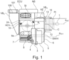
- Fig. 1 shows the side view of the integrated unit housing A with valve arrangement HCU, which contains the components MV, pressure sensor DG, piston for DV1 and fastening of the motor of DV1.
- the components such as valves, solenoid valve MV, pressure sensor DG are preferably fastened to a flow or extruded block 24, e.g. the MV preferably by caulking or clinching, which also includes its sealing.
- the piston 8 of the pressure supply unit DV1 is shown with return spring and housing cover 7, which is preferably driven by the spindle and ball screw drive KGT (not shown) via the motor 2.
- KGT spindle and ball screw drive
- the storage tank VB has a filler neck VB V with a filler opening 100 that can be closed by means of a cover 101 and that extends in front of the housing of the ECU, with a middle area VB M extending laterally on the housing of the ECU to the rear of the unit and opening into a rear area of the storage tank VB H , so that hydraulic medium can pass from the filler neck VB V into the rear area VBH.
- the sensor housing 3 with angle of rotation sensor is connected to both the motor 2 and the ECU 18 via a preferably flexible circuit board (not shown) with the intermediate housing.
- the plugs are attached to the top of the control and regulation unit ECU, which are designed twice in the redundant ECU.
- the corresponding connecting line to the master brake cylinder HZ is provided with 11.
- the reservoir VB can, as usual, contain a level sensor (NS) with a float, whereby the target with the sensor element is arranged in the control and regulation unit ECU, which is preferably designed redundantly at levels 4 and 5.
- the master brake cylinder HZ is arranged behind the valve arrangement block HCU and is screwed to the HCU block 24 with fastening screws 13.
- the motor sensor 34 for electronic commutation and control of the position of the piston.
- the motor can be equipped with various drive types, e.g. gear, trapezoid or spindle 57 with ball screw 58, as in Fig. 1a shown, combined.
- sensors can be used, such as segment sensors with inductive or magnetic field-sensitive sensors, or sensors that are arranged in the motor or transmission axis.
- These sensors are particularly simple in design and consist of a sensor target, e.g. in the form of a two- or multi-pole magnet, and a magnetic field-sensitive sensor element, e.g. in the form of a Hall sensor, GMR sensor, or similar.
- This sensor element 34 is electrically connected to the electronic control unit ECU, which is attached to the engine either directly or via an intermediate housing.
- the sensor element 34 is preferably in a sensor housing consisting of an outer housing part 52 and an inner housing part 52a and accommodates, among other things, a printed circuit board 22 on which the sensor element 34 can be arranged.
- an elastic part 61 is provided according to the invention.
- tolerances in all three directions x, y, z must be compensated.
- the sensor housing is advantageously divided into two parts, an outer housing 52 and an inner housing 52a, with the housing parts 52, 52a being connected to one another using conventional joining techniques such as welding or gluing and preferably made of plastic.
- the sensor housing is also fastened to the motor housing 62, preferably in two places.
- the sensor circuit board 22 is flexible in the upper part towards the connector strip in order to control the above-mentioned tolerances.
- a flex PCB flexible printed circuit board
- the electrical connection 22a from this flexible circuit board 22 to the main circuit board 23 of the electronic control unit ECU is preferably made via the particularly fail-safe connector strip 51 with press-in contacts.
- the housing 18 of the electronic control unit ECU has a recess with a cover.
- the sensor housing 52, 52a is connected to a projection of the ECU housing 18 and fixed thereto. Between them is an elastic part 61, which can be, for example, a flexible elastic seal or a sealing bellows.
- the elastic part is preferably designed as a lip seal. This flexible and elastic seal 61 thus serves to compensate for 3-axis tolerances.
- the electrical connection from the motor winding to the circuit board 23 is made via a conventional plug-in contact.
- the sensor arrangement shown also enables the measurement of the rotor eccentricity, which acts on the spindle and generates transverse forces on the piston 8.
- a measuring device 53 arranged on the rotor or spindle nut 56 which in the simplest case is a measuring flange or a disk, is used to measure the rotor eccentricity.
- the rotor eccentricity also has an effect in the axial direction and can be measured using laser technology.
- the outer sensor housing part 52a has an opening 152 in its lower region 52", which is closed with a sealing plug 54 after the measurement.
- the surface of the measuring device 53 can have markings for the measurement on its side facing the outer sensor housing part 52, can be provided with a coating and/or be profiled.
- the lower region 52'' is fastened to the motor housing 62 by means of a fastening screw 55.
- the Figure 1b shows a space-saving schematic design of a storage container VB, which has a front area VB V , a middle area VBM and a rear area VB H.
- the front area VB V has an upper filling opening 100, which can be closed with the lid 101.
- the storage container VB surrounds the housing B of the electronic control unit ECU on three sides, namely its front ECU-V, its side wall ECU-S and its back or rear side ECU-H.
- the rear side ECU-H faces the splash guard SW.
- the storage container VB can also rest on the rear wall of the housing of the valve arrangement HCU or reach behind it, as shown in Figure 7a.
- Figure 2 shows a slightly modified embodiment compared to the unit shown in Figure 1.
- Figure 2a shows the view from the front.
- the outline contour can still be accommodated within the small vacuum of 8" and is therefore suitable for installation on the bulkhead.
- the big advantage is the construction width of approx. 50% of the above-mentioned BKV, which is very convenient for right- and left-hand drive vehicles.
- the construction length compared to the above-mentioned BKV is also considerably shorter, and thus forms a basis for a wide application of the inventive Modular concept.
- the different housings A, B, C and VB are to be provided.
- Housing B for example, is located behind the HCU block 24 and is screwed and sealed to it, as with ABS.
- the PCBs can be separated by seals in the housing of the control and regulation ECU with the two redundant circuits. Possible conductor track cracks are also advantageously covered or excluded by redundancies. The remaining electronic connections from the motor to the PCB are also important.
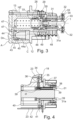
- Fig. 3 shows the master brake cylinder HZ with housing in which the HZ piston 33 and WS piston with spring for the counterforce and pedal characteristics are installed.
- the travel simulator piston can also be accommodated in block A or housing A.
- the piston also has redundant seals 45 with a throttle Dr to the interior. If the seal 45 fails, the failure is detected via the leakage flow and the failure is not relevant. This throttle Dr with a small leakage flow allows the failure of the first seal to be diagnosed.
- the travel simulator piston is supported on the flange 12 and therefore does not require a separate closure piece.
- the HZ piston 23 with return spring 50 is arranged parallel to the travel simulator piston.
- the piston can be guided in sliding rings 48 with low friction, and the sealing effect of the piston is also less impaired.
- a separate bearing part 49 is used for the sliding rings and seals, which is supported on the flange and also the stop of the piston 23 by means of a stop ring 28.
- a force-displacement sensor KWS 30 can be arranged in the HZ piston to diagnose the travel simulator WS.
- the sensor rods 31 and 31a are connected to the piston 23 and the pedal tappet. These rods are connected to a locking coupling 32-34, each with the piston and pedal tappet.
- This coupling consists of a ball 34 with a spring 33 in the housing 22. This prevents the pedal tappet from becoming blocked when a sensor rod is clamped.
- Fig. 4 shows the arrangement of two alternative designs of the pedal travel sensors.
- the first variant with rack 38, gear 37, drive shaft 36 to target 35 and sensor element 34 on PCB 23 has already been DE102015104246 described.
- This version requires little installation space and is cost-effective.
- a guide part 39 e.g. with a pin, is pressed into the sensor rod. This is guided in the upper part in a guide rail 40 so that any angular rotation is small, which affects the target 41.
- This target acts on an inductive sensor 42 with evaluation circuit and is connected to the main PCB 23 and sits in the ECU housing 14.
- DV1 for all variants a to f
- DV2 for all variants with redundant pressure supply
- HCU/ECU for the two variants without redundant pressure supply
- HZ and WS separate and integrated with pedal sensors for five of the six variants, with the exception of variant f. without master brake cylinder.
- MV for all variants Engine sensor: for all variants.
- the Figure 5 shows the basic elements of a controllable brake system consisting of a master brake cylinder HZ with travel simulator WS and storage container VB, a pressure supply device DV1, whereby the pressure supply device DV1 is an electromotive piston control.
- the pressure supply device DV1 acts together with a valve circuit on the wheel brake cylinders RZ, which transfer the controlled wheel pressure, e.g. in the case of ABS, to the Brake. This corresponds to the state of the art.
- the pressure can be regulated in both brake circuits BK1 and BK2 via the two connecting valves BP1 and BP2.
- hydraulic system according to the invention should have a high level of fault tolerance for semi-automatic (HAD) or fully automatic driving (FAD).
- HAD semi-automatic
- FAD fully automatic driving
- the pressure supply device DV1 acts from the brake circuit BK1 into the brake circuit BK2 via the hydraulic lines 1, 2 and 5 via the switching valves SV to the wheel brakes RB.
- the invention therefore provides two redundant valves BP1 and BP2 to enable the connection to the brake circuit BK2 from the first pressure supply device DV1.
- Dormant errors in the valves BP1 and BP2 are detected by the pressure sensor by short-circuiting the valves when the pressure changes. During this phase, the pressure must remain constant. If the first pressure supply device DV1 fails, e.g.
- valves are preferably normally open valves so that if the pressure supply device DV1 fails, the master brake cylinder HZ can act on both brake circuits BK1 and BK2. If pressure is reduced by opening the ZAV or FV valves, the two connecting switching valves open automatically due to the differential pressure acting without their own electrical control.
- the pedal movement is measured by redundant pedal travel sensors (PS), which are simultaneously connected to a KWS measuring element according to WO2012/059175 A1 act.
- PS pedal travel sensors
- the pressure supply device DV1 is controlled with the signal from the pedal travel sensors, whereby the piston control causes the volume flow in the main hydraulic line 1 in the brake circuit BK1 and via the redundant BP1 and BP2 valves into the brake circuit BK2.
- the master brake cylinder HZ can be connected to the brake circuits BK1 or BK2 via line 3, whereby the valve FV is arranged in line 3 to close it. This connection is only effective in the fallback level. If the line is connected to the connecting line of the two switching valves BP1 and BP2, the two valves BP1 and BP2 form a further redundancy. A usual connection from the FV directly into one of the two brake circuits BK1, BK2 would result in the brake circuit and thus the pressure supply acting on the HZ piston if the FV valve were leaking, which traditionally leads to the
- valve FV Different pressures or pressure levels from the master brake cylinder and the brake circuits BK1 and BK2 act on the valve FV. In the worst case, this can lead to, for example, failure of the on-board network or the control and control unit ECU that there is an unfavourable pressure difference at the closed valve FV and the valve FV cannot open, so that a pressure reduction P ab is not possible.
- another switching valve can be connected in parallel to the valve FV, with the outputs and inputs of the valves being connected to line 3 in reverse, so that for any pressure difference it is ensured that at least one of the two valves opens automatically due to the differential pressure, i.e. even without power.
- the dynamic pressure on the valves is advantageously reduced as a result. If the valve FV fails or leaks, the travel simulator WS does not fail.
- a leaky EV/SV causes the brake circuit or the entire pressure supply to fail.
- the valves BP2 and BP1 provide additional safety so that the pressure supply does not fail.
- a failure of the brake circuit BK1 due to a non-functioning switching valve SV means a failure of the pressure supply DV1, whereby the pressure supply to all wheel brakes that are still functioning is carried out via the other pressure supply device DV2.
- pressure supply When the pressure supply is active, pressure is always built up via the pressure supply.
- either the pressure supply or the central outlet valve ZAV can be used. Pressure is then reduced by retracting the piston of the pressure supply or by PWM operation of the ZAV.
- the pressure signal from the pressure sensor can be used to improve the control quality when the pressure is reduced via the ZAV valve.
- an outlet valve AV for at least one wheel brake as an alternative or in addition to the ZAV valve.
- the AV is preferably used on wheel brakes with a large volume, i.e. front wheel brakes.
- two outlet valves AV can be used instead of one outlet valve (not shown).
- an outlet valve AV can also be provided for each brake circuit, so that the pressure in this brake circuit is reduced via the outlet valve AV and at the same time the pressure in the another brake circuit is built up/reduced.
- the volume flow also goes through the valves BP1 or BP2, so that a leaky ZAV is not critical for normal operation, since if the central discharge valve ZAV fails, the pressure is controlled via the pressure supply device DV1.
- the error even if dormant, is immediately detected by the ZAV through a pressure change or increased volume delivery of the pressure supply device DV1.
- another discharge valve can also be connected in series to the outlet valve ZAV.
- the causes of failure in the master brake cylinder HZ and travel simulator WS are usually the seals.
- an additional seal D3 with a throttle can be used in the return line to the reservoir VB in order to be able to diagnose the failure of a seal at an early stage. This means that a leak can be detected via a small additional pedal movement via the pedal stroke sensors.
- the low stress on HAD and FAD must be taken into account.
- the pressure supply device DV1 can also be equipped with redundant seals, as with the master brake cylinder HZ before. described, can be equipped with D6 with a throttle between D6 and D5. If the suction valve is connected directly to the connection on PD1, then suction begins immediately on the piston's return stroke, with the advantage that high suction power is achieved even at low temperatures. A failure or leak in the SV will, in extreme cases, cause the DV to fail.
- a compromise is to connect the SV at around 60% of the stroke. This means that 40% of the stroke is possible without the effect of a leaky SV and at the same time a suction effect in the normal temperature range. With the small restriction mentioned above, the volume delivery of the piston is ensured by redundancy. Furthermore, the motor can be controlled via a redundant 2x3-phase winding, so that the DV only fails if the KGT blocks.
- ABS function via multiplex operation MUX and the pressure supply device DV1 is carried out as in WO 2006/111393 A1 described.
- Extended MUX functions are provided by a central discharge valve ZAV. If, when the pressure pauf is built up in the brake circuit BK1, a pressure reduction pab in the other brake circuit BK2 is required at the same time, this takes place via the central discharge valve ZAV and the simultaneously closed valve BP1. This means that the multiplex system MUX is only loaded by two wheel brakes RB1, RB2 in the brake circuit BK1, i.e. a pressure build-up Pauf and pressure reduction Pab cannot take place simultaneously in the wheel brakes RB1 and RB2 of the brake circuit BK1.
- a discharge valve AV1, AV2 can be used in the respective brake circuit to reduce the pressure pab in order to relieve the MUX.
- the discharge valve AV can be arranged or connected either between the switching valve SV and a connecting switching valve BP1, BP2 or between the wheel brake and the associated switching valve SV, so that a direct pressure reduction Pab can take place via the discharge valve to a storage container VB. This is particularly useful for reducing pressure Pab in the front wheels.
- the central discharge valve ZAV is not required with this alternative.
- pressure control is also carried out with ABS via volume measurement and via the piston movement of the pressure supply device DV1, also taking into account the pressure-volume characteristic curve (pV characteristic curve).
- pV characteristic curve the pressure-volume characteristic curve
- This also makes volume metering for pressure build-up possible. It is advantageous here to use a serial and not simultaneous pressure build-up p Pressure build-up p in the individual wheel brakes.
- the valve dimensioning and the dynamic pressure at the valve must be taken into account, particularly with the valves BP1 and BP2 when pressure builds up quickly in the wheel circuits.
- the dynamic pressure of the above-mentioned valves acts as a pressure difference between the brake circuits BK1 and BK2.
- the control and regulation unit ECU is part of the entire system and the packaging.
- a redundant or partially redundant ECU is necessary for fail-safe operation.
- This partially redundant ECU can also be used for certain functions in addition to the redundant ECU.
- the valves are or should be driven redundantly via separate valve drivers and isolating switches that switch off a failed valve driver.
- a redundant on-board power supply connection is also required for redundancy of the ECU control and regulation device.
- a 48V connection can also be used to connect the motors. The advantage of 48V is greater dynamics. If the motor from the pressure supply device DV1 fails at 48V, emergency operation with 12V with approx. 50% power is possible with reduced dynamics and cost savings. For this, the motor must be designed for 24V, for example.
- a pressure sensor DG is used in the brake circuit BK2, and possibly also in BK1. If the pressure sensor fails, pressure control can be achieved by measuring the current of the motors and controlling the position of the piston via the p-v characteristic curve.
- the pressure sensor DG1 can be used as Figure 5 shown. Alternatively, it can also be replaced or supplemented by one of the two pressure sensors DG2, DG3 shown in dashed lines.
- the pressure sensor DG2 should advantageously be used to measure the pressure in the connecting line VL. This makes it advantageous to control the pressure via the outlet valve AV and the pressure sensor DG2 when the pressure P ab in the brake circuit BK2 is reduced, if the pressure supply device DV1 in the brake circuit BK1 operates the pressure control, e.g. using a multiplex method.
- the pressure change in the brake circuit BK2 can be controlled via the pressure sensor DG2 and the second pressure supply device DV2, which is directly connected to line 5, provided the two connecting valves BP1 and BP2 are closed.
- the pressure supply device DV1 then controls, for example, via volume and current measurement. Calibration can, for example, always be carried out when the pressure supply device DV1 operates the pressure change in both brake circuits BK1 and BK2.
- a separating valve TVBK1 is arranged in line 4 so that the brake circuit can be separated again separately from the pressure supply DV1.
- Fig. 6a shows the application of a 2-circuit double-stroke piston, the forward stroke of which feeds BK1 via V1 and the return stroke via V2 feeds BK2.
- Both circuits of the DHK can feed into the other brake circuit BK via BP1 and BP2.
- the volume of the DHK must be as shown in WO2016/023994 A1und WO2016/023995 A1 known, via the valves V3 and V4 in the storage tank VB.
- the Figure 7 shows a schematic representation of a possible embodiment of a braking system with wheel brakes RB1 and RB2 on the front axle VA and the wheel brakes RB3 and RB4 on the rear axle, wherein an electric drive motor EM is provided to drive the rear axle HA.
- the braking system has only one pressure supply device DV1, one actuation device BE, and a higher-level control and regulating unit M-ECU.
- the pressure supply device DV1 has two independent control and regulating units DV-ECU1 and DV-ECU2, each of which controls one of the two winding or phase systems of the drive motor of the pressure supply device DV1, which are formed here by 3-phase systems.
- redundant signal lines DS1 and DS2 can be provided.
- Switching valves are provided for connecting or disconnecting the pressure supply device DV1 with the wheel brakes.
- the dashed lines represent signal transmission lines that connect the M-ECU control unit with the components of the braking system.
- the traction motor EM communicates with the control unit M-ECU and can be used to drive as well as brake the rear axle VA.
- a pressure supply device DV1 is used to build up pressure in the hydraulically acting wheel brakes RB1-RB4.
- This device has an electric motor drive M1 that is controlled by the control and regulating device DV-ECU.
- the pressure supply device DV1 can also have a motor current measuring device i/U, at least one temperature sensor T/U and a rotor angle sensor ⁇ /U, the signals of which can be used for pressure control.
- the motor M1 drives a piston KB via a spindle drive, which is movably mounted in a cylinder of the pressure supply device DV1 and delimits a pressure chamber, in order to build up, maintain or reduce pressure there.
- the pressure chamber is connected to the isolating valves TV1, TV2 via a hydraulic line.
- a brake circuit failure does not result in a total failure of the braking system. If the brake circuit BK1 fails, braking force can still be generated in the BK2 using the pressure supply and the electric motor EM. If the brake circuit BK2 fails, braking force can be generated in the brake circuit BK1 (front axle) using the driver's actuation unit or the pressure supply DV1. This means that the legal requirements for minimum deceleration can be met even if the brake circuit fails. Since the pressure supply is also redundant, a high level of availability can be achieved. The residual risk lies in the clamping of the spindle drive, which must be safeguarded by appropriate quality measures.
- the pressure in the hydraulic line can be determined using the pressure sensor p/U.
- the pressure can be regulated either using the pressure sensor p/U.
- the pressure can also be regulated using the current measurement using the motor current measuring device i/U and the angle sensor ⁇ /U and a stored Pressure-volume characteristic curve, since the motor torque is proportional to the pressure in the pressure chamber and also proportional to the motor current i.
- the M1 motor has two separate winding systems with 2x3 phases. Of course, the number of phases can be changed to suit the respective requirements. If one winding system fails, the M1 motor can still be operated with reduced power. This already creates a significant amount of redundancy.
- the DV-ECU control and regulating device can also be designed redundantly, so that, for example, an independent DV-ECU1 and DV-ECU2 control and regulating device can be provided, each of which controls a phase system of the M1 motor. This means that even if a DV-ECU1 or DV-ECU2 control and regulating device fails, the braking system can still be operated safely.
- the pressure supply device DV1 can be optionally connected to or separated from the hydraulic line HL6 or the first brake circuit BK1.
- the hydraulic lines HL1 and HL2 which are connected to the wheel brakes, can optionally be connected to the hydraulic line HL6. If pressure is to be built up in the wheel brake RB1 of the front axle VA, this is done via open valves TV and SV1, with the valves AV1, SV2 and FV closed and the piston KB adjusted by means of the motor M1.
- the piston KB can be retracted with the same valve switching or the outlet valve AV1 is opened, which allows the pressure in the wheel brake RB1 to be reduced into the reservoir VB.
- the pressure buildup in the wheel brake RB2 takes place in a similar way.
- the pressure in the wheel brakes RB1 and RB2 can also be built up and released simultaneously. It is also possible to build up pressure in one wheel brake using the pressure supply device DV1 and simultaneously reduce pressure in the other wheel brake using the associated outlet valve AV.
- the actuating device BE can be used to reduce pressure in one or both brake circuits.
- the actuating device BE has a brake pedal which acts on a piston that delimits a pressure chamber, whereby the piston then presses hydraulic medium from the pressure chamber into the brake circuit(s), whereby a brake pressure is built up in one or all of the wheel brakes.
- the switching valves are preferably designed as normally open valves.
- the Figure 8 shows another possible variant, where in contrast to the Figure 7 only one isolating valve TV1 is provided, which is located in the housing of the pressure supply device DV1.
- electric parking brakes EPB are provided on the rear axle HA as a further option for generating braking torque in the event of a fault. If the pressure supply DV1 fails, pressure can be built up in the wheel brakes RB1-RB4 in both brake circuits BK1 and BK2 using the main brake cylinder HZ via the normally open valve FV. If a wheel circuit fails, the respective switching valve assigned to the leak must be operated closed so that this does not lead to a complete failure of the brake system.
- the Figure 9 shows a variant in which only one isolating valve TV1 is provided, so that in contrast to the variant of the Figure 8 only in the brake circuit of the front axle VA, if the pressure supply device DV1 fails, pressure can be built up via the master brake cylinder HZ.
- the isolating valve is housed in the valve arrangement HCU.
- the failure of the pressure supply is not too critical, since an electric traction motor EM is available in the brake circuit BK2 and the actuation unit with master brake cylinder HZ is available in the brake circuit BK1 in the event of a failure of the pressure supply DV1.
- the Figure 10 shows a variant in which no electric motor is arranged on an axle and only a separating valve TV1 is provided. This allows, as with the variant of Figure 9 In an emergency, pressure can only be built up in the wheel brakes RB1 and RB2 in the brake circuit BK1 of the front axle VA via the master brake cylinder HZ, since the isolating valve TV1 is closed in this case in order to decouple the pressure supply device DV1 from the brake circuits. So that the ABS and/or ESP function can also be provided An additional outlet valve AV1 is provided on the wheel brake RB4 of the rear axle HA, through which the pressure in the wheel brake RB4 can be released directly into the reservoir VB.
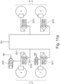
- the Figures 11a and 11b show an advantageous connection of the switching valves SV, which ensures that the switching valves SV open safely when there is a trapped pressure in the wheel brakes.
- the switching valves are connected with their connections assigned to the valve seat to the working chambers of the wheel brakes, so that the pressure trapped there pushes the valve actuator away from the valve seat of the switching valve SV.
- the Figure 11a shows the black and white arrangement and the Figure 11b the diagonal arrangement of the exhaust valves AV1 and AV2 assigned to the wheel brakes.
- Embodiment 2 Actuating device according to embodiment 1, characterized in that at least one electric parking brake (EPB) and/or one electric drive motor (EM) is/are provided for driving at least one axle of the vehicle, wherein the electric parking brake (EPB) and/or the electric drive motor send and/or receive signals to the electrical control unit (M-ECU).
- EPB electric parking brake
- EM electric drive motor
- Embodiment 3 Actuating device according to embodiment 2, characterized in that the electric parking brake (EPB) and/or the electric Drive motor (M) for generating an assisting braking force controlled by the electrical control unit (ECU).
- ECU electrical control unit
- Embodiment 4 Actuating device according to one of the preceding embodiments, characterized in that at least the actuating unit (BE) and/or the pressure supply (DV) has or have at least three seals arranged parallel to one another and at least two hydraulic connecting lines to the storage container (VB).
- Embodiment 5 Actuating device according to one of the preceding embodiments, characterized in that the pressure supply (DV) has redundant phase connections, redundant signal lines and/or redundant on-board network connections.
- the pressure supply (DV) has redundant phase connections, redundant signal lines and/or redundant on-board network connections.
- Embodiment 6 Actuating device according to one of the preceding embodiments, characterized in that the hydraulic connection of the HZ leads to a connection point (VP) between two series-connected solenoid valves (BPI) and (BP2), wherein solenoid valve (BPI) separates the brake circuit (BK1) from the master brake cylinder (HZ) and solenoid valve (BP1) separates the master brake cylinder (HZ) from the brake circuit (BK2).
- VP connection point
- Embodiment 7 Actuating device according to embodiment 6, characterized in that the series-connected solenoid valves (BPI, BP2) are designed to be open when de-energized and the connection point (VP) is hydraulically connected to the armature space of the valves (BP1, BP2).
- BPI, BP2 series-connected solenoid valves
- VP connection point
- Embodiment 8 Actuating device according to one of the preceding embodiments, characterized in that at least one pressure sensor (DG) is provided, which preferably measures the pressure at the connection point (VP).
- DG pressure sensor
- Embodiment 9 Actuating device according to one of the preceding embodiments, characterized in that a central outlet valve (ZAV) is provided at the connection point (VP), which is used in particular for pressure reduction in control operation (ABS).
- ZAV central outlet valve
- VP connection point
- ABS pressure reduction in control operation
- Embodiment 10 Actuating device according to embodiment 9, characterized in that the pressure sensor (DG) is used for controlled pressure reduction via the central outlet valve (ZAV).
- DG pressure sensor
- ZAV central outlet valve
- Embodiment 11 Actuating device according to one of the previous embodiments, that outlet valves (AVI, AV2) are only provided on the wheel brakes of the front axle (VA) and the outlet valves are arranged between the respective wheel brake and switching valve.
- Embodiment 12 Actuating device according to one of the previous embodiments, characterized in that the master brake cylinder (HZ) can be hydraulically connected to the front axle (VA) via a valve (FV) and can be separated from the pressure supply (DV1) and the rear axle brake circuit (BK2) via an isolating valve (TV1), and at least one electric drive motor (EM) is provided on the rear axle (HA) for brake force assistance, in particular in the event of failure of the pressure supply (DV1) or the brake circuit.
- HZ master brake cylinder
- V front axle
- BK2 rear axle brake circuit
- EM electric drive motor
- Embodiment 13 Actuating device according to one of the previous embodiments, characterized in that the master brake cylinder (HZ) can be hydraulically connected to the front axle (VA) via a valve (FV) and can be separated from the pressure supply (DV1) and the rear axle brake circuit (BK2) via a separating valve (TV1), and at least one electric drive motor (EM) is provided on the rear axle (HA) for generating braking force and the pressure supply from both brake circuits (BK1, BK2) can be separated via separating valves.
- the master brake cylinder (HZ) can be hydraulically connected to the front axle (VA) via a valve (FV) and can be separated from the pressure supply (DV1) and the rear axle brake circuit (BK2) via a separating valve (TV1), and at least one electric drive motor (EM) is provided on the rear axle (HA) for generating braking force and the pressure supply from both brake circuits (BK1, BK2) can be separated via separating valves.
- HZ master brake cylinder
- Embodiment 14 Actuating device according to one of the preceding embodiments, characterized in that the controllable switching valve (SV) is arranged such that a pressure present in a wheel brake (RB) applies force to the valve actuator of the switching valve (SV) away from its valve seat, Embodiment 15.
- Embodiment 16 Method for pressure control by means of an actuating device according to one of the preceding embodiments, characterized in that the pressure build-up and pressure reduction in brake booster operation are exclusively via the
- Embodiment 17 Method for pressure control by means of an actuating device according to one of the preceding embodiments or according to embodiment 16, characterized in that the pressure build-up and pressure reduction in recuperation mode via braking torque of the electric motors takes place exclusively via the piston control of the piston-cylinder unit (DV1) and the outlet valves (AV) are closed in this operating state
- Embodiment 18 Method for pressure control with active ABS or ESP function by means of an actuating device according to one of the preceding embodiments, characterized in that the pressure build-up takes place exclusively via the piston control of the piston-cylinder unit (DV1) in multiplex operation and the pressure build-up and pressure reduction takes place via opened/closed switching valves (SV) simultaneously or sequentially with closed exhaust valves and/or the pressure reduction takes place via the exhaust valve(s) (AV).
- DV1 piston control of the piston-cylinder unit
- SV opened/closed switching valves
- AV exhaust valve(s)
- Embodiment 19 Method according to embodiment 18, characterized in that when the pressure is reduced via outlet valves (AV1, AV2, ZAV), the pressure sensor (DG, DG1, DG2, DG3) is used to control the pressure reduction.
- AV1, AV2, ZAV outlet valves
- DG1, DG2, DG3 the pressure sensor
- Embodiment 20 Method according to embodiment 19, characterized in that the exhaust valves (AV, AVI, AV2) are operated either pulse width modulated or PWM-clocked or current-controlled and control the opening cross section of the exhaust valves (AV, AV1, AV2).
- Embodiment 21 Method for pressure control according to one of the preceding embodiments, characterized in that in pressure control the pressure-volume characteristic curve is used in particular for diagnosis and pressure change control or pre-control in the control.
- Embodiment 22 Method for pressure control according to one of the preceding embodiments, characterized in that at least one isolating valve is connected upstream of the pressure supply (DV1) and volume is fed in certain operating states (e.g. air inclusion, fading) from the storage container via a check valve and by retracting the piston of the pressure supply device.
- Embodiment 23 Method for pressure control according to one of the preceding embodiments, characterized in that during pressure control the current of the electric motor is used for pressure control, in particular if the pressure sensor has failed or the pressure sensor is used for pressure reduction control via outlet valve(s) (AV1, AV2, ZAV) while simultaneously pressure is built up via the pressure supply.
- Embodiment 24 Method for braking force control by means of an actuating device according to one of the preceding embodiments, characterized in that the braking force of the parking brake and/or the torque of the electric drive motor is used to decelerate the braking force, in particular in the event of module failure.
- Embodiment 26 Actuating device according to embodiment 25, characterized in that the sensor housing (52, 52a) extends from the housing (18) of the electronic control unit (ECU) up to beyond the axis (a DV1 ).
- Embodiment 27 Actuating device according to embodiment 26, characterized in that the region which surrounds the sensor housing (52, 52a) has a first region (52') which is located between the housing (18) of the electronic control unit (ECU) and the axis (a DV1 ) and a second region (52") which is located on the other side of the axis (a DV1 ), the second region (52") of the Sensor housing (52, 52a), in particular by means of a screw connection, is connected to the housing (62) of the electromotive drive.
- Embodiment 28 Actuating device according to one of the embodiments 25 to 27, characterized in that the inner housing part (52a) is supported on the motor housing (62), in particular is supported by means of a positive connection in an axial and/or a radial direction, and/or is fastened to the motor housing (62).
- Embodiment 29 Actuating device according to one of the preceding embodiments, characterized in that the housing (18) of the electronic control unit (ECU) is arranged or fastened to the motor housing (62) directly or via an intermediate part.
- ECU electronice control unit
- Embodiment 30 Actuating device according to one of the preceding embodiments, characterized in that the inner and outer housing parts (52, 52a) are connected to one another, in particular welded or glued to one another.
- Embodiment 31 Actuating device according to one of the preceding embodiments, characterized in that the inner and outer housing parts (52, 52a) are made of plastic.
- Embodiment 32 Actuating device according to one of the preceding embodiments, characterized in that a circuit board (22) is arranged in the sensor housing (52, 52a), on which in turn the sensor (34) is arranged.
- Embodiment 33 Actuating device according to embodiment 32, characterized in that the circuit board (22) is connected to a circuit board (23) of the electronic control unit (ECU) via a flexible cable connection or flexible circuit board (22a), which in particular has plug contacts or press-in contacts.
- ECU electronice control unit
- Embodiment 34 Actuating device according to one of the preceding embodiments, characterized in that the elastic part (61) serves to compensate for tolerances in up to three axes relative to the motor axis (a DV1 ).
- Embodiment 35 Actuating device according to one of the preceding embodiments, characterized in that a measuring means (53), in particular in Form of a disc, which rotates and in particular has markings on its side facing the outer sensor housing part (52), is provided with a coating and/or is profiled.
- a measuring means (53) in particular in Form of a disc, which rotates and in particular has markings on its side facing the outer sensor housing part (52), is provided with a coating and/or is profiled.
- Embodiment 36 Actuating device according to embodiment 35, characterized in that a closable opening (152), in particular by means of a closure plug (54), or a viewing window made of transparent material is arranged in the outer housing part (52) in such a way that the measuring means (53) is visible through the unlocked opening (152) or the viewing window or its eccentricity can be measured by means of a measuring device when the rotor (64) or threaded part (56) is rotating.
- Embodiment 37 Actuating device according to embodiment 35 or 36, characterized in that the axis of the measuring means (53) is arranged concentrically to the axis (a DV1 ) of the rotor (64) or the threaded part (56) and/or the measuring means (53) is fastened, in particular screwed or glued, to the front side of the rotor (64) or the threaded part (56).
- Embodiment 38 Actuating device according to one of the preceding embodiments, characterized in that the housing (18) of the electronic control unit (ECU) has a front side (ECU-V), a top side (ECU-O), a side wall (ECU-S) and a rear side (ECU-H), wherein a reservoir (VB) for hydraulic medium is arranged on the electronic control unit (ECU) or at a distance from it, wherein the reservoir (VB) has an opening (100) for filling in hydraulic medium, which opening can be closed, in particular by means of a cover (101), and which is arranged in particular in front of the front side (ECU-V) of the electronic control unit (ECU), wherein the reservoir (VB) surrounds the electronic control unit (ECU) from at least two, in particular at least three, sides (ECU-V, ECU-S, ECU-H) or extends at least partially along these sides.
- ECU-V front side
- ECU-O a top side
- ECU-S side
- Embodiment 39 Actuating device according to embodiment 38, characterized in that the storage container (VB) extends at least along at least a part of the side wall (ECU-S) and/or the top side (ECU-O) of the electronic control unit (ECU).
- the storage container (VB) extends at least along at least a part of the side wall (ECU-S) and/or the top side (ECU-O) of the electronic control unit (ECU).
- Embodiment 41 Actuating device according to one of the preceding embodiments, characterized in that the storage container (VB) has a front region (VBv), a middle region (VB M ) and a rear region (VB H ).
- Embodiment 42 Actuating device according to embodiment 41, characterized in that the front region (VBv) is arranged at least partially or completely in front of or laterally obliquely in front of the front side (ECU-V) of the electronic control unit (ECU) and the opening (100) is arranged in the front region (VBv).
- Embodiment 43 Actuating device according to embodiment 41 or 42, characterized in that the middle region (VB M ) extends laterally along the side wall (ECU-S) and/or the upper side (ECU-O) of the electronic control device (ECU).
- Embodiment 44 Actuating device according to one of the preceding embodiments, characterized in that the storage container (VB) extends laterally and/or at the top of the electronic control unit (ECU) from its front region (VBv) to the rear side (ECU-H) of the electronic control unit (ECU).
- the storage container (VB) extends laterally and/or at the top of the electronic control unit (ECU) from its front region (VBv) to the rear side (ECU-H) of the electronic control unit (ECU).
- Embodiment 45 Actuating device according to one of the embodiments 41 to 44, characterized in that the rear region (VB H ) of the storage container (VB) has a larger volume than the front region (VBv) and the middle region (VB M ), in particular such that it essentially serves to store the hydraulic medium of the actuating device.
- Embodiment 46 Actuating device according to one of the embodiments 41 to 45, characterized in that the rear region (VB H ) is arranged next to the rear side (ECU-H) of the electronic control unit (ECU).
- Embodiment 47 Actuating device according to one of the preceding embodiments, characterized in that the opening (100) is located above the rear region (VB H ) when installed in the vehicle.
- Embodiment 48 Actuating device according to one of the preceding embodiments, characterized in that the front side (ECU-V) of the electronic control device (ECU) faces away from a splash guard (SW) of a vehicle.
- ECU-V front side of the electronic control device
- SW splash guard
- Embodiment 49 Actuating device according to one of the preceding embodiments, characterized in that the surface normal (N) of the opening (100) is aligned vertically and/or at an angle ( ⁇ ) to a mounting flange (AF) of the actuating device, wherein the mounting flange (AF) serves to fasten the actuating device to a splash guard (SW), in particular such that the surface normal (N) is aligned vertically or in an angular range of 0° to 30° to the vertical when the actuating device is installed in the vehicle.
- a mounting flange AF
- SW splash guard
Landscapes
- Engineering & Computer Science (AREA)
- Transportation (AREA)
- Mechanical Engineering (AREA)
- Physics & Mathematics (AREA)
- Fluid Mechanics (AREA)
- Electromagnetism (AREA)
- Regulating Braking Force (AREA)
- Braking Systems And Boosters (AREA)
- Valves And Accessory Devices For Braking Systems (AREA)
- Braking Arrangements (AREA)
Abstract
Description
- Die vorliegende Erfindung betrifft eine Betätigungseinrichtung für ein ganz oder teilweise hydraulisch wirkendes Bremssystem für ein Fahrzeug, mit einem Hauptbremszylinder, der eine Kolben-Zylinder-Einheit mit einem Kolben und einem Arbeitsraum aufweist, wobei der Arbeitsraum hydraulisch mit einem Vorratsbehälter und einem Pedalgefühlsimulator verbunden oder verbindbar ist und mechanisch über eine Betätigungseinrichtung, insbesondere einem Bremspedal, verbunden ist und der Arbeitsraum über mindestens ein stromlos offenes Ventil mit mindestens einem Bremskreis verbindbar ist, und dass mindestens eine einem Bremskreis zugeordnete hydraulisch wirkende Radbremse, der je mindestens ein eigenes steuerbares Schaltventil zugeordnet ist, mit dem die Radbremse mit dem jeweiligen Bremskreis zum Druckaufbau und Druckabbau, insbesondere im Bremskraftverstärkerbetrieb verbindbar ist, sowie mit einer von einem Elektromotor angetriebenen Druckversorgung, deren Kolben mittels des Elektromotors im Zylinder verstellbar ist, mindestens einer Ventilanordnung mit Magnetventilen für eine radindividuelle Druckregelung, und mindestens einer elektrischen Steuereinheit zur Ansteuerung zumindest von Ventilen der Ventilanordnung und des Motors der Druckversorgung, sowie mindestens einem gesteuerten Auslassventil, über das direkt Hydraulikmedium, insbesondere bei ABS-Funktion oder Regelbetrieb, aus der jeweiligen Radbremse oder dem Bremskreis in den Vorratsbehälter ableitbar ist.
- Die Anforderungen, insbesondere Sicherheitsanforderungen beim halbautomatisiertem (HAD) und vollautomatisiertem (FAD) Fahren haben großen Einfluss auf die Systemgestaltung. Diese bedingen redundante und teilredundante Systeme und Komponenten.
- Im Vordergrund stehen hier die Druckversorgung, bei der die Bremskraft oder der Druckaufbau auch ohne Fahrerfuß gewährleistet sein muss. Entsprechend muss auch die elektronische Steuerung für diese Funktion ausgebildet sein. Für Level 3, insbesondere Level 4, muss ebenfalls die ABS-Funktion auch im Fehlerfalle gewährleistet sein.
- Bei einer redundanten Druckversorgung kann auch ein Systemkonzept ohne Tandem-HZ, nur mit sog. E-Pedal oder für Level 5 nur mit einem Bremsschalter ausgeführt werden. Hierbei sind folgende Patenanmeldungen erwähnenswert:
DE 10 2017 222 450 offenbart ein Hydrauliksystem mit nur einem Hauptzylinder, redundanter Druckversorgung, Trennventile zum Hauptzylinder und einen Wegsimulator. Ein Bypassventil zwischen den beiden Bremskreisen ermöglicht bei Ausfall einer Druckversorgung der zweiten Druckversorgung beide Bremskreise zu versorgen. Dieses stromlos offene Ventil ist extrem sicherheitsrelevant, da bei Ausfall des Ventils und z. B. Bremskreisausfall, ein Totalausfall der Bremse die Folge sein kann. Außerdem ist der Ventilaufwand sehr hoch. - Die
DE 10 2017 222 435 undDE 10 2016 225 537 zeigen ein ähnliches Konzept, jedoch mit E-Pedal, reduzierter Druckversorgung und Bypassventil. Alle Systeme verwenden für die ABS-Funktion beim Druckabbau ein sogenanntes Auslassventil. Gerät beim Öffnen des Ventils ein Schmutzpartikel in dessen Ventilsitz, so kann dies einen Bremskreisausfall bei der nächsten Bremsung bewirken. -
DE 10 2017 207 954 zeigt ein Systemkonzept mit redundanter Druckversorgung und ohne Auslassventile für die ABS-Druckregelung. Hier wird das sogenannte Multiplex-Verfahren, welches bereits inDE 102005055751 undDE 102009008944 A1 beschrieben ist, eingesetzt, bei dem die Drucksteuerung für ABS von der Druckversorgung durch Volumenmessung und Druckinformation erfolgt. Hierbei werden auch die Schaltventile zur Drucksteuerung redundant verwendet. Ein Sicherheitsrisiko entsteht, wenn die Kolbendichtung oder ein Rückschlagventil zum Vorratsbehälter ausfällt und das Schaltventil durch Schmutzpartikel undicht ist, was ebenso einen Totalausfall der Bremse zur Folge hat. - Oben genannte Beispiele zeigen das Problem der schlafenden Fehler, die bei Doppelfehlern kritisch werden, wenn diese nicht vor dem Bremsmanöver von der Diagnose erfasst werden können.
- Das Packaging oder Bauvolumen von Bremssystem ist ebenfalls von großer Bedeutung. Insbesondere bei Systemen mit HAD (halbautomatisiertem) und FAD (vollautomatisiertem Fahren) sind viele Varianten von Level 2 mit Tandemhauptzylinder (THZ) oder Single-Hauptzylinder (HZ) bis Level 5 ohne THZ oder HZ in der Gestaltung der Bauformgestaltung zu berücksichtigen. Insbesondere sind 3 - 5 Konzepte mit 2 Druckversorgungen bzw. Druckversorgungseinrichtungen (DV) im Packaging schwierig mit kleinem Bauvolumen zu realisieren. Beispiele für Packaging sind aus
EP 2744691 mit senkrechter Anordnung der Druckversorgung (DV) zur HZ-Achse undDE 2016032116160400 - Aus
DE102016105232 A1 ist ein Packaging mit kleinem Bauvolumen vorbekannt, bei dem eine integrierte redundante Druckversorgung bestehend aus mindestens einer Druckversorgungseinrichtung, mit Ventilen, insbesondere Magnetventilen zusammengefasst in einer Hydraulikunit, mit mindestens einer elektronischen Steuer- und Regeleinheit, mindestens einem Vorratsbehälter, und einem Hauptbremszylinder in einem Modul zusammengefasst ist. - Aufgabe der vorliegenden Erfindung ist es, eine sehr kostengünstige, kurz und schmal bauende 1-Box-Lösung für automatisiertes Fahren der Stufe 2 bis 3 zu schaffen, die zudem modular ist für andere darauf aufbauende Lösungen mit späterer Integration einer zweiten Druckversorgung.
- Diese Aufgabe wird mit einem System mit den Merkmalen des Anspruchs 1 gelöst. Vorteilhafte Ausgestaltungen des Systems nach Anspruch 1 ergeben sich durch die Merkmale der Unteransprüche.
- Es wird ein Packaging mit kleinem Bauvolumen vorgeschlagen mit integrierter Druckversorgung bestehend aus einer Druckversorgungseinrichtung, mit Ventilen, insbesondere Magnetventilen zusammengefasst in einer Hydraulikunit, mit mindestens einer elektronischen Steuer- und Regeleinheit, mindestens einem Vorratsbehälter, mit einem Single-Hauptbremszylinder und Pedalhubsensoren und Wegsimulator mit Kolben. Dabei sieht die Erfindung verschiedenen Varianten modular aufgebauter Betätigungssysteme für Bremssysteme vor, welche möglichst viele Gleichteile für Fertigung und Montage enthalten.
- Mögliche erfindungsgemäße Varianten sind vorzugsweise:
- Variante a:
Eine 1-Box Lösung mit nur einem Modul ist, welches eine Druckversorgungseinrichtung, die Ventilanordnung (HCU), Steuer- und Regeleinheit (ECU) und Vorratsbehälter (VB) umfasst, - Variante b:
Eine 1-Box Lösung mit nur einem Modul ist, welches die Druckversorgungseinrichtung aufweist, wobei mindestens eine Druckversorgungseinrichtung redundant, d.h. z.B. mit einem doppelten Bordnetzanschluss oder redundanten Phasenwicklungen ausgebildet ist und bei der die Ventilanordnung (HCU), Steuer- und Regeleinheit (ECU) und Vorratsbehälter (VB) ebenfalls im Modul enthalten sind. - Variante c:
Gleiches Modul wie bei Variante c. jedoch mit einer Steuer- und Regeleinheit welche voll oder teilredundanter ausgebildet ist. - Variante d:
Nutzung eines elektrischen Antriebsmotors und/oder einer elektrische Parkbremse für die Bremsung, insbesondere bei Ausfall von Modulen/Subsystemen. - Hierbei werden vorteilhaft die nachfolgend beschriebenen Gehäuse verwendet. Diese Gehäuse bilden Baugruppen, die zusammengebaut das gesamte Aggregat zum Einbau in das Fahrzeug bilden:
Gehäuse A: Umfasst die Ventilanordnung (HCU) für die Druckversorgungseinrichtung DV1 mit z.B. Ventilen (V), Magnetventilen (MV) und einem oder mehreren Druckgebern (DG). - Gehäuse B: Umfasst die Steuer- und Regeleinheit ECU ohne Redundanz mit einem Hauptstecker oder mit Teil- oder Vollredundanz mit zwei Steckern zum Bordnetz.
- Gehäuse C: Für HZ mit Pedalhubsensoren und kleiner Sensor-ECU und Vorratsbehälter VB für die Variante e. Der HZ beinhaltet auch das Pedalinterface (PI) zum Bremspedal und auch Wegsimulator mit Kolben und Feder.
- Das Gehäuse A (HCU) wird vorzugsweise aus fließgepresstem Formstück gefertigt, das sich sehr gut eignet zur Befestigung und Montage mit Verstemmtechnik. Hier soll die DV1 mit Kolbenantrieb und KGT zum Motor integriert werden, außerdem die Ventile und Magnetventile. Auch ist das Interface zur Steuer- und Regeleinheit ECU ähnlich zu ABS/ESP. Der Hauptbremszylinder HZ mit allen vorgenannten Komponenten (Gehäuse C) kann an Gehäuse A angeschraubt werden - dies gilt für alle Varianten außer für die Varianten e und f. Hier wird das Gehäuse C als Baugruppe separat vom Aggregat an die Stirnwand montiert und die Hydraulikleitung vom Hauptbremszylinder HZ an das Gehäuse A angeschlossen. Bei den Varianten a. und d. sitzt der Vorratsbehälter VB im Gehäuse A mit zwei Anschlüssen an die Bremskreise oder mit zusätzlichem Anschluss zur Druckversorgung DV. Der Schwimmer im Vorratsbehälter VB enthält ein Target mit Verbindung zum Sensorelement in der Steuer- und Regeleinheit ECU. Der Motor kann vorzugsweise über ein Zwischengehäuse, welches vorzugsweise aus Kunststoff ist, mit dem Gehäuse A verbunden werden. Der für die Kommutierung des Motors und Kolbenposition notwendige Sensor kann vorzugsweise in der Motorachse auf der zum Kolben gegenüberliegenden Seite am Motorgehäuse angebracht und mit der Steuer- und Regeleinheit ECU verbunden werden. Hierbei sitzt der Sensor in einem Zusatzgehäuse zur ECU. Als Redundanz zum elektrischen Anschluss der Magnetspule des Magnetventils kann zur Hauptleiterplatte PCB zusätzliche kleine Leiterplatte eingesetzt werden, für einen zweiten Anschluss der Magnetspule.
- Das dargestellte Packaging erfüllt die Anforderungen für Modularität und kleinem Bauvolumen und ist auch sehr günstig in Kosten und Gewicht.
- Durch das Vorsehen eines speziellen Sensorgehäuses ist es möglich, die fertigungsbedingten Toleranzen der Gehäuse der erfindungsgemäßen Einheit einfach auszugleichen, so dass der Motorsensor sicher an der für ihn vorgesehen Position platziert werden.
- Zudem kann durch eine spezielle Ausgestaltung des Vorratsbehälters dessen Einfüllstutzen bzw. -öffnung vorteilhaft an oder vor der Vorderseite des Gehäuses der elektronischen Steuereinheit bzw. der Betätigungsvorrichtung angeordnet werden, so dass sie gut erreichbar ist. Durch die seitlich am Gehäuse der elektronischen Steuereinheit vorbeiführende Verbindung des vorderen Einfüllstutzens hin zur Rückseite des Gehäuses der Steuereinheit kann der eigentlich Vorratsbehälter sinnvollerweise hinter der Steuereinheit angeordnet werden. Der seitliche bzw. mittlere Bereich des Vorratsbehälters kann vorteilhaft schmal ausgebildet werden, so dass die Betätigungsvorrichtung hierdurch nicht oder nur unwesentlich breiter baut als bei einem herkömmlichen Vorratsbehälter.
- Jeder Radbremse ist ein Schaltventil zugeordnet. Sofern keine zusätzlichen Auslassventile vorgesehen sind, so muss für eine Druckänderung in der jeweiligen Radbremse das zugehörige Schaltventil geöffnet werden, wobei die Druckversorgungseinrichtung durch entsprechende Bewegung ihres Kolbens den Druck auf- oder abbaut. Sobald der Druck in der Radbremse eingeregelt ist, wird das zugehörige Schaltventil wieder geschlossen und es kann in einer anderen Radbremse eine Druckänderung vorgenommen werden.
- Durch Vorsehen mindestens eines Auslassventils für mindestens eine Radbremse oder einen Bremskreis, ist es möglich, mit nur einer Druckversorgungseinrichtung eine hochdynamische ESP- und/oder ABS-Funktion bereitzustellen, wobei über die den Radbremsen zugeordneten Schaltventile der Druck aufgebaut wird. Über das einer Radbremse zugeordnete Auslassventil kann dann bei geschlossenem Schaltventil der Radbremse der Druck unmittelbar in den Vorratsbehälter abgebaut werden, wobei gleichzeitig mit der Druckversorgungseinrichtung eine Druckänderung in einer anderen Radbremse oder dem anderen Bremskreis vornehmbar ist.
- Auslassventile sollten insbesondere an hydraulischen Verbrauchern mit großen Volumen (z.B. an Radbremsen der Vorderachse) bzw. an zentraler Stelle zwischen Trennventilen, die Bremskreiskreise trennen (
Fig. 5 ) vorgesehen werden. Je nach Bremskreisgestaltung (diagonal oder schwarz-weiss) sind die Auslassventile an unterschiedlichen Stellen im Hydraulikkonzept angeordnet. - Im Bremskraftverstärkungsbetrieb sowie im Rekuperationsbetrieb wird Druck auf- und abgebaut über die Druckversorgung durch Vor- und Rückbewegung des Kolbens, die Auslassventile werden hier geschlossen betrieben. Im Regelbetrieb, z.B. bei ABS, wird primär das Multiplexverfahren nach
DE 102005055751 undDE 102009008944 A1 eingesetzt, nur bei extremen Dynamikanforderungen, wird das/die Auslassventile zum Druckabbau eingesetzt, wobei der Druckabbau vorzugsweise mit Unterstützung des Signals des Druckgebers erfolgt. Damit wird der Bremskreis nur in sehr wenigen Fällen zum Vorratsbehälter geöffnet, was entscheidende Vorteile bei der Zuverlässigkeit hat. Zudem werden die Schaltventile derart angeordnet ist, dass ein in einer Radbremse (RB) vorhandener Druck das Ventilstellglied des Schaltventils (SV) von dessen Ventilsitz weg kraftbeaufschlagt. - Wird zusätzliches Volumen für die Druckversorgung benötigt, wird Volumen aus dem Vorratsbehälter bei geschlossenen Trennventil der Druckversorgung zum Bremskreis nachgefördert.
- Nachfolgend werden verschiedene Varianten anhand von Zeichnungen näher erläutert.
- Es zeigen:
- Fig. 1:
- Seitenansicht einer erfindungsgemäßen integrierten Einheit mit den Gehäusen A, B, C und Vorratsbehälter VB und Pedalinterface (PI);
- Fig. 1a:
- eine Querschnittsdarstellung durch das Motorgehäuse, der elektronischen Steuereinheit sowie des Sensorgehäuses;
- Fig. 1b:
- platzsparende schematische Ausgestaltung eines Vorratsbehälters;
- Fig. 1c:
- Vorratsbehälter gemäß
Figur 7 mit schematisch dargestelltem Gehäuse der elektronischen Steuereinheit sowie dem Gehäuse für die Ventilanordnung; - Fig. 2:
- eine alternative Ausführungsform zu der Ausbildung des 1-Box-Moduls gemäß
Figur 1 ; - Fig. 2a:
- Vorderansicht des in
Figur 2 dargestellten Moduls; - Fig. 3:
- Schnitt durch den Hauptbremszylinder HZ, Wegsimulator WS und PI;
- Fig. 4:
- Darstellung der Pedalhubsensoren;
- Fig. 5
- Eine mögliche Ausführungsform eines erfindungsgemäßen Hydrauliksystems mit einer fehlersicheren Ventilanordnung zur Verbindung beider Bremskreise, einem Hauptzylinder mit Betätigungseinrichtung sowie mit nur einer Druckversorgungseinrichtungen mit elektronischer Steuer- und Regeleinrichtung als sogenannte Integrierte 1-Box-Anlage;
- Fig. 6:
- Hydrauliksystem mit nur einer Druckversorgung, die jedoch eine redundante Motorsteuerung aufweist;
- Fig. 6a:
- Hydrauliksystem gemäß
Figur 6 , jedoch mit einer Druckversorgungseinrichtung mit Doppelhubkolben; - Fig. 7:
- eine schematische Darstellung einer möglichen Ausführungsform eines Bremssystems mit Radbremsen an der Vorderachse und Hinterachse, wobei ein elektrischer Antriebsmotor die Hinterachse antreibt;
- Fig. 8-10:
- weitere Varianten möglicher Bremssysteme;
- Fig. 11a:
- Schwarz-weiß-Anordnung der Auslassventile;
- Fig. 11b:
- diagonale Anordnung der Auslassventile.
-
Fig. 1 zeigt die Seitenansicht der integrierten Einheit Gehäuse A mit Ventilanordnung HCU, welcher die Komponenten MV, Druckgeber DG, Kolben für DV1 und Befestigung des Motors von DV1 enthält. Die Komponenten wie z.B. Ventile, Magnetventil MV, Druckgeber DG sind vorzugsweise an einem Fließ- oder Strang gepressten Block 24 befestigt z.B. die MV vorzugsweise durch Verstemmen oder Clinchen, was auch dessen Abdichtung beinhaltet. Im unteren Teil ist der Kolben 8 der Druckversorgungseinheit DV1 mit Rückstellfeder und Gehäusedeckel 7 gezeigt, der z.B. vorzugsweise von nicht dargestellter Spindel und Kugelgewindetrieb KGT über den Motor 2 angetrieben wird. Dieser ist bei Gehäuse A über ein Zwischengehäuse 3 mit Befestigungsschrauben am HCU Block 24 angeschraubt. Der Vorratsbehälter VB2 ist mit zwei Anschlüssen 9a und 9b mit den Bremskreisen 1 und 2 verbunden. In Verlängerung von 9c ist im Gehäuse das Saugventil SV für die Druckversorgung DV platziert. - Der Vorratsbehälter VB weist einen Einfüllstutzen VBV mit einer mittels Deckel 101 verschließbaren Einfüllöffnung 100 auf, der sich vor das Gehäuse der ECU erstreckt, wobei sich seitlich am Gehäuse der ECU ein mittlerer Bereich VBM nach hinten zur Rückseite der Einheit erstreckt und in einem hinteren Bereich des Vorratsbehälters VBH mündet, so dass Hydraulikmedium vom Einfüllstutzen VBV in den hinteren Bereich VBH gelangen kann.
- Auf der gegenüberliegenden Seite ist das Sensorgehäuse 3 mit Drehwinkelsensor sowohl mit Motor 2 als auch ECU 18 über eine nicht dargestellte vorzugsweise flexible Leiterplatte mit dem Zwischengehäuse verbunden. Auf der Oberseite der Steuer- und Regeleinheit ECU sind die Stecker angebracht, die bei der redundanten ECU 2-fach ausgeführt sind. Bei der Variante mit separatem Hauptbremszylinder HZ ist mit 11 die entsprechende Verbindungsleitung zum Hauptbremszylinder HZ vorgesehen. Der Vorratsbehälter VB kann wie üblich einen Niveausensor (NS) mit Schwimmer beinhalten, wobei das Target mit Sensorelement in der Steuer- und Regeleinheit ECU angeordnet sind, welche vorzugsweise bei Level 4 und 5 redundant ausgeführt ist. Hinter dem Ventilanordnungsblock HCU ist in der vollintegrierten Version der Hauptbremszylinder HZ angeordnet, der mit Befestigungsschrauben 13 am HCU-Block 24 angeschraubt ist.
- Eine wichtige Komponente eines elektrischen Motorantriebes ist der Motorsensor 34 für die elektronische Kommutierung und Steuerung der Position des Kolbens. Der Motor kann mit verschiedenen Antriebsarten, z.B. Getriebe, Trapez oder Spindel 57 mit Kugelgewindetrieb 58, wie in
Fig. 1a gezeigt, kombiniert werden. - So können verschiedene Sensortypen, wie z.B. Segmentsensoren mit induktiven oder auch magnetfeldempfindlichen Sensoren, zum Einsatz kommen oder aber Sensoren, welche in der Motor- oder Getriebeachse angeordnet sind. Diese Sensoren sind besonders einfach im Aufbau, und setzen sich aus einem Sensortarget, z.B. in Form eines zwei- oder mehrpoliger Magneten, und einem magnetfeldempfindlichen Sensorelement, z.B. in Form eines Hallsensors, GMR-Sensors, o.ä. zusammen. Dieses Sensorelement 34 ist elektrisch mit der elektronischen Steuereinheit ECU verbunden, welche entweder unmittelbar oder über ein Zwischengehäuse an den Motor angebaut ist. Das Sensorelement 34 ist vorzugsweise in einem Sensorgehäuse bestehend aus einem äußeren Gehäuseteil 52 und einem inneren Gehäuseteil 52a zusammen und nimmt u.a. eine Leiterplatte 22 auf, auf der das Sensorelement 34 angeordnet sein kann.
- Um die verschiedenen Einbautoleranzen zwischen Gehäuse 18 der elektronischen Steuereinheit ECU, dem Motorgehäuse 62 und gegebenenfalls noch eines nicht dargestellten Zwischengehäuse und dem Sensorgehäuse 52/52a zu beherrschen, ist erfindungsgemäß ein elastisches Teil 61. Im Extremfall müssen dabei Toleranzen in allen drei Richtungen x, y, z ausgeglichen werden. Dies wird erfindungsgemäß durch einen entsprechenden Aufbau und Befestigung des Sensorgehäuses an dem Gehäuse 18 der elektronischen Steuereinheit ECU und an dem Motorgehäuse. Dabei ist das Sensorgehäuse vorteilhaft zweiteilig in ein äußeres Gehäuse 52 und ein inneres Gehäuse 52a unterteilt, wobei die Gehäuseteile 52, 52a über übliche Verbindungstechniken wie z.B. Schweißen oder Kleben miteinander verbunden und vorzugsweise aus Kunststoff gefertigt sind. Das Sensorgehäuse ist zudem am Motorgehäuse 62 befestigt, vorzugsweise an zwei Stellen. Die Sensorleiterplatte 22 ist im oberen Teil zur Steckerleiste flexibel, um die oben genannten Toleranzen zu beherrschen. Dazu eignet sich z.B. ein Flex-PCB (flexible Leiterplatte). Die elektrische Verbindung 22a von dieser flexiblen Leiterplatte 22 zur Hauptleiterplatte 23 der elektronischen Steuereinheit ECU erfolgt vorzugsweise über die besonders fehlersichere Steckerleiste 51 mit Einpresskontakten. Zur Montage mit der Hauptleiterplatte 23 besitzt das Gehäuse 18 der elektronischen Steuereinheit ECU eine Aussparung mit Deckel.
- Das Sensorgehäuse 52, 52a ist mit einem Vorsprung des ECU-Gehäuses 18 verbunden und daran fixiert. Dazwischen liegt ein elastisches Teil 61, welches z.B. eine flexible elastische Dichtung oder ein Dichtungsbalg sein kann. Vorzugsweise ist das elastische Teil als Lippendichtung ausgebildet ist. Diese flexible und elastische Dichtung 61 dient somit zum 3-achsigen Toleranzausgleich. Die elektrische Verbindung von der Motorwicklung zur Leiterplatte 23 erfolgt über eine übliche Steckkontaktierung.
- Diese in
Figur 1a dargestellte Sensoranordnung ermöglicht zusätzlich noch die Messung der Rotorexzentrizität, welche auf die Spindel wirkt und Querkräfte an dem Kolben 8 erzeugt. Zur Messung der Rotorexzentrizität dient ein auf dem Rotor oder der Spindelmutter 56 angeordnetes Vermessungsmittel 53, das im einfachsten Fall ein Messflansch oder eine Scheibe ist. Die Rotorexzentrizität wirkt sich auch in axialer Richtung aus und kann mit Lasertechnik gemessen werden. Hierzu besitzt das äußere Sensorgehäuseteil 52a eine Öffnung 152 in seinem unteren Bereich 52", die nach der Messung mit einem Verschlussstopfen 54 geschlossen wird. Die Oberfläche des Vermessungsmittels 53 kann auf seiner dem äußeren Sensorgehäuseteil 52 zugewandten Seite für die Messung Markierungen aufweisen, mit einer Beschichtung versehen und/oder profiliert sein. Der untere Bereich 52'' ist mittels einer Befestigungsschraube 55 an dem Motorgehäuse 62 befestigt. - Die
Figur 1b zeigt eine platzsparende schematische Ausgestaltung eines Vorratsbehälters VB, der einen vorderen Bereich VBV, einen mittleren Bereich VBM sowie einen hinteren Bereich VBH aufweist. Der vordere Bereich VBV weist eine obere Einfüllöffnung 100 auf, die mit dem Deckel 101 verschließbar ist. Wie inFigur 1c dargestellt, umgreift der Vorratsbehälter VB das Gehäuse B der elektronischen Steuereinheit ECU an drei Seiten, nämlich dessen Vorderseite ECU-V, dessen seitliche Wandung ECU-S sowie dessen Rück- bzw. Hinterseite ECU-H. Die Rückseite ECU-H ist der Spritzschutzwand SW zugewandt. Je nach Ausbildung der Einheit kann der Vorratsbehälter VB, wie in Figur 7a dargestellt, auch an der Rückwand des Gehäuses der Ventilanordnung HCU anliegen bzw. diese Hintergreifen. -
Figur 2 zeigt eine etwas abgewandelte Ausführungsform gegenüber der in Figur 1 dargestellten Einheit. -
Figur 2a zeigt die Ansicht von vorn. Hier wird gezeigt, dass die Umrißkontur noch innerhalb des kleinen Vakuum Vak. von 8" untergebracht werden kann und somit für den Einbau an der Spritzwand geeignet ist. Der große Vorteil liegt in der Baubreite von ca. 50 % von o.g. BKV, was für Rechts- und Linkslenker sehr günstig ist. Auch die Baulänge zu o.g. BKV ist erheblich kürzer, und bildet somit eine Basis für eine breite Anwendung des erfindungsgemäßen Modularkonzeptes. Hier sind auch wieder die verschiedenen Gehäuse A, B, C und VB vorzusehen. Gehäuse B liegt z.B. hinter dem HCU-Block 24 und wird mit diesem verschraubt und abgedichtet, wie bei ABS. - Vorteilhaft ist aus Kostengründen eine 1-teilige Leiterplatte PCB vorzusehen. Für den Fall des Eindringens von Wasser können die Leiterplatten PCB durch Stege mit Dichtung im Gehäuse der Steuer- und Regel ECU mit den beiden redundanten Schaltungen getrennt werden. Auch mögliche Leiterbahnrisse sind vorteilhaft durch Redundanzen abgedeckt bzw. ausgeschlossen. Wichtig sind auch die restlichen elektronischen Verbindungen von Motor zu Leiterplatte PCB.
-
Fig. 3 zeigt den Hauptbremszylinder HZ mit Gehäuse, in dem der HZ-Kolben 33 und WS-Kolben mit Feder für die Gegenkraft und Pedalcharakteristik eingebaut ist. Der Wegsimulatorkolben kann auch im Block A bzw. Gehäuse A untergebracht werden. Der Kolben besitzt ebenfalls redundante Dichtungen 45 mit Drossel Dr zum Innenraum. Bei Ausfall der Dichtung 45 wird über den Leckfluß der Ausfall erkannt und der Ausfall ist nicht relevant. Diese Drossel Dr mit kleinem Leckfluß erlaubt die Diagnose des Ausfalls der ersten Dichtung. Der Wegsimulator-Kolben stützt sich am Flansch 12 ab und benötigt deshalb kein getrenntes Verschlussstück. Parallel zum Wegsimulator-Kolben ist der HZ-Kolben 23 mit Rückstellfeder 50 angeordnet. Die Führung des Kolbens kann in Gleitringen 48 mit geringer Reibung erfolgen, auch wird hierbei die Dichtwirkung des Kolbens weniger beeinträchtigt. Vorzugsweise wird für die Gleitringe und Dichtungen ein getrenntes Lagerteil 49 verwendet, welches sich am Flansch abstützt und auch der Anschlag des Kolbens 23 mittels Anschlagring 28. Zur Diagnose des Wegsimulators WS kann im HZ-Kolben ein Kraft-Weg-Sensor KWS 30 angeordnet werden. Mit dem Kolben 23 und dem Pedalstößel sind die Sensorstangen 31 und 31a verbunden. Diese Stangen sind mit einer Rastkupplung 32-34 verbunden, jeweils mit Kolben und Pedalstößel. Diese Kupplung besteht aus Kugel 34 mit Feder 33 im Gehäuse 22. Damit wird eine Blockierung des Pedalstößels beim Klemmen einer Sensorstange vermieden. -
Fig. 4 zeigt die Anordnung von zwei alternativen Ausführungsmöglichkeiten der Pedalwegsensoren. Die erste Variante mit Zahnstange 38, Zahnrad 37, Antriebswelle 36 zum Target 35 und Sensorelement 34 auf PCB 23 wurde bereits inDE102015104246 beschrieben. Diese Version benötigt wenig Einbauraum und ist kostengünstig. Bei der unteren Variante ist ein Führungsteil 39 z.B. mit Zapfen in die Sensorstange eingepresst. Dieses wird im oberen Teil in einer Führungsleiste 40 geführt, damit eine Winkelverdrehung klein ist, was sich auf das Target 41 auswirkt. Dieses Target wirkt auf einen induktiven Sensor 42 mit Auswerteschaltung und ist mit der Haupt-PCB 23 verbunden und sitzt im ECU-Gehäuse 14. - Für die oben beschriebenen Varianten a bis f können folgende Komponenten vorteilhaft gleich ausgebildet sein:
DV1: für alle Varianten a bis f; DV2: für alle Varianten mit redundanter Druckversorgung; HCU/ECU: für die zwei Varianten ohne redundante Druckversorgung; HZ und WS: separat und integriert mit Pedalsensoren für fünf der sechs Varianten, mit Ausnahme von Variante f. ohne Hauptbremszylinder. Separater HZ jedoch mit zusätzlichem VB. MV: für alle Varianten Motorsensor: für alle Varianten. - Bis auf das E-Pedal entsprechend System f. sind alle Komponenten modular. Damit hat der Hersteller und Anwender einen modularen Systembaukasten (OEM) eine hervorragende Basis, auch für Kostenminimierung.
- Die
Figur 5 zeigt die Grundelemente eines regelbaren Bremssystems bestehend aus Hauptbremszylinder HZ mit Wegsimulator WS und Vorratsbehältnis VB, einer Druckversorgungseinrichtungen DV1, wobei die Druckversorgungseinrichtung DV1 eine elektromotorischer Kolbensteuerung ist. Die Druckversorgungseinrichtung DV1 wirkt zusammen mit einer Ventilschaltung auf die Radbremszylinder RZ, welche den geregelten Raddruck, z. B. bei ABS, auf die Bremse übertragen. Dies entspricht dem Stand der Technik. Mittels der einen Druckversorgungseinrichtung DV1 kann über die beiden Verbindungsventile BP1 und BP2 in beiden Bremskreisen BK1 und BK2 der Druck eingeregelt werden. - Das erfindungsgemäße Hydrauliksystem soll jedoch eine hohe Fehlersicherheit für halbautomatisches (HAD) oder vollautomatisches Fahren (FAD) aufweisen.
- Hierzu sollten alle ausfallrelevanten Komponenten berücksichtigt werden, wie z. B. Ventile, Sensoren, Dichtungen, Motoren, Bremskreise. Vorteilhaft sollten daher folgende Komponenten bzw. Hydraulikverbindungen ausfallsicher ausgebildet sein:
- (1) Verbindung von der für den ersten Bremskreis vorgesehenen Druckversorgungseinrichtung DV1 zum zweiten Bremskreis BK2;
- (2) Verbindung von dem Druckraum des Hauptbremszylinders HZ über das Ventil FV hin zu den Bremskreisen BK 1, BK2 über die Ventile BP1 und BP2;
- (3) Verbindung von Ventil PD1 und Ventil BD1 zu den Radbremszylindern RZ über die jeweiligen den Radbremsen zugeordneten Schaltventile SV;
- (4) Verbindung von Ventil BD2 zu den Radbremszylindern RZ über die jeweiligen den Radbremsen zugeordneten Schaltventile SV;
- (5) Verbindung von einem Bremskreis BK1, BK2 hin zum Vorratsbehältnis VB;
- (6) Verbindungen zwischen Bremskreisen BK1, BK2 hin zu den Radbremszylindern RZ.
- Diese hydraulischen Verbindungen mit möglichen Ausfallfehlern der einzelnen Komponenten werden im Folgenden beschrieben.
- Die Druckversorgungseinrichtung DV1 wirkt vom Bremskreis BK1 in den Bremskreis BK2 über die Hydraulikleitungen Leitung 1, 2 und 5 über die Schaltventile SV zu den Radbremsen RB. Im Stand der Technik wird hierzu lediglich ein einziges Bypassventil eingesetzt. Ein Ventilausfall kann hier einen Totalausfall der Bremse bewirken, wenn noch ein schlafender Fehler bei einem weiteren Ventil hinzukommt. Die Erfindung sieht daher zwei redundante Ventile BP1 und BP2 vor, um die Verbindung hin zum Bremskreis BK2 von der ersten Druckversorgungseinrichtung DV1 zu ermöglichen. Schlafende Fehler der Ventile BP1 und BP2 werden vom Druckgeber erkannt, indem bei Druckänderung die Ventile kurzgeschlossen werden. In dieser Phase muss der Druck konstant bleiben. Bei Ausfall der ersten Druckversorgungseinrichtung DV1, z.B. bei Ausfall einer Kolbendichtung, wird eine Rückwirkung auf Bremskreis BK2 über die drei redundanten Ventile BP1, BP2 und PD1 verhindert. Die Ventile sind vorzugsweise stromlos offene Ventile, damit bei Ausfall der Druckversorgungseinrichtung DV1 der Hauptbremszylinder HZ auf beide Bremskreise BK1 und BK2 wirken kann. Wird Druck über das Öffnen der Ventile ZAV oder FV reduziert, so öffnen die beiden Verbindungsschaltventile ohne eigene elektrische Ansteuerung durch den wirkenden Differenzdruck selbstständig.
- Die Pedalbewegung wird über redundante Pedalwegsensoren (PS) gemessen, die zugleich auf ein KWS-Messelement nach
WO2012/059175 A1 wirken. Mit dem Signal der Pedalwegsensoren wird die Druckversorgungseinrichtung DV1 angesteuert, wobei die Kolbensteuerung den Volumenfluss in der Hydraulikhauptleitung 1 in dem Bremskreis BK1 und über die redundanten BP1- und BP2-Ventile in den Bremskreis BK2 bewirkt. Über die Leitung 3 kann der Hauptbremszylinder HZ mit den Bremskreisen BK1 oder BK2 verbunden sein, wobei in der Leitung 3 das Ventil FV zum Verschließen derselben angeordnet ist. Diese Verbindung ist nur in der Rückfallebene wirksam. Sofern die Leitung mit der Verbindungsleitung der beiden Schaltventile BP1 und BP2 verbunden ist, bilden die beiden Ventile BP1 und BP2 eine weitere Redundanz. Eine übliche Verbindung vom FV direkt in einen der beiden Bremskreise BK1, BK2 hätte bei undichtem Ventil FV zur Folge, dass der Bremskreis und damit die Druckversorgung auf den HZ-Kolben wirkt, was herkömmlich zum Abschalten der Druckversorgung führt. - Auf das Ventil FV wirken verschiedene Drücke bzw. Druckniveaus vom Hauptbremszylinder und von den Bremskreisen BK1 und BK2. Dies kann dazu im schlimmsten Fall dazu führen, z.B. bei Ausfall des Bordnetzes oder der Steuer- und Regeleinheit ECU, dass eine ungünstige Druckdifferenz am geschlossenen Ventil FV herrscht und das Ventil FV nicht öffnen kann, so dass ein Druckabbau Pab nicht möglich ist. Um dies zu verhindern kann dem Ventil FV ein weiteres Schaltventil parallelgeschaltet werden, wobei die Aus- und Eingange der Ventile vertauscht an die Leitung 3 angeschlossen sind, so dass bei beliebigen Druckdifferenzen sichergestellt ist, dass zumindest eines der beiden Ventile durch den Differenzdruck automatisch, d.h. auch ohne Bestromung öffnet. Zudem wird der Staudruck an den Ventilen hierdurch vorteilhaft verringert. Bei Ausfall bzw. Undichtigkeit des Ventils FV fällt der Wegsimulator WS nicht aus.
- Bei Ausfall eines Bremskreises im Radzylinder wird herkömmlich das entsprechende Einlassventil EV oder Schaltventil SV geschlossen, damit wird der ausgefallene Radkreis eliminiert. Ein undichtes EV/SV (schlafender Fehler) bewirkt den Ausfall des Bremskreises oder der gesamten Druckversorgung. Auch hier ist durch die Ventile BP2 und BP1 eine zusätzliche Sicherheit gegeben, so dass die Druckversorgung nicht ausfällt. Ein Ausfall des Bremskreises BK1 aufgrund eines nicht funktionierenden Schaltventils SV bedeutet einen Ausfall der Druckversorgung DV1, wodurch die Druckversorgung aller noch funktionstüchtigen Radbremsen über die andere Druckversorgungseinrichtung DV2 erfolgt.
- Der Druckaufbau erfolgt bei aktiver Druckversorgung immer über die Druckversorgung. Für die ABS-Regelung oder zur Druckreduzierung mit der Druckversorgungseinrichtung DV1 kann entweder die Druckversorgung oder das zentrale Auslassventil ZAV verwendet werden. Druckabbau erfolgt dann durch Rückfahren des Kolbens der Druckversorgung oder durch PWM-Betrieb des ZAV. Zur Verbesserung der Regelgüte beim Druckabbau über das ZAV-Ventil kann das Drucksignal des Druckgeber eingesetzt werden. Es ist jedoch ebenso möglich, alternativ oder ergänzend zum ZAV-Ventil für zumindest eine Radbremse ein Auslassventil AV vorzusehen, vorzugsweise wird das AV an den Radbremsen mit großem Volumen, d.h. Vorderradbremsen eingesetzt. So können statt einem Auslassventil auch zwei Auslassventile AV eingesetzt werden (nicht eingezeichnet). Auch kann wie in Standard-ABS-Systemen üblich für jeden Bremskreis, ein Auslassventil AV vorgesehen werden, so dass in diesem Bremskreis über das Auslassventil AV der Druck abgebaut wird und gleichzeitig der Druck mittels der Druckversorgungseinrichtung DV1 in dem anderen Bremskreis aufgebaut/abgebaut wird. Der Volumenfluss geht dabei zusätzlich über die Ventile BP1 oder BP2, so dass ein undichtes ZAV nicht kritisch für den Normalbetrieb ist, da bei Ausfall des zentralen Abführventils ZAV die Drucksteuerung über die Druckversorgungseinrichtung DV1 erfolgt. Außerdem wird der Fehler, auch schlafend, von ZAV gleich durch Druckänderung oder erhöhte Volumenförderung der Druckversorgungseinrichtung DV1 erkannt. Für extreme Sicherheitsanforderungen kann auch ein weiteres Abführventil zum Auslassventil ZAV in Reihe geschaltet werden.
- Ausfallursachen im Hauptbremszylinder HZ und Wegsimulator WS sind normalerweise die Dichtungen. Beim Hauptbremszylinder HZ kann eine zusätzliche Dichtung D3 mit Drossel in der Rücklaufleitung zum Vorratsbehälter VB eingesetzt werden, um den Ausfall einer Dichtung frühzeitig diagnostizieren zu können. Damit ist eine Undichtheit über eine kleine zusätzliche Pedalbewegung über die Pedalhubsensoren erkennbar. Zu berücksichtigen ist die geringe Beanspruchung bei HAD und FAD.
- Zur Diagnose der Dichtungen ist bei vielen Systemen in der Rücklaufleitung ein stromlos offenes Magnetventil eingeschaltet, welches zur Diagnose geschlossen wird. Hierbei wird von der Druckversorgungseinrichtung DV1 über die Ventile PD1, BP1 und EV Druck in den Hauptbremszylinder HZ geleitet. Die Diagnose erfolgt über Druckänderung bei konstanter Kolbenposition oder Änderung der Kolbenposition bei konstantem Druck. Als Alternative kann hier auch eine Kombination aus Drossel- und Rückschlagventil kostensparend eingesetzt werden. Die Drossel ist so bemessen, dass ein Leckfluss durch die Dichtung nur geringfügig zur Pedalverlängerung innerhalb einer normalen Bremszeit von ca. 10 sec. führt.
- Dieselbe Lösung wird auch beim WS-Kolben mit redundanter Dichtung eingesetzt, Diagnose wie o. g. bei D3 über die Pedalbewegung. Hinzu kommt noch, dass eine Steuerung der Bremskraftverstärkung auch bei diesen ausgefallenen Dichtungen noch möglich ist, allerdings mit veränderter Pedalcharakteristik. Auch hier gilt eine extrem kleine Ausfallrate für den Ausfall von zwei Dichtungen fast im Bereich <10-10/Jahr. Auch die Druckversorgungseinrichtung DV1 kann mit redundanten Dichtungen, wie beim Hauptbremszylinder HZ zuvor beschrieben, ausgerüstet werden mit D6 mit Drossel zwischen D6 und D5. Wenn das Saugventil direkt mit dem Anschluss an PD1 verbunden wird, dann setzt das Ansaugen unmittelbar beim Rückhub des Kolbens ein, mit dem Vorteil, dass auch bei tiefen Temperaturen eine hohe Saugleistung gegeben ist. Ein Ausfall, Undichtheit des SV bewirkt im Grenzfall Ausfall der DV. Ein Kompromiss liegt in dem Anschluss des SV bei ca. 60 % des Hubes. Damit ist 40% des Hubes ohne Auswirkung eines undichten SV möglich und zugleich eine Saugwirkung im normalen Temperaturbereich. Mit kleiner o. g. Einschränkung ist durch Redundanz die Volumenförderung des Kolbens gesichert. Weiterhin kann der Motor über eine redundante 2x3-Phasen-Wicklung angesteuert werden, so dass die DV nur durch blockierendes KGT ausfallen.
- Die ABS-Funktion über Multiplexbetrieb MUX und der Druckversorgungseinrichtung DV1 erfolgt wie in
WO 2006/111393 A1 beschrieben. Erweiterte MUX-Funktionen ergeben sich durch ein zentrales Abführventil ZAV. Ist beim Druckaufbau pauf im Bremskreis BK1 gleichzeitig ein Druckabbau pab im anderen Bremskreis BK2 notwendig, so erfolgt dieser über das Abführventil zentrale ZAV und gleichzeitig geschlossenem Ventil BP1. Dadurch ist das Multiplexsystem MUX nur durch zwei Radbremsen RB1, RB2 im Bremskreis BK1 belastet, d. h. es kann nicht zugleich ein Druckaufbau Pauf und Druckabbau Pab in den Radbremsen RB1 und RB2 des Bremskreises BK1 erfolgen. Alternativ kann auch ein Abführventil AV1, AV2 im jeweiligen Bremskreis zum Druckabbau pab zur Entlastung des MUX verwendet werden. Dabei kann das Abführventil AV entweder zwischen dem Schaltventil SV und einem Verbindungsschaltventil BP1, BP2 oder aber zwischen der Radbremse und dem zugehörigen Schaltventil SV angeordnet bzw. angeschlossen werden, so dass ein direkter Druckabbau Pab über das Abführventil hin zu einem Vorratsbehälter VB erfolgen kann. Dies ist insbesondere zum Druckabbau Pab in den Vorderrädern sinnvoll. Das zentrale Abführventil ZAV wird bei dieser Alternative nicht benötigt. - Typisch ist für den o. g. MUX-Betrieb die Druckregelung auch bei ABS über die Volumenmessung und über die Kolbenbewegung der Druckversorgungseinrichtung DV1, auch unter Berücksichtigung der Druck-Volumen-Kennlinie (p-V-Kennlinie). Somit ist auch eine Volumenzumessung für den Druckaufbau möglich. Vorteilhaft ist hier beim Druckaufbau pauf ein serieller und nicht gleichzeitiger Druckaufbau pauf in den einzelnen Radbremsen. Zu berücksichtigen ist dabei die Ventildimensionierung und der Staudruck am Ventil, insbesondere bei den Ventilen BP1 und BP2 bei schnellem Druckaufbau in den Radkreisen. Der Staudruck von o. g. Ventilen wirkt als Druckdifferenz zwischen den Bremskreisen BK1 und BK2.
- Die Steuer- und Regeleinrichtung ECU ist Bestandteil des gesamten Systems und des Packagings. Für eine fehlersichere Funktion ist eine redundante oder teilredundante ECU notwendig. Diese teilredundante ECU kann auch für bestimmte Funktionen zusätzlich zur redundanten ECU verwendet werden. In jedem Fall sind bzw. sollten die Ventile redundant über getrennte Ventiltreiber und Trennschalter angetrieben, der einen ausgefallenen Ventiltreiber abschaltet.
- Zur Redundanz der Steuer- und Regeleinrichtung ECU ist auch ein redundantes Bordnetzanschluss notwendig. Auch kann ein Anschluss mit 48V für den Anschluss der Motoren verwendet werden. Vorteil bei 48V ist eine höhere Dynamik. Bei Ausfall des Motors von der Druckversorgungseinrichtung DV1 bei 48V ist Notbetrieb mit 12V mit ca. 50% Leistung gegeben mit red. Dynamik und Kostenersparnis. Hierzu ist eine Auslegung des Motors auf z.B. 24V notwendig.
- Vorzugsweise wird im Bremskreis BK2 ein Druckgeber DG, ggf. auch in BK1 eingesetzt. Bei Ausfall des Druckgebers kann eine Druckregelung über die Strommessung der Motoren und Positionssteuerung des Kolbens über die p-v-Kennlinie erfolgen.
- Der Druckgeber DG1 kann wie in der
Figur 5 dargestellt angeordnet werden. Alternativ kann er jedoch auch durch einen der beiden gestrichelt dargestellten Druckgeber DG2, DG3 ersetzt oder ergänzt werden. Vorteilhaft sollte der Druckgeber DG2 verwendet werden, um den Druck in der Verbindungsleitung VL zu messen. Hierdurch kann vorteilhaft beim Druckabbau Pab im Bremskreis BK2 der Druck über das Auslassventil AV und den Druckgeber DG2 gesteuert werden, wenn die Druckversorgungseinrichtung DV1 im Bremskreis BK1 z.B. mittels Multiplexverfahren die Druckregelung betreibt. - Sofern zwei Druckversorgungseinrichtungen DV1 und DV2 verwendet werden, so kann im Bremskreis BK2 über den Druckgeber DG2 und die zweite Druckversorgungseinrichtung DV2, welche direkt mit der Leitung 5 in Verbindung ist, die Druckänderung gesteuert werden, sofern die beiden Verbindungsventile BP1 und BP2 geschlossen sind. Die Druckversorgungseinrichtung DV1 steuert dann z.B. über Volumen- und Strommessung. Eine Kalibrierung kann z.B. immer dann erfolgen, wenn die Druckversorgungseinrichtung DV1 die Druckänderung in beiden Bremskreisen BK1 und BK2 betreibt.
- Die in den
Figuren 6 und 6a dargestellten Ausführungsformen sind leicht gegenüber der inFigur 5 dargestellten Ausführungsform abgewandelt. - So ist bei der Ausführungsform gemäß
Figur 6 in der Leitung 4 ein Trennventil TVBK1 angeordnet, damit der Bremskreis separat noch einmal der Druckversorgung DV1 getrennt werden kann. -
Fig. 6a zeigt die Anwendung eines 2-kreisigen Doppelhubkolbens, dessen Vorhub über V1 den BK1 speist und der Rückhub über V2 den BK2. Beide Kreise des DHK können über die BP1 und BP2 in den jeweils anderen Bremskreis BK einspeisen. Zum Pab muss das Volumen des DHK, wie ausWO2016/023994 A1undWO2016/023995 A1 bekannt, über die Ventile V3 und V4 in der Vorratsbehälter VB abgeführt werden. - Die
Figur 7 zeigt eine schematische Darstellung einer möglichen Ausführungsform eines Bremssystems mit Radbremsen RB1 und RB2 an der Vorderachse VA und den Radbremsen RB3 und RB4 an der Hinterachse, wobei ein elektrischer Antriebsmotor EM zum Antrieb der Hinterachse HA vorgesehen ist. - Das Bremssystem hat lediglich eine einzige Druckversorgungseinrichtung DV1, eine Betätigungseinrichtung BE, eine übergeordneten Steuer- und Regeleinheit M-ECU. Die Druckversorgungseinrichtung DV1 verfügt über zwei voneinander unabhängige Steuer- und Regeleinheiten DV-ECU1 und DV-ECU2, die jeweils die Ansteuerung von jeweils einem der beiden Wicklungs- bzw. Phasensysteme des Antriebsmotors der Druckversorgungseinrichtung DV1, welche hier durch 3-Phasensysteme gebildet sind, ansteuern. Zusätzlich können redundante Signalleitungen DS1 und DS2 vorgesehen werden.
- Schaltventile zum Verbinden bzw. Trennen der Druckversorgungseinrichtung DV1 mit den Radbremsen sind vorgesehen sind. Die gestrichelten Linien stellen Signalübertragungsleitungen dar, welche die Steuereinheit M-ECU mit den Komponenten des Bremssystems verbinden.
- Der Traktionsmotor EM kommuniziert mit der Steuereinheit M-ECU und kann zum Antrieb als auch zum Abbremsen der Hinterachse VA eingesetzt werden kann.
- Zum Druckaufbau in den hydraulisch wirkenden Radbremsen RB1-RB4 dient eine Druckversorgungseinrichtung DV1, die einen elektromotorischen Antrieb M1 aufweist, welcher von der Steuer- und Regeleinrichtung DV-ECU gesteuert wird. Zusätzlich kann die Druckversorgungseinrichtung DV1 noch über ein Motorstrom-Meßeinrichtung i/U, mindestens einen Temperatursensor T/U sowie eine Rotor-Winkelgeber · /U aufweisen, deren Signale zur Druckregelung verwendet werden können. Der Motor M1 treibt über einen Spindeltrieb einen Kolben KB, welcher in einem Zylinder der Druckversorgungseinrichtung DV1 verschieblich gelagert ist und einen Druckraum begrenzt, an, um dort einen Druck aufzubauen, zu halten oder abzubauen. Der Druckraum ist über eine Hydraulikleitung mit den Trennventilen TV1, TV2 in Verbindung. Durch die beiden der Druckversorgung DV1 vorgeschalten Trennventile wirkt sich ein Bremskreisausfall nicht auf den Totalausfall der Bremsanlage aus. Bei Ausfall des Bremskreises BK1, kann immer noch im BK2 mittels der Druckversorgung und den Elektromotor EM Bremskraft erzeugt werden. Fällt Bremskreis BK2 aus, kann im Bremskreis BK1 (Vorderachse) mittels der Betätigungseinheit durch den Fahrer oder der Druckversorgung DV1 Bremskraft erzeugt werden. Damit können die gesetzlichen Anforderungen der Mindestverzögerung auch bei Bremskreisausfall erreicht werden. Da die Druckversorgung zudem redundant ausgeführt ist, kann eine hohe Verfügbarkeit erreicht werden. Restrisiko liegt beim Klemmen des Spindeltrieb, was durch entsprechend Qualitätsmaßnahmen abgesichert werden muss. Mittels des Druckgebers p/U kann der Druck in der Hydraulikleitung ermittelt werden. Die Druckregelung kann entweder unter Zuhilfenahme des Druckgebers p/U erfolgen. Die Druckregelung kann aber auch über die Strommessung mittels der Motorstrom-Meßeinrichtung i/U sowie dem Winkelgeber · /U und einer abgespeicherten Druck-Volumen-Kennlinie erfolgen, da das Motormoment proportional zum Druck im Druckraum und auch proportional zum Motorstrom i ist. Der Motor M1 verfügt über zwei voneinander getrennte Wicklungssysteme mit 2x3-Phasen. Selbstverständlich kann die Zahl der Phasen den jeweiligen Anforderungen nach geändert werden. Bei Ausfall eines Wicklungssystems kann der Motor M1 noch mit verminderter Leistung betrieben werden. Hierdurch ist bereits eine wesentliche Redundanz geschaffen. Die Steuer- und Regeleinrichtung DV-ECU kann ebenfalls redundant ausgebildet werden, so dass z.B. jeweils eine eigenständige Steuer- und Regeleinrichtung DV-ECU1 und DV-ECU2 vorgesehen sein kann, welche jeweils ein Phasensystem des Motors M1 ansteuert. Somit kann auch bei Ausfall einer Steuer- und Regeleinrichtung DV-ECU1 bzw. DV-ECU2 das Bremssystem noch sicher betrieben werden.
- Mittels der Trennventile TV1, TV2 kann die Druckversorgungseinrichtung DV1 wahlweise mit der Hydraulikleitung HL6 bzw. dem ersten Bremskreis BK1 verbunden bzw. von dieser getrennt werden. Mittels Schaltventilen SV1 und SV2 sind die Hydraulikleitungen HL1 und HL2, welche mit den Radbremsen verbunden sind, wahlweise mit der Hydraulikleitung HL6 verbindbar. Soll nun ein Druck in der Radbremse RB1 der Vorderachse VA aufgebaut werden, so erfolgt dies über geöffnete Ventile TV und SV1 wobei die Ventile AV1, SV2 und FV geschlossen sind und der Kolben KB mittels des Motors M1 verstellt wird. Zum Druckabbau in der Radbremse RB1 kann der Kolben KB bei gleicher Ventilschaltung zurückgefahren werden oder aber das Auslassventil AV1 wird geöffnet, wodurch sich der Druck in der Radbremse RB1 in den Vorratsbehälter VB abbauen kann. Der Druckaufbau in der Radbremse RB2 erfolgt analog. Selbstverständlich kann der Druck in den Radbremsen RB1 und RB2 auch simultan aufgebaut und abgebaut werden. Auch ist ein Druckaufbau in der einen Radbremse mittels der Druckversorgungseinrichtung DV1 und gleichzeitig ein Druckabbau in der anderen Radbremse über das zugehörige Auslassventil AV möglich. Bei alleinigem Druckaufbau in den Radbremsen RB3 und RB4 des zweiten Bremskreises BK2 muss entweder das Trennventil TV und/oder die Schaltventile SV1 und SV2 geschlossen und das jeweilige Schaltventil SV3 bzw. SV3 geöffnet sein. Sollte die Druckversorgungseinrichtung DV1 ausfallen, so kann mittels der Betätigungseinrichtung BE ein Druck in einem oder beiden Bremskreisen aufgebaut werden. Hierfür weist die Betätigungseinrichtung BE ein Bremspedal auf, welches auf einen Druckraum begrenzenden Kolben wirkt, wobei durch den Kolben dann aus dem Druckraum Hydraulikmedium in den bzw. die Bremskreise gedrückt wird, wodurch ein Bremsdruck in einer oder allen Radbremsen aufgebaut wird. Hierfür sind die Schaltventile vorzugsweise als Stromlos-Offene-Ventile ausgebildet.
- Die
Figur 8 zeigt eine weitere mögliche Variante, wobei im Gegensatz zurFigur 7 nur ein Trennventil TV1 vorgesehen ist, welches in dem Gehäuse der Druckversorgungseinrichtung DV1 angeordnet ist. Zusätzlich sind an der Hinterachse HA elektrische Parkierbremsen EPB als weitere Möglichkeit zur Erzeugung von Bremsmoment für den Fehlerfall vorgesehen. Bei Ausfall der Druckversorgung DV1 kann mittels des Hauptbremszylinders HZ über das stromlos geöffnete Ventil FV in beiden Bremskreisen BK1 und BK2 ein Druck in den Radbremsen RB1-RB4 aufgebaut werden. Fällt ein Radkreis aus, muss das jeweilige der Leckage zugeordnete Schaltventil geschlossen betrieben werden, damit dies nicht zum Gesamtausfall der Bremsanlage führt. - Die
Figur 9 zeigt eine Variante, bei der ebenfalls nur ein Trennventil TV1 vorgesehen ist, so dass im Gegensatz zur Variante derFigur 8 nur im Bremskreis der Vorderachse VA bei Ausfall der Druckversorgungseinrichtung DV1 über den Hauptbremszylinder HZ ein Druck aufgebaut werden kann. Das Trennventil ist bei dieser Variante in der Ventilanordnung HCU untergebracht. Im Gegensatz zuFig.8 ist der Ausfall der Druckversorgung nicht zu kritisch, da im Bremskreis BK2 ein elektrischer Traktionsmotor EM und im Bremskreis BK1 die Betätigungseinheit mit Hauptbremszylinder HZ bei Ausfall der Druckversorgung DV1 zur Verfügung steht. - Die
Figur 10 zeigt eine Variante bei der kein Elektromotor an einer Achse angeordnet ist und lediglich ein Trennventil TV1 vorgesehen ist. Damit kann, wie bei der Variant vonFigur 9 lediglich im Bremskreis BK1 der Vorderachse VA im Notfall über den Hauptbremszylinder HZ ein Druck in den Radbremsen RB1 und RB2 aufgebaut werden, da das Trennventil TV1 in diesem Fall geschlossen ist, um die Druckversorgungseinrichtung DV1 von den Bremskreisen abzukoppeln. Damit auch die ABS- und/oder ESP-Funktion bereitgestellt werden kann ist an der Radbremse RB4 der Hinterachse HA ein zusätzliches Auslassventil AV1 vorgesehen, über dass der Druck in der Radbremse RB4 direkt in den Vorratsbehälter VB abgebaut werden kann. - Die
Figuren 11a und11b zeigen einen vorteilhaften Anschluss der Schaltventile SV, die sicherstellt, dass sich die Schaltventile SV bei einem eingeschlossenen Druck in den Radbremsen sicher öffnen. Hierzu sind die Schaltventile mit ihren dem Ventilsitz zugeordneten Anschlüssen mit den Arbeitsräumen der Radbremsen verbunden, so dass der dort eingeschlossene Druck das Ventilstellglied weg vom Ventilsitz der Schaltventils SV drückt. DieFigur 11a zeigt dabei die schwarz-weiß Anordnung und dieFigur 11b die diagonale Anordnung der den Radbremsen zugeordneten Auslassventile AV1 und AV2. - Nachfolgend werden Ausführungsbeispiele beschrieben.
- Ausführungsbeispiel 1. Betätigungseinrichtung für ein ganz oder teilweise hydraulisch wirkendes Bremssystem für ein Fahrzeug, folgendes aufweisend:
- einen Hauptbremszylinder (HZ) mit einer Kolben-Zylinder-Einheit die einen Kolben und einen Arbeitsraum aufweist, wobei der Arbeitsraum hydraulisch mit einem Vorratsbehälter (VB) und einem Pedalgefühlsimulator verbunden oder verbindbar ist und mechanisch über eine Betätigungseinrichtung, insbesondere einem Bremspedal, verbunden ist und der Arbeitsraum über mindestens ein stromlos offenes Ventil (FV) mit mindestens einem Bremskreis (BK1, BK2) verbindbar ist,
- mindestens eine einem Bremskreis (BK1, BK2) zugeordnete hydraulisch wirkende Radbremse (RB), der je mindestens ein eigenes steuerbares Schaltventil (SV) zugeordnet ist, mit dem die Radbremse (RB) mit dem jeweiligen Bremskreis (BK1, BK2) zum Druckaufbau (pauf) und Druckabbau (pab), insbesondere im Bremskraftverstärkerbetrieb verbindbar ist,
- sowie mit einer von einem Elektromotor (2) angetriebenen Druckversorgung (DV1), deren Kolben mittels des Elektromotors (2) im Zylinder verstellbar ist,
- mindestens einer Ventilanordnung (HCU) mit Magnetventilen für eine radindividuelle Druckregelung,
- mindestens einer elektrischen Steuereinheit (ECU) zur Ansteuerung zumindest von Ventilen der Ventilanordnung (HCU) und des Motors der Druckversorgung (DV1),
- mindestens einem gesteuerten Auslassventil (AV), über das direkt Hydraulikmedium insbesondere im Regelbetrieb (ABS) aus der jeweiligen Radbremse (RB) oder dem Bremskreis (BK1, BK2) in den Vorratsbehälter (VB) ableitbar ist,
- wobei die Ventilanordnung (HCU) und der Hydraulikanteil der Druckversorgung (DV) in einem Gehäuse (A) angeordnet sind und der Hauptbremszylinder (HZ) in einem gesonderten Gehäuse (C) angeordnet ist.
- Ausführungsbeispiel 2. Betätigungseinrichtung nach Ausführungsbeispiel 1, dadurch gekennzeichnet, dass mindestens eine elektrische Parkbremse (EPB) und/oder ein elektrischer Antriebsmotor (EM) zum Antrieb mindestens einer Achse des Fahrzeugs vorgesehen ist bzw. sind, wobei die elektrische Parkbremse (EPB) und/oder der elektrische Antriebsmotor Signale an die elektrische Steu1ereinheit (M-ECU) senden und/oder empfangen.
- Ausführungsbeispiel 3. Betätigungseinrichtung nach Ausführungsbeispiel 2, dadurch gekennzeichnet, dass die elektrische Parkbremse (EPB) und/oder der elektrische Antriebsmotor (M) zur Erzeugung einer unterstützenden Bremskraft von der elektrischen Steuereinheit (ECU), angesteuert dienen.
- Ausführungsbeispiel 4. Betätigungseinrichtung nach einem der vorhergehenden Ausführungsbeispiele, dadurch gekennzeichnet, dass mindestens die Betätigungseinheit (BE) und/oder die Druckversorgung (DV) mindestens drei parallel zueinander angeordnete Dichtungen und mindestens zwei hydraulische Verbindungsleitungen zum Vorratsbehälter (VB) aufweist bzw. aufweisen.
- Ausführungsbeispiel 5. Betätigungseinrichtung nach einem der vorhergehenden Ausführungsbeispiele, dadurch gekennzeichnet, dass die Druckversorgung (DV) redundante Phasenanschlüsse, redundante Signalleitungen und/oder redundante Bordnetzanschlüsse aufweist.
- Ausführungsbeispiel 6. Betätigungseinrichtung nach einem der vorhergehenden Ausführungsbeispiele, dadurch gekennzeichnet, dass die hydraulische Verbindung des HZ zu einem Verbindungspunkt (VP) zwischen zwei in Reihe geschaltete Magnetventile (BPI) und (BP2) führt, wobei Magnetventil (BPI) den Bremskreis (BK1) vom Hauptbremszylinder (HZ) und Magnetventil (BP1) den Hauptbremszylinder (HZ) vom Bremskreis (BK2) trennt.
- Ausführungsbeispiel 7. Betätigungseinrichtung nach Ausführungsbeispiel 6, dadurch gekennzeichnet, dass die in Reihe geschaltete Magnetventile (BPI, BP2) stromlos offen ausführt sind und der Verbindungspunkt (VP) hydraulisch am Ankerraum der Ventile (BP1, BP2) angeschlossen ist.
- Ausführungsbeispiel 8. Betätigungseinrichtung nach einem der vorhergehenden Ausführungsbeispiele, dadurch gekennzeichnet, dass zumindest ein Druckgeber (DG) vorgesehen ist, der vorzugsweise am Verbindungspunkt (VP) den Druck misst.
- Ausführungsbeispiel 9. Betätigungseinrichtung nach einem der vorhergehenden Ausführungsbeispiele, dadurch gekennzeichnet, dass am Verbindungspunkt (VP) ein zentrales Auslassventil (ZAV) vorgesehen ist, welches insbesondere zum Druckabbau im Regelbetrieb (ABS) verwendet wird.
- Ausführungsbeispiel 10. Betätigungseinrichtung nach Ausführungsbeispiel 9, dadurch gekennzeichnet, dass der Druckgeber (DG) zum geregelten Druckabbau über das Zentralauslassventil (ZAV) verwendet wird.
- Ausführungsbeispiel 11. Betätigungseinrichtung nach einem der vorherigen Ausführungsbeispiele, dass Auslassventile (AVI, AV2) nur an der Radbremsen der Vorderachse (VA) vorgesehen sind und die Auslassventile zwischen der jeweiligen Radbremse und Schaltventil angeordnet sind.
- Ausführungsbeispiel 12. Betätigungseinrichtung nach einem der vorherigen Ausführungsbeispiele, dadurch gekennzeichnet, dass der Hauptbremszylinder (HZ) über ein Ventil (FV) mit der Vorderachse (VA) hydraulisch verbindbar ist und über ein Trennventil (TV1) von der Druckversorgung (DV1) und dem Hinterachsbremskreis (BK2) trennbar ist und an der Hinterachse (HA) mindestens ein elektrischer Antriebsmotor (EM) zur Bremskraftunterstützung, insbesondere bei Ausfall der Druckversorgung (DV1) oder des Bremskreises vorgesehen ist.
- Ausführungsbeispiel 13. Betätigungseinrichtung nach einem der vorherigen Ausführungsbeispiele, dadurch gekennzeichnet, dass der Hauptbremszylinder (HZ) über ein Ventil (FV) mit der Vorderachse (VA) hydraulisch verbindbar ist und über ein Trennventil (TV1) von der Druckversorgung (DV1) und dem Hinterachsbremskreis (BK2) trennbar ist und an der Hinterachse (HA) mindestens ein elektrischer Antriebsmotor (EM) zur Bremskrafterzeugung vorgesehen ist und die Druckversorgung von beiden Bremskreisen (BK1, BK2) über Trennventile trennbar ist.
- Ausführungsbeispiel 14. Betätigungseinrichtung nach einem der vorherigen Ausführungsbeispiele, dadurch gekennzeichnet, dass das steuerbare Schaltventil (SV) derart angeordnet ist, dass ein in einer Radbremse (RB) vorhandener Druck das Ventilstellglied des Schaltventils (SV) von dessen Ventilsitz weg kraftbeaufschlagt,
Ausführungsbeispiel 15. Betätigungseinrichtung nach einem der vorherigen Ausführungsbeispiele, dadurch gekennzeichnet, dass je Radbremse (RB1-2) an der Vorderachse jeweils ein Auslassventil (AVI, AV2) vorgesehen ist, derart, dass unmittelbar aus der Radbremse (RB1-2) über das jeweilige Auslassventil (AVI, AV2) Hydraulikmedium in den Vorratsbehälter ableitbar ist. - Ausführungsbeispiel 16. Verfahren zur Druckregelung mittels einer Betätigungseinrichtung nach einem der vorhergehenden Ausführungsbeispiele, dadurch gekennzeichnet, dass der Druckaufbau und Druckabbau im Bremskraftverstärkerbetrieb ausschließlich über die
- Kolbensteuerung der Kolben-Zylindereinheit (DV1) erfolgt und die Auslassventile (AV) in diesem Betriebszustand geschlossen sind
- Ausführungsbeispiel 17. Verfahren zur Druckregelung mittels einer Betätigungseinrichtung nach einem der vorhergehenden Ausführungsbeispiele oder nach Ausführungsbeispiel 16, dadurch gekennzeichnet, dass der Druckaufbau und Druckabbau im Rekuperationsbetrieb über Bremsmoment der Elektromotoren ausschließlich über die Kolbensteuerung der Kolben-Zylindereinheit (DV1) erfolgt und die Auslassventile (AV) in diesem Betriebszustand geschlossen sind
- Ausführungsbeispiel 18. Verfahren zur Druckregelung bei aktiver ABS- oder ESP-Funktion mittels einer Betätigungseinrichtung nach einem der vorhergehenden Ausführungsbeispiele, dadurch gekennzeichnet, dass der Druckaufbau ausschließlich über die Kolbensteuerung der Kolben-Zylindereinheit (DV1) im Mulitplexbetrieb erfolgt und der Druckaufbau und Druckabbau über geöffnete/geschlossene Schaltventile (SV) gleichzeitig oder nacheinander bei ge schlossen Auslassventilen erfolgt und/oder der Druckabbau über das oder die Auslassventile (AV) erfolgt.
- Ausführungsbeispiel 19. Verfahren nach Ausführungsbeispiel 18, dadurch gekennzeichnet, dass beim Druckabbau über Auslassventile (AV1, AV2, ZAV) der Druckgeber (DG, DG1, DG2, DG3) zur Druckabbauregelung verwendet wird.
- Ausführungsbeispiel 20. Verfahren nach Ausführungsbeispiel 19, dadurch gekennzeichnet, dass die Auslassventile (AV, AVI, AV2) entweder Pulsweitenmoduliert bzw. PWM-getaktet oder stromgeregelt betrieben werden und den Öffnungsquerschnitt der Auslassventile (AV, AV1, AV2) steuern.
- Ausführungsbeispiel 21. Verfahren zur Druckregelung nach einem der vorhergehenden Ausführungsbeispiele, dadurch gekennzeichnet, dass bei Druckregelung die Druck-Volumen-Kennlinie insbesondere zur Diagnose und Druckänderungssteuerung bzw. Vorsteuerung in der Regelung verwendet wird.
- Ausführungsbeispiel 22. Verfahren zur Druckregelung nach einem der vorhergehenden Ausführungsbeispiele, dadurch gekennzeichnet, dass der Druckversorgung (DV1) mindestens ein Trennventil vorgeschalten ist und Volumen in bestimmten Betriebszuständen (z. B. Lufteinschluss, Fading) aus dem Vorratsbehälter über ein Rückschlagventil und durch Rückfahren des Kolbens der Druckversorgereinrichtung nachgefördert wird. Ausführungsbeispiel 23. Verfahren zur Druckregelung nach einem der vorhergehenden Ausführungsbeispiele, dadurch gekennzeichnet, dass bei Druckregelung den Strom des Elektromotors zur Druckregelung verwendet, insbesondere wenn der Druckgeber ausgefallen ist oder Druckgeber für Druckabbausteuerung über Auslassventil(e) (AV1, AV2, ZAV) verwendet wird während gleichzeitig Druck aufgebaut über die Druckversorgung wird.
- Ausführungsbeispiel 24. Verfahren zur Bremskraftregelung mittels einer Betätigungseinrichtung nach einem der vorhergehenden Ausführungsbeispiele, dadurch gekennzeichnet, dass die Bremskraft der Parkbremse und/oder das Drehmoment des elektrischen Antriebsmotors zur Bremskraftverzögerung eingesetzt wird insbesondere bei Ausfall von Modulen.
- Ausführungsbeispiel 25. Betätigungseinrichtung nach einem der vorhergehenden Ausführungsbeispiele, dadurch gekennzeichnet, dass die elektronische Steuerungseinheit (ECU), in einem Gehäuse (18) angeordnet ist, wobei ein Sensortarget (35) an dem Rotor (64) oder einem um die Achse (aDV1) verdrehbaren Gewindeteil (56) verbunden ist, und ein Sensorelement (34) in einem Sensorgehäuse (52, 52a) angeordnet ist, wobei das Sensorgehäuse (52, 52a) entweder
- mittels einer elastischen Verbindung mit dem Gehäuse (18) der elektronischen Steuereinheit (ECU) in verbunden ist und/oder
- ein inneres Gehäuseteil (52a) und ein äußeres Gehäuseteil (52) aufweist, wobei mindestens ein Gehäuseteil (52, 52a) mit dem Gehäuse (18) der Steuereinheit (ECU) verbunden ist, wobei ein elastisches Teil (61), insbesondere in Form einer elastischen Dichtung oder eines Dichtungsbalgen, oder mindestens eine Feder Bereiche des mindestens einen Gehäuseteils (52, 52a) gegen einen Bereich des Gehäuses (18) drückt.
- Ausführungsbeispiel 26. Betätigungseinrichtung nach Ausführungsbeispiel 25, dadurch gekennzeichnet, dass sich das Sensorgehäuse (52, 52a) von dem Gehäuse (18) der elektronischen Steuereinheit (ECU) bis über die Achse (aDV1) hin erstreckt.
- Ausführungsbeispiel 27. Betätigungseinrichtung nach Ausführungsbeispiel 26, dadurch gekennzeichnet, dass sich der Bereich, der das Sensorgehäuse (52, 52a) einen ersten Bereich (52') aufweist, welcher sich zwischen dem Gehäuse (18) der elektronischen Steuereinheit (ECU) und der Achse (aDV1) befindet und einen zweiten Bereich (52") aufweist, der sich auf der anderen Seite der Achse (aDV1) befindet, wobei der zweite Bereich (52") des Sensorgehäuses (52, 52a), insbesondere mittels einer Schraubverbindung, mit dem Gehäuse (62) des elektromotorischen Antriebes verbunden ist.
- Ausführungsbeispiel 28. Betätigungseinrichtung nach einem der Ausführungsbeispiele 25 bis 27, dadurch gekennzeichnet, dass sich das innere Gehäuseteil (52a) auf dem Motorgehäuse (62) abstützt, insbesondere mittels Formschluss in einer axialen und/oder einer radialen Richtung gestützt ist, und/oder an dem Motorgehäuse (62) befestigt ist.
- Ausführungsbeispiel 29. Betätigungseinrichtung nach einem der vorhergehenden Ausführungsbeispiele, dadurch gekennzeichnet, dass das Gehäuse (18) der elektronischen Steuereinheit (ECU) direkt oder über ein Zwischenteil an dem Motorgehäuse (62) angeordnet bzw. befestigt ist.
- Ausführungsbeispiel 30. Betätigungseinrichtung nach einem der vorhergehenden Ausführungsbeispiele, dadurch gekennzeichnet, dass das innere und äußere Gehäuseteil (52, 52a) miteinander verbunden, insbesondere miteinander verschweißt, verklebt, sind.
- Ausführungsbeispiel 31. Betätigungseinrichtung nach einem der vorhergehenden Ausführungsbeispiele, dadurch gekennzeichnet, dass das innere und äußere Gehäuseteil (52, 52a) aus Kunststoff gefertigt sind.
- Ausführungsbeispiel 32. Betätigungseinrichtung nach einem der vorhergehenden Ausführungsbeispiele, dadurch gekennzeichnet, dass in dem Sensorgehäuse (52, 52a) eine Leiterplatte (22) angeordnet ist, an der wiederum der Sensor (34) angeordnet ist.
- Ausführungsbeispiel 33. Betätigungseinrichtung nach Ausführungsbeispiel 32, dadurch gekennzeichnet, dass die Leiterplatte (22) über eine flexible Kabelverbindung oder flexible Leiterplatte (22a), die insbesondere Steckkontakte oder Einpresskontakte aufweist, mit einer Leiterplatte (23) der elektronischen Steuereinheit (ECU) in Verbindung ist.
- Ausführungsbeispiel 34. Betätigungseinrichtung nach einem der vorhergehenden Ausführungsbeispiele, dadurch gekennzeichnet, dass das elastische Teil (61) zum Toleranzaus gleich in bis zu drei Achse bezogen auf die Motorachse (aDV1) dient.
- Ausführungsbeispiel 35. Betätigungseinrichtung nach einem der vorhergehenden Ausführungsbeispiele, dadurch gekennzeichnet, dass an dem Rotor (64) oder dem um die Achse (aDV1) verdrehbaren Gewindeteil (56) ein Vermessungsmittel (53), insbesondere in Form einer Scheibe, angeordnet ist, welches mit rotiert und insbesondere auf seiner dem äußeren Sensorgehäuseteil (52) zugewandten Seite Markierungen trägt, mit einer Beschichtung versehen und/oder profiliert ist.
- Ausführungsbeispiel 36. Betätigungseinrichtung nach Ausführungsbeispiel 35, dadurch gekennzeichnet, dass in dem äußeren Gehäuseteil (52) eine, insbesondere mittels eines Verschlussstopfens (54), verschließbare Öffnung (152) oder ein Sichtfenster aus durchsichtigem Material derart angeordnet ist, dass durch die unverschlossene Öffnung (152) bzw. das Sichtfenster hindurch das Vermessungsmittel (53) sichtbar ist bzw. mittels einer Messvorrichtung dessen Exzentrizität bei rotierendem Rotor (64) bzw. Gewindeteil (56) messbar ist.
- Ausführungsbeispiel 37. Betätigungseinrichtung nach Ausführungsbeispiel 35 oder 36, dadurch gekennzeichnet, dass die Achse des Vermessungsmittels (53) konzentrisch zur Achse (aDV1) des Rotors (64) bzw. des Gewindeteils (56) angeordnet ist und/oder das Vermessungsmittel (53) an der Stirnseite des Rotors (64) bzw. des Gewindeteils (56) befestigt, insbesondere angeschraubt oder angeklebt, ist.
- Ausführungsbeispiel 38. Betätigungseinrichtung nach einem der vorhergehenden Ausführungsbeispiele, dadurch gekennzeichnet, dass das Gehäuse (18) der elektronischen Steuereinheit (ECU) eine Vorderseite (ECU-V), eine Oberseite (ECU-O), eine seitliche Wandung (ECU-S) und eine Hinterseite (ECU-H) aufweist, wobei ein Vorratsbehälter (VB) für Hydraulikmedium an der elektronischen Steuereinheit (ECU) oder von dieser beabstandet angeordnet ist, wobei der Vorratsbehälter (VB) eine, insbesondere mittels eines Deckels (101), verschließbare Öffnung (100) zum Einfüllen von Hydraulikmedium aufweist, welche insbesondere vor der Vorderseite (ECU-V) der elektronischen Steuereinheit (ECU) angeordnet ist, wobei der Vorratsbehälter (VB) die elektronische Steuereinheit (ECU) von mindestens zwei, insbesondere mindestens drei, Seiten (ECU-V, ECU-S, ECU-H) umgreift bzw. sich entlang dieser Seiten zumindest teilweise erstreckt.
- Ausführungsbeispiel 39. Betätigungseinrichtung nach Ausführungsbeispiel 38, dadurch gekennzeichnet, dass sich der Vorratsbehälter (VB) zumindest entlang zumindest eines Teils der seitlichen Wandung (ECU-S) und/oder der Oberseite (ECU-O) der elektronischen Steuereinheit (ECU) erstreckt.
- Ausführungsbeispiel 40. Betätigungseinrichtung nach Ausführungsbeispiel 38 oder 39, dadurch gekennzeichnet, dass entweder
- mindestens ein Bereich (VBV, VBH) des Vorratsbehälters (VB) vor oder hinter der elektronischen Steuereinheit (ECU) angeordnet ist, oder
- ein Bereich (VBV) des Vorratsbehälters (VB) vor und ein Bereich (VBH) des Vorratsbehälters (VB) hinter der Steuereinheit (ECU) angeordnet ist.
- Ausführungsbeispiel 41. Betätigungseinrichtung nach einem der vorhergehenden Ausführungsbeispiele, dadurch gekennzeichnet, dass der Vorratsbehälter (VB) einen vorderen Bereich (VBv), einen mittleren Bereich (VBM) sowie einen hinteren Bereich (VBH) aufweist.
- Ausführungsbeispiel 42. Betätigungseinrichtung nach Ausführungsbeispiel 41, dadurch gekennzeichnet, dass der vordere Bereich (VBv) zumindest teilweise oder ganz vor oder seitlich schräg vor der Vorderseite (ECU-V) der elektronischen Steuereinheit (ECU) angeordnet ist und die Öffnung (100) in dem vorderen Bereich (VBv) angeordnet ist.
- Ausführungsbeispiel 43. Betätigungseinrichtung nach Ausführungsbeispiel 41 oder 42, dadurch gekennzeichnet, dass sich der mittlere Bereich (VBM) sich seitlich entlang der seitlichen Wandung (ECU-S) und/oder der Oberseite (ECU-O) der elektronischen Steuereinrichtung (ECU) entlang erstreckt.
- Ausführungsbeispiel 44. Betätigungseinrichtung nach einem der vorhergehenden Ausführungsbeispiele, dadurch gekennzeichnet, dass sich der Vorratsbehälter (VB) seitlich und/oder oben an der elektronischen Steuereinheit (ECU von seinem vorderen Bereich (VBv) bis zur Hinterseite (ECU-H) der elektronischen Steuereinheit (ECU) erstreckt.
- Ausführungsbeispiel 45. Betätigungseinrichtung nach einem der Ausführungsbeispiele 41 bis 44, dadurch gekennzeichnet, dass der hintere Bereich (VBH) des Vorratsbehälters (VB) ein größeres Volumen aufweist als der vordere Bereich (VBv) und der mittlere Bereich (VBM) aufweist, insbesondere derart, dass er im Wesentlichen zur Bevorratung des Hydraulikmediums der Betätigungseinrichtung dient.
- Ausführungsbeispiel 46. Betätigungseinrichtung nach einem der Ausführungsbeispiele 41 bis 45, dadurch gekennzeichnet, dass der hintere Bereich (VBH) neben der Hinterseite (ECU-H) der elektronischen Steuereinheit (ECU) angeordnet ist.
- Ausführungsbeispiel 47. Betätigungseinrichtung nach einem der vorhergehenden Ausführungsbeispiele, dadurch gekennzeichnet, dass die Öffnung (100) sich im im Fahrzeug eingebauten Zustand oberhalb des hinteren Bereiches (VBH) befindet.
- Ausführungsbeispiel 48. Betätigungseinrichtung nach einem der vorhergehenden Ausführungsbeispiele, dadurch gekennzeichnet, dass die Vorderseite (ECU-V) der elektronischen Steuereinrichtung (ECU) einer Spritzschutzwand (SW) eines Fahrzeugs abgewandt ist.
- Ausführungsbeispiel 49. Betätigungseinrichtung nach einem der vorhergehenden Ausführungsbeispiele, dadurch gekennzeichnet, dass die Flächennormale (N) der Öffnung (100) senkrecht ausgerichtet ist und/oder in einem Winkel (ϕ) zu einem Anbauflansch (AF) der Betätigungseinrichtung ausgerichtet ist, wobei der An bauflansch (AF) zur Befestigung der Betätigungseinrichtung an einer Spritzschutzwand (SW) dient, insbesondere derart, dass die Flächennormale (N) bei im Fahrzeug eingebauten Zustand der Betätigungseinrichtung senkrecht oder in einem Winkelbereich von 0° bis 30° zur Senkrechten ausgerichtet ist.
-
- HZ
- Hauptbremszylinder (Single)
- aHZ
- Hauptachse des Hauptbremszylinders
- aDV1
- Achse der ersten Druckversorgungseinrichtung DV1
- a1DV2
- horizontale Ausrichtung der Achse der zweiten Druckversorgungseinrichtung DV2 senkrecht zur Achse aDV1 der ersten Druckversorgungseinrichtung DV1
- a2DV2
- vertikale Ausrichtung der Achse der zweiten Druckversorgungseinrichtung DV2 senkrecht zur Achse aDV1 der ersten Druckversorgungseinrichtung DV1
- DV
- Druckversorgung
- HCU
- Hydraulikcontrolunit
- ECU
- elektronische Computing Unit
- ECU-V
- Vorderseite der ECU
- ECU-S
- Seitliche Wandung der ECU
- ECU-O
- Oberseite der ECU
- ECU-H
- Hinterseite der ECU, der Spritzwand des Fahrzeugs zugewandt
- EM
- elektrischer Antriebsmotor
- PI
- Pedalinterface
- SW/H
- Spritzwand/Halterung
- St
- Stecker
- BKV
- Bremskraftverstärker
- NS
- Niveausensor
- RZ
- Radzylinder
- MV
- Magnetventil
- Dr
- Drossel
- SV
- Saugventil von DV1
- A
- Gehäuse für HCU und DV1 und optional DV2
- A1
- Teilgehäuse für HCU und DV2
- A2
- Teilgehäuse für DV1
- B
- Gehäuse für ECU
- C
- Gehäuse für HZ und Wegsimulator WS mit Flansch
- aDV1
- Motorachse von DV1
- aDV2
- Motorachse von DV2
- aHZ
- Längsachse vom Hauptbremszylinder HZ
- VB
- Vorratsbehälter
- VBH
- Hinterer Bereich des Vorratsbehälters
- VBM
- Mittlerer Bereich des Vorratsbehälters
- VBV
- Vorderer Bereich des Vorratsbehälters
- VA
- Vorderachse
- HA
- Hinterachse
- 1
- Pedalstößel
- 2
- Motor
- 3
- Zwischengehäuse
- 4
- Befestigungsschraube
- 5
- Sensorgehäuse
- 6
- Drehwinkelsensor
- 7
- Verschlussdeckel
- 8
- Kolben
- 9a/9b
- Anschlüsse zum VB
- 10
- Anschlüsse zum RZ
- 11
- Anschluss zum HZ
- 12
- Flansch von HZ
- 13
- Befestigungsschraube
- 14
- Befestigungsschraube zu Stirnwand oder Halterung
- 15
- elektrische Verbindung Motor von DV2 zu ECU
- 16
- elektrische Verbindung von DV1 Motor
- 17
- elektrische Verbindung von Drehwinkelsensor
- 18
- ECU-Gehäuse
- 19
- Steg mit Dichtung
- 20
- Treiber für MV
- 21
- Anschlusssteg MV
- 22
- Kleines PCB
- 22a
- elektrische Verbindung der Haupt-PCB zum PCB 22 der ECU
- 23
- Haupt-PCB
- 24
- HCU-Block
- 25
- Bohrung für Exzenter-Kolbenpumpe DV2
- 26
- Motor für DV2
- 27
- Umriss Kontur 8" Vakuum-BKV
- 28
- Anschlagring für Kolben
- 29
- Leitung zum VB
- 30
- KWS
- 31/31a
- Pedalstange
- 32
- Federgehäuse
- 33
- HZ-Kolben
- 34
- Sensorelement
- 35
- Target
- 36
- Antriebswelle
- 37
- Zahnrad
- 38
- Zahnstange
- 39
- Führungsteil
- 40
- Führungsleiste
- 41
- Target
- 42
- induktiver Sensor
- 43
- HZ-Gehäuse
- 44
- WS-Kolben
- 44a
- WS-Feder
- 45
- WS-Dichtung
- 46
- Gleitring
- 47
- Verbindungsbohrungen WS-HZ und HCU-Block 24
- 48
- Gleitringe
- 49
- Lagerteil
- 50
- Rückstellfeder
- 51
- Steckerleiste mit Einpresskontakten
- 52
- Sensorgehäuse 1
- 52a
- Sensorgehäuse 2
- 53
- Messflansch
- 54
- Verschlussstopfen
- 55
- Befestigung Sensorgehäuse
- 56
- Gewindemutter
- 57
- Gewindespindel
- 58
- KGT
- 59
- Kolben
- 60
- Motorkontaktierung zu ECU
- 61
- Gehäusedichtung
- 62
- Motorgehäuse
- 63
- Motorlager
- 64
- Rotor
- 100
- Öffnung des Vorratsbehälters
- 101
- Verschlussdeckel des Vorratsbehälters
- 152
- verschließbare Öffnung
Claims (13)
- Betätigungseinrichtung für ein ganz oder teilweise hydraulisch wirkendes Bremssystem für ein Fahrzeug, folgendes aufweisend:- einen Single-Hauptbremszylinder (HZ) mit einer Kolben-Zylinder-Einheit, die einen Kolben und einen Arbeitsraum aufweist, wobei der Arbeitsraum mechanisch über ein Bremspedal verbunden ist und der Arbeitsraum über mindestens ein stromlos offenes Ventil (FV) mit mindestens einem Bremskreis (BK1, BK2) verbindbar ist, oder über stromlos offene Schaltventile (SV1-SV4) mit mindestens zwei Radbremsen (RB) verbindbar ist,- mindestens eine hydraulisch wirkende Radbremse (RB), der je mindestens ein eigenes steuerbares Schaltventil (SV) zugeordnet ist, mit dem die Radbremse (RB) mit dem jeweiligen Bremskreis (BK1, BK2) zum Druckaufbau (Pauf) und Druckabbau (Pab) im Bremskraftverstärkerbetrieb verbindbar ist,- eine Druckversorgung (DV), die durch einen Elektromotor (2) angetrieben wird und deren Kolben mittels des Elektromotors (2) in einem Zylinder der Druckversorgung (DV1) verstellbar ist,- mindestens eine Ventilanordnung (HCU) mit Magnetventilen (SV1-SV4) für eine radindividuelle Druckregelung,- mindestens eine elektrische Steuereinheit (ECU) zur Ansteuerung zumindest von Ventilen der Ventilanordnung (HCU) und des Elektromotors der Druckversorgung (DV1),- mindestens ein gesteuertes Auslassventil, über das direkt Hydraulikmedium im Regelungsbetrieb (ABS) aus der jeweiligen Radbremse (RB) oder dem Bremskreis (BK1, BK2) in den Vorratsbehälter (VB) ableitbar ist,- wobei die Ventilanordnung (HCU) und der Hydraulikanteil der Druckversorgung (DV1) in einem ersten Gehäuse (A) angeordnet sind und der Hauptbremszylinder (HZ) in einem gesonderten, zweiten Gehäuse (C) angeordnet ist,dadurch gekennzeichnet, dassdas zweite Gehäuse (C) des Single-Hauptbremszylinders (HZ) am ersten Gehäuse (A) angebracht ist,
oderdas zweite Gehäuse (C) als eine von der Einheit getrennte Teilbaugruppe an der Spritzschutzwand montiert ist und eine Hydraulikleitung vom Single-Hauptbremszylinder (HZ) am ersten Gehäuse (A) angeschlossen ist. - Betätigungseinrichtung nach Anspruch 1, dadurch gekennzeichnet, dass bei Betätigung des Bremspedals des Single-Hauptbremszylinders (HZ) Druck in den Radbremsen der Vorderachse des Fahrzeugs aufgebaut werden kann.
- Betätigungseinrichtung nach einem der vorhergehenden Ansprüche, dadurch gekennzeichnet, dass mindestens eine elektrische Parkbremse (EPB) und/oder ein elektrischer Antriebsmotor (EM) zum Antrieb mindestens einer Achse des Fahrzeugs vorgesehen ist bzw. sind, wobei die elektrische Parkbremse (EPB) und/oder der elektrische Antriebsmotor Signale an die elektrische Steuereinheit (ECU) senden und/oder von dieser empfangen, wobei die elektrische Parkbremse (EPB) und/oder der elektrische Antriebsmotor (EM) zur Erzeugung einer unterstützenden Bremskraft, von der elektrischen Steuereinheit (ECU) angesteuert, dienen, oder zur Erzeugung einer Bremskraft bei Ausfall eines Bremskreises (BK1, BK2), insbesondere an einer Hinterachse des Fahrzeugs.
- Betätigungseinrichtung nach einem der vorhergehenden Ansprüche, dadurch gekennzeichnet, dass die Druckversorgung (DV) redundante Phasenanschlüsse, redundante Signalleitungen, redundante Bordnetzanschlüsse und/oder zwei voneinander unabhängige Steuereinheiten (DV-ECU1, DV-ECU2) aufweist.
- Betätigungseinrichtung nach einem der vorhergehenden Ansprüche, dadurch gekennzeichnet, dass eine übergeordnete Steuereinheit (M-ECU) zur Ansteuerung der Druckversorgung (DV1), einer elektrischen Parkbremse (EPB) und/oder eines elektrischen Antriebsmotors (EM) vorgesehen ist.
- Betätigungseinrichtung nach einem der vorhergehenden Ansprüche, dadurch gekennzeichnet, dass eine übergeordnete Steuereinheit (M-ECU) zur Ansteuerung der Schaltventile (SV1-SV4) und der Druckversorgung (DV1) für eine radindividuelle Bremsmomenterzeugung vorgesehen ist.
- Betätigungseinrichtung nach einem der vorhergehenden Ansprüche, dadurch gekennzeichnet, dass bei einem Ausfall eines Bremskreises (BK1, BK2) in einem Radzylinder einer Radbremse (RB) das entsprechende Schaltventil (SV1, SV2) geschlossen wird, um den ausgefallenen Radkreis zu eliminieren.
- Betätigungseinrichtung nach einem der vorhergehenden Ansprüche, dadurch gekennzeichnet, dass der Single-Hauptbremszylinder (HZ) von der Druckversorgung (DV1) und dem Hinterachsbremskreis (BK2) mittels eines Trennventils (TV1) getrennt werden kann.
- Betätigungseinrichtung nach einem der vorhergehenden Ansprüche, dadurch gekennzeichnet, dass die hydraulische Verbindung des Hauptbremszylinders (HZ) zu einem Verbindungspunkt (VP) zwischen zwei in Reihe geschaltete Magnetventile (BP1) und (BP2) führt, wobei das Magnetventil (BP1) den Bremskreis (BK1) vom Hauptbremszylinder (HZ) und das Magnetventil (BP2) den Hauptbremszylinder (HZ) vom Bremskreis (BK2) trennt; wobei die in Reihe geschalteten Magnetventile (BP1, BP2) stromlos offen ausgeführt sind und der Verbindungspunkt (VP) hydraulisch am Ankerraum der Magnetventile (BP1, BP2) angeschlossen ist.
- Betätigungseinrichtung nach einem der vorhergehenden Ansprüche, dadurch gekennzeichnet, dass die Druckversorgung (DV1) einen Doppelhubkolben aufweist.
- Betätigungseinrichtung nach Anspruch 10, dadurch gekennzeichnet, dass Bremskreise (BK1, BK2) von der Druckversorgungseinrichtung (DV1) über Ventile (V1, V2) gespeist werden und für den Druckabbau (Preduction) ein Volumen aus der Druckversorgungseinrichtung (DV1) über weitere Ventile (V3, V4) ableitbar ist.
- Betätigungseinrichtung nach einem der vorhergehenden Ansprüche, dadurch gekennzeichnet, dass der Single-Hauptbremszylinder (HZ) über eine Hydraulikleitung mit einer Drossel an den Vorratsbehälter (VB) angeschlossen ist.
- Betätigungseinrichtung nach einem der vorhergehenden Ansprüche, dadurch gekennzeichnet, dass der Single-Hauptbremszylinder (HZ) mindestens drei Dichtungen aufweist, die parallel zueinander angeordnet sind.
Applications Claiming Priority (4)
| Application Number | Priority Date | Filing Date | Title |
|---|---|---|---|
| DE202019101586.1U DE202019101586U1 (de) | 2019-02-12 | 2019-02-12 | Packaging für ein Bremssystem |
| DE102019107334.0A DE102019107334A1 (de) | 2019-02-12 | 2019-03-21 | Betätigungseinrichtung für ein ganz oder teilweise hydraulisch wirkendes Bremssystem für ein Fahrzeug |
| PCT/EP2020/053609 WO2020165255A1 (de) | 2019-02-12 | 2020-02-12 | Betätigungseinrichtung für ein ganz oder teilweise hydraulisch wirkendes bremssystem für ein fahrzeug |
| EP20706409.8A EP3924228B1 (de) | 2019-02-12 | 2020-02-12 | Betätigungseinrichtung für ein ganz oder teilweise hydraulisch wirkendes bremssystem für ein fahrzeug |
Related Parent Applications (2)
| Application Number | Title | Priority Date | Filing Date |
|---|---|---|---|
| EP20706409.8A Division-Into EP3924228B1 (de) | 2019-02-12 | 2020-02-12 | Betätigungseinrichtung für ein ganz oder teilweise hydraulisch wirkendes bremssystem für ein fahrzeug |
| EP20706409.8A Division EP3924228B1 (de) | 2019-02-12 | 2020-02-12 | Betätigungseinrichtung für ein ganz oder teilweise hydraulisch wirkendes bremssystem für ein fahrzeug |
Publications (3)
| Publication Number | Publication Date |
|---|---|
| EP4488131A2 true EP4488131A2 (de) | 2025-01-08 |
| EP4488131A3 EP4488131A3 (de) | 2025-03-26 |
| EP4488131B1 EP4488131B1 (de) | 2026-04-01 |
Family
ID=65991770
Family Applications (6)
| Application Number | Title | Priority Date | Filing Date |
|---|---|---|---|
| EP24194386.9A Active EP4438419B1 (de) | 2019-02-12 | 2019-03-21 | Packaging für ein bremssystem |
| EP19714344.9A Active EP3924234B1 (de) | 2019-02-12 | 2019-03-21 | Packaging für ein bremssystem |
| EP24209112.2A Pending EP4488130A3 (de) | 2019-02-12 | 2020-02-12 | Betätigungseinrichtung für ein ganz oder teilweise hydraulisch wirkendes bremssystem für ein fahrzeug |
| EP24209133.8A Pending EP4520603A3 (de) | 2019-02-12 | 2020-02-12 | Betätigungseinrichtung für ein ganz oder teilweise hydraulisch wirkendes bremssystem für ein fahrzeug |
| EP20706409.8A Active EP3924228B1 (de) | 2019-02-12 | 2020-02-12 | Betätigungseinrichtung für ein ganz oder teilweise hydraulisch wirkendes bremssystem für ein fahrzeug |
| EP24209116.3A Active EP4488131B1 (de) | 2019-02-12 | 2020-02-12 | Betätigungseinrichtung für ein ganz oder teilweise hydraulisch wirkendes bremssystem für ein fahrzeug |
Family Applications Before (5)
| Application Number | Title | Priority Date | Filing Date |
|---|---|---|---|
| EP24194386.9A Active EP4438419B1 (de) | 2019-02-12 | 2019-03-21 | Packaging für ein bremssystem |
| EP19714344.9A Active EP3924234B1 (de) | 2019-02-12 | 2019-03-21 | Packaging für ein bremssystem |
| EP24209112.2A Pending EP4488130A3 (de) | 2019-02-12 | 2020-02-12 | Betätigungseinrichtung für ein ganz oder teilweise hydraulisch wirkendes bremssystem für ein fahrzeug |
| EP24209133.8A Pending EP4520603A3 (de) | 2019-02-12 | 2020-02-12 | Betätigungseinrichtung für ein ganz oder teilweise hydraulisch wirkendes bremssystem für ein fahrzeug |
| EP20706409.8A Active EP3924228B1 (de) | 2019-02-12 | 2020-02-12 | Betätigungseinrichtung für ein ganz oder teilweise hydraulisch wirkendes bremssystem für ein fahrzeug |
Country Status (6)
| Country | Link |
|---|---|
| US (4) | US12227151B2 (de) |
| EP (6) | EP4438419B1 (de) |
| JP (2) | JP7554198B2 (de) |
| CN (5) | CN113597388B (de) |
| DE (3) | DE202019101586U1 (de) |
| WO (2) | WO2020164748A1 (de) |
Families Citing this family (22)
| Publication number | Priority date | Publication date | Assignee | Title |
|---|---|---|---|---|
| DE102016105232A1 (de) * | 2016-03-21 | 2017-09-21 | Ipgate Ag | Betätigungsvorrichtung für ein hydraulisches Betätigungssystem, insbesondere eine Kraftfahrzeugbremse oder einen elektrifizierten Kupplungs- und Gangsteller |
| DE102018111126A1 (de) | 2018-05-09 | 2019-11-14 | Ipgate Ag | Bremssystem, insbesondere für automatisiertes Fahren |
| DE102018218693A1 (de) * | 2018-06-25 | 2020-01-02 | Continental Teves Ag & Co. Ohg | Verfahren zum Überwachen eines hydraulischen Bremssystems für ein Kraftfahrzeug und Bremssystem |
| DE112020002046T5 (de) * | 2019-04-22 | 2022-01-27 | Hitachi Astemo, Ltd. | Steuervorrichtung |
| DE102020205358A1 (de) * | 2020-04-28 | 2021-10-28 | Continental Teves Ag & Co. Ohg | Kompaktes Bremsgerät für eine hydraulische Kraftfahrzeugbremsanlage |
| DE102020216113A1 (de) * | 2020-12-17 | 2022-06-23 | Robert Bosch Gesellschaft mit beschränkter Haftung | Hydraulikblock für ein Hydraulikaggregat einer Bremsdruckregelung einer hydraulischen Fahrzeugbremsanlage |
| WO2022155858A1 (zh) * | 2021-01-21 | 2022-07-28 | 华为技术有限公司 | 车辆的集成制动装置与车辆 |
| US12043228B2 (en) * | 2021-03-01 | 2024-07-23 | ZF Active Safety US Inc. | Apparatus and method for control of a hydraulic brake system |
| US20230119335A1 (en) * | 2021-10-18 | 2023-04-20 | Bwi (Shanghai) Co., Ltd. | Brake-by-wire system including pressure balanced psu piston with wetted ball screw |
| KR20230065816A (ko) * | 2021-11-05 | 2023-05-12 | 현대모비스 주식회사 | 차량용 제동장치 |
| DE102022202162A1 (de) * | 2022-03-03 | 2023-09-07 | Robert Bosch Gesellschaft mit beschränkter Haftung | Hydraulikmodul, insbesondere zur Druckerzeugung und/oder Druckregelung in einem schlupfregelbaren Bremssystem eines Kraftfahrzeugs und Montageverfahren für ein Hydraulikmodul |
| US12240427B2 (en) | 2022-03-30 | 2025-03-04 | ZF Active Safety US Inc. | Fast replenishing brake system |
| KR102740550B1 (ko) * | 2022-05-04 | 2024-12-10 | 에이치엘만도 주식회사 | 전자식 브레이크 장치 |
| EP4631805A3 (de) | 2022-05-05 | 2026-01-21 | Ipgate Ag | Fahrdynamiksystem, fahrzeug sowie verfahren zum betreiben eines fahrdynamiksystems |
| DE102022205437A1 (de) * | 2022-05-30 | 2023-11-30 | Robert Bosch Gesellschaft mit beschränkter Haftung | Betätigungseinrichtung für ein Bremssystem, Verfahren zum Herstellen einer Betätigungseinrichtung für ein Bremssystem |
| KR20230166482A (ko) | 2022-05-31 | 2023-12-07 | 에이치엘만도 주식회사 | 전면 장착형 리저버 조립체 |
| EP4554827B1 (de) * | 2022-07-12 | 2026-04-01 | Stellantis Europe S.p.A. | System und verfahren zur erzeugung von hydraulischem druck zum betreiben eines kraftfahrzeug-bremssystems |
| DE102022208623A1 (de) * | 2022-08-19 | 2024-02-22 | Continental Automotive Technologies GmbH | Bremsgerät für ein Fahrzeug mit erhöhter Betriebssicherheit und Verfahren zum Betrieb |
| DE102022121745A1 (de) * | 2022-08-29 | 2024-02-29 | Audi Aktiengesellschaft | Baugruppe eines Bremssystems |
| US20240359674A1 (en) * | 2023-04-25 | 2024-10-31 | ZF Active Safety US Inc. | Brake system apparatuses, methods, and arrangements |
| DE102023205662A1 (de) * | 2023-06-12 | 2024-12-12 | Continental Automotive Technologies GmbH | Bremssystem für ein Kraftfahrzeug |
| US12570254B2 (en) | 2023-09-14 | 2026-03-10 | Robert Bosch Gmbh | Decoupled power brake and electronic stability control system in a vehicle |
Citations (11)
| Publication number | Priority date | Publication date | Assignee | Title |
|---|---|---|---|---|
| WO2006111393A1 (de) | 2005-04-21 | 2006-10-26 | Gerber, Wolfram | Druckmodulatorsteuerung |
| DE102009008944A1 (de) | 2009-02-13 | 2010-08-19 | Ipgate Ag | Bremssystem mit simultanem bzw. teilsimultanem Druckauf- und Druckabbau in den Radbremsen aus unterschiedlichen Radzylinderdruckniveaus |
| WO2012059175A1 (de) | 2010-11-03 | 2012-05-10 | Ipgate Ag | Betätigungsvorrichtung, insbesondere für eine fahrzeug-bremsanlage |
| EP2744691A1 (de) | 2011-08-15 | 2014-06-25 | Continental Teves AG&Co. Ohg | Bremsbetätigungseinheit |
| WO2016023995A1 (de) | 2014-08-13 | 2016-02-18 | Ipgate Ag | Betätigungssystem, insbesondere für eine fahrzeugbremse und verfahren zum betrieb des betätigungssystems |
| DE102015104246A1 (de) | 2015-03-20 | 2016-09-22 | Ipgate Ag | Betätigungsvorrichtung für eine Kraftfahrzeugbremse |
| DE102016105232A1 (de) | 2016-03-21 | 2017-09-21 | Ipgate Ag | Betätigungsvorrichtung für ein hydraulisches Betätigungssystem, insbesondere eine Kraftfahrzeugbremse oder einen elektrifizierten Kupplungs- und Gangsteller |
| DE102016225537A1 (de) | 2016-12-20 | 2018-06-21 | Continental Teves Ag & Co. Ohg | Bremssystem mit zwei Druckquellen und Verfahren zum Betreiben eines Bremssystems |
| DE102017222450A1 (de) | 2017-01-11 | 2018-07-12 | Continental Teves Ag & Co. Ohg | Bremsanlage für ein Kraftfahrzeug |
| DE102017222435A1 (de) | 2017-01-11 | 2018-07-12 | Continental Teves Ag & Co. Ohg | Bremsanlage für ein Kraftfahrzeug sowie Verfahren zu deren Betrieb |
| DE102017207954A1 (de) | 2017-05-11 | 2018-11-15 | Continental Teves Ag & Co. Ohg | Bremssystem und Verfahren zum Betreiben eines solchen Bremssystems |
Family Cites Families (129)
| Publication number | Priority date | Publication date | Assignee | Title |
|---|---|---|---|---|
| GB589075A (en) | 1943-03-01 | 1947-06-11 | Bendix Aviat Corp | Improvements in or relating to booster-operated hydraulic braking systems |
| DE3422155A1 (de) | 1984-06-14 | 1985-12-19 | Alfred Teves Gmbh, 6000 Frankfurt | Hydraulische servofahrzeugbremse |
| DE3605997A1 (de) | 1986-02-25 | 1987-08-27 | Teves Gmbh Alfred | Blockiergeschuetzte hydraulische bremsanlage |
| JPS6361671A (ja) | 1986-08-30 | 1988-03-17 | Sumitomo Electric Ind Ltd | ブレ−キ圧力制御装置 |
| DE3919842C2 (de) * | 1989-06-17 | 1997-09-11 | Teves Gmbh Alfred | Blockiergeschützte, hydraulische Bremsanlage |
| DE4340467C2 (de) | 1993-11-27 | 2002-03-14 | Bosch Gmbh Robert | Mit Fremdkraft arbeitende hydraulische Fahrzeugbremsanlage |
| JPH08282459A (ja) | 1995-04-12 | 1996-10-29 | Toyota Motor Corp | 液圧ブレーキ装置 |
| JPH1035453A (ja) * | 1996-07-25 | 1998-02-10 | Aisin Seiki Co Ltd | 自動車用制動液圧制御装置 |
| DE19637251B4 (de) * | 1996-09-13 | 2007-08-02 | Robert Bosch Gmbh | Elektrohydraulisches Aggregat und Verfahren zur Montage eines elektrohydraulischen Aggregats |
| JPH10147234A (ja) * | 1996-11-20 | 1998-06-02 | Jidosha Kiki Co Ltd | 液圧ブレーキシステム |
| JPH10329699A (ja) * | 1997-06-03 | 1998-12-15 | Nisshinbo Ind Inc | 液圧ブレーキ制御装置 |
| DE19807366A1 (de) | 1998-02-21 | 1999-08-26 | Bosch Gmbh Robert | Verfahren und Vorrichtung zur Steuerung einer Bremsanlage |
| DE19914403A1 (de) | 1999-03-30 | 2000-10-05 | Bosch Gmbh Robert | Bremssystem und Verfahren zur Steuerung und/oder Überwachung einer Pumpe eines Bremssystems |
| WO2000074987A1 (de) * | 1999-06-08 | 2000-12-14 | Continental Teves Ag & Co. Ohg | Elektronisch regelbare bremsanlage |
| JP2001097201A (ja) | 1999-09-30 | 2001-04-10 | Tokico Ltd | ブレーキ装置 |
| JP2001219845A (ja) | 2000-02-09 | 2001-08-14 | Nissan Motor Co Ltd | 制動力制御装置 |
| DE10025038B4 (de) | 2000-05-20 | 2004-07-29 | Daimlerchrysler Ag | Verfahren und Vorrichtung zur verbesserten Druckdynamik bei aktivem Druckaufbau in einer Fahrzeugbremsanlage |
| DE10028092A1 (de) | 2000-06-07 | 2001-12-13 | Lucas Varity Gmbh | Fahrzeugbremsanlage mit zwei Bremskreisen |
| JP2002337679A (ja) | 2001-05-18 | 2002-11-27 | Aisin Seiki Co Ltd | 車両用ブレーキ装置 |
| DE10158065B4 (de) | 2001-11-27 | 2010-09-23 | Wabco Gmbh | Redundanzdruck-Umschaltventil für elektronisch-pneumatische Bremsanlage |
| DE10259489B4 (de) | 2002-12-19 | 2012-12-27 | Bayerische Motoren Werke Aktiengesellschaft | Elektrohydraulische Bremsanlage eines Kraftfahrzeugs |
| DE10319338A1 (de) | 2003-04-30 | 2004-11-18 | Daimlerchrysler Ag | Bremsanlage für Fahrzeuge |
| CN101039826A (zh) * | 2004-10-15 | 2007-09-19 | 大陆-特韦斯贸易合伙股份公司及两合公司 | “线控制动”型制动系统 |
| DE102005017958A1 (de) | 2004-10-15 | 2006-04-27 | Continental Teves Ag & Co. Ohg | Bremsanlage für Kraftfahrzeuge |
| CN100577484C (zh) | 2004-10-15 | 2010-01-06 | 大陆-特韦斯贸易合伙股份公司及两合公司 | 用于机动车辆的制动设备 |
| CN101039830A (zh) * | 2004-10-15 | 2007-09-19 | 大陆-特韦斯贸易合伙股份公司及两合公司 | 用于机动车辆的制动设备 |
| JP4207888B2 (ja) | 2004-10-26 | 2009-01-14 | 日産自動車株式会社 | ブレーキ制御装置 |
| JP4186991B2 (ja) | 2006-01-31 | 2008-11-26 | トヨタ自動車株式会社 | 車両用制動装置 |
| DE102006040424A1 (de) * | 2006-08-29 | 2008-03-06 | Continental Teves Ag & Co. Ohg | Bremssystem für Kraftfahrzeuge |
| JP2008232871A (ja) | 2007-03-22 | 2008-10-02 | Hitachi Ltd | 回路異常判定装置および回路異常判定方法 |
| DE102007016948B3 (de) | 2007-04-05 | 2008-08-28 | Fte Automotive Gmbh | Blockiergeschützte, hydraulische Bremsanlage, insbesondere für motorisierte Zweiräder |
| KR101107510B1 (ko) | 2008-01-10 | 2012-02-06 | 주식회사 만도 | 전자유압브레이크시스템의 제동장치 |
| JP2010013069A (ja) | 2008-07-07 | 2010-01-21 | Honda Motor Co Ltd | ブレーキ装置 |
| DE102009045714A1 (de) | 2009-04-28 | 2010-11-04 | Continental Teves Ag & Co. Ohg | Schlupfgeregelte hydraulische Fahrzeugbremsanlage |
| KR101090910B1 (ko) | 2009-07-29 | 2011-12-08 | 주식회사 만도 | 전자제어 유압제동 시스템 |
| DE102010040097A1 (de) * | 2009-09-11 | 2011-03-31 | Continental Teves Ag & Co. Ohg | Bremsanlage für Kraftfahrzeuge |
| DE102009055721A1 (de) | 2009-11-26 | 2011-06-01 | Ipgate Ag | Bremssystem mit Speichereinrichtung mit Mehrfachfunktion |
| GB2476036A (en) * | 2009-12-08 | 2011-06-15 | Agco Gmbh | Power braking system with steering assist |
| KR101765445B1 (ko) | 2010-01-28 | 2017-08-07 | 콘티넨탈 테베스 아게 운트 코. 오하게 | 모터 차량용 브레이크 시스템 작동 방법 및 브레이크 시스템 |
| US9533663B2 (en) | 2010-03-03 | 2017-01-03 | Toyota Jidosha Kabushiki Kaisha | Hydraulic brake system |
| DE102010002626A1 (de) | 2010-03-05 | 2011-09-08 | Continental Teves Ag & Co. Ohg | Betriebsverfahren für ein Kraftfahrzeug insbesondere umfassend ein elektronisch gesteuertes und/oder geregeltes Parkbremssystem |
| DE102010023865B4 (de) | 2010-06-15 | 2024-03-28 | Zf Active Safety Gmbh | Hydraulikdruckerzeuger für eine Fahrzeug-Bremsanlage |
| WO2012034661A1 (de) * | 2010-09-17 | 2012-03-22 | Ipgate Ag | Betätigungsvorrichtung für eine kraftfahrzeug-bremsanlage |
| DE102011086258A1 (de) * | 2010-11-26 | 2012-05-31 | Continental Teves Ag & Co. Ohg | Bremsanlage für Kaftfahrzeuge |
| DE102010062163A1 (de) | 2010-11-30 | 2012-05-31 | Continental Teves Ag & Co. Ohg | Vorrichtung zur Überwachung von Position und Bewegung eines Bremspedals |
| JP5204250B2 (ja) | 2011-01-31 | 2013-06-05 | 本田技研工業株式会社 | 車両用ブレーキ装置 |
| DE102012205862A1 (de) | 2011-04-19 | 2012-10-25 | Continental Teves Ag & Co. Ohg | Bremsanlage für Kraftfahrzeuge sowie Verfahren zum Betrieb einer Bremsanlage |
| DE102012202645A1 (de) | 2011-04-28 | 2012-10-31 | Continental Teves Ag & Co. Ohg | Bremsanlage für Kraftfahrzeuge |
| EP2731836B1 (de) | 2011-07-15 | 2017-05-31 | IPGate AG | Sicherheitsschaltung für blockierenden antrieb eines bremskraftverstärkers |
| DE102012210809A1 (de) | 2011-07-27 | 2013-01-31 | Continental Teves Ag & Co. Ohg | Bremsanlage für Kraftfahrzeuge sowie Verfahren zum Betrieb einer Bremsanlage |
| DE102011082492A1 (de) | 2011-09-12 | 2013-03-14 | Continental Teves Ag & Co. Ohg | Bremsanlage für Kraftfahrzeuge und zugehöriges Betriebsverfahren |
| DE102011116906A1 (de) * | 2011-10-25 | 2013-04-25 | Wabco Gmbh | Bremsverfahren und Bremseinrichtung für ein Fahrzeug, hydraulische Bremsanlage und Fahrzeug damit |
| DE102012002791B4 (de) * | 2012-02-15 | 2024-07-25 | Ipgate Ag | Bremsbetätigungsvorrichtung |
| KR101418328B1 (ko) | 2012-03-19 | 2014-07-10 | 주식회사 만도 | 통합 전자제어 유압제동 시스템 |
| JP5972734B2 (ja) | 2012-09-21 | 2016-08-17 | 日立オートモティブシステムズ株式会社 | ブレーキユニット |
| DE102012217825B4 (de) | 2012-09-28 | 2024-10-02 | Continental Automotive Technologies GmbH | Kombinierte Bremsanlage für Fahrzeuge sowie Verfahren zu deren Betrieb |
| DE102012025290A1 (de) | 2012-12-21 | 2014-06-26 | Lucas Automotive Gmbh | Elektrohydraulische Fahrzeug-Bremsanlage und Verfahren zum Betreiben derselben |
| DE102013225809A1 (de) | 2013-02-27 | 2014-08-28 | Continental Teves Ag & Co. Ohg | Bremsanlage für Kraftfahrzeuge |
| DE102013224870A1 (de) | 2013-03-05 | 2014-09-11 | Continental Teves Ag & Co. Ohg | Bremsbetätigungseinheit |
| DE102013216477A1 (de) | 2013-08-20 | 2015-02-26 | Continental Teves Ag & Co. Ohg | Bremsanlage für Kraftfahrzeuge |
| DE102013217954A1 (de) | 2013-09-09 | 2015-03-12 | Continental Teves Ag & Co. Ohg | Bremsanlage für ein Kraftfahrzeug und Betriebsverfahren |
| WO2015036623A2 (de) * | 2013-09-16 | 2015-03-19 | Ipgate Ag | Elektrisch angetriebene druckregel- und volumenfördereinheit |
| DE102013017205A1 (de) | 2013-10-16 | 2015-04-16 | Audi Ag | Kraftfahrzeug mit einem brake-by-wire-Bremssystem |
| DE102013224783A1 (de) | 2013-12-03 | 2015-06-03 | Continental Teves Ag & Co. Ohg | Bremssystem für ein Kraftfahrzeug |
| JP5945828B2 (ja) | 2013-12-05 | 2016-07-05 | 日信工業株式会社 | ブレーキシステム用入力装置および車両用ブレーキシステム |
| JP5953635B2 (ja) * | 2013-12-12 | 2016-07-20 | 日信工業株式会社 | 液圧発生装置 |
| DE102014220440A1 (de) | 2014-01-15 | 2015-07-16 | Continental Teves Ag & Co. Ohg | Bremsensteuervorrichtung sowie Bremsanlage für Fahrzeuge |
| DE102014206649B3 (de) | 2014-04-07 | 2015-02-12 | Robert Bosch Gmbh | Steuervorrichtung und Verfahren zum Betreiben eines mit einem elektrischen Bremskraftverstärker ausgestatteten Bremssystems eines Fahrzeugs |
| EP3135549B1 (de) | 2014-04-24 | 2020-09-23 | Hitachi Automotive Systems, Ltd. | Bremssteuerungsvorrichtung, bremssystem und verfahren zur erzeugung von hydraulischem bremsdruck |
| JP6217027B2 (ja) | 2014-05-08 | 2017-10-25 | 日立オートモティブシステムズ株式会社 | ブレーキ装置 |
| CN113147694B (zh) | 2014-05-20 | 2024-02-13 | 爱皮加特股份公司 | 用于车辆制动器的操纵系统和用于运行该操纵系统的方法 |
| US10166964B2 (en) | 2014-07-10 | 2019-01-01 | Continental Automotive Systems, Inc. | Pedalless electronically controlled hydraulic braking system with redundant pump |
| JP6375542B2 (ja) * | 2014-07-15 | 2018-08-22 | 日立オートモティブシステムズ株式会社 | ブレーキ装置及びマスタシリンダ |
| DE102015212552A1 (de) | 2014-07-21 | 2016-01-21 | Continental Teves Ag & Co. Ohg | Anordnung für eine hydraulische Kraftfahrzeug-Bremsanlage sowie Bremsanlage mit einer solchen Anordnung |
| CN105523026B (zh) * | 2014-10-21 | 2018-09-28 | 株式会社万都 | 集成动力制动设备 |
| DE102014117727A1 (de) | 2014-12-02 | 2016-06-02 | Ipgate Ag | Betätigungsanlage für zumindest eine hydraulisch betätigbare Einrichtung, insbesondere Fahrzeugbremse |
| DE102014225962A1 (de) | 2014-12-16 | 2016-06-16 | Continental Teves Ag & Co. Ohg | Bremsanlage für Kraftfahrzeuge |
| KR20160080899A (ko) * | 2014-12-29 | 2016-07-08 | 주식회사 만도 | 전동식 일체형 브레이크 장치 |
| US9776604B2 (en) * | 2014-12-30 | 2017-10-03 | Mando Corporation | Integrated brake device for vehicle |
| DE102016201047A1 (de) | 2015-01-29 | 2016-08-04 | Continental Teves Ag & Co. Ohg | Bremsanlage für Kraftfahrzeuge |
| DE102016203111A1 (de) | 2015-03-05 | 2016-09-08 | Continental Teves Ag & Co. Ohg | Bremsanlage für Kraftfahrzeuge |
| DE102015103860A1 (de) * | 2015-03-16 | 2016-09-22 | Ipgate Ag | Bremssystem mit gemeinsamem Auslassventil für beide Bremskreise |
| DE102015103858A1 (de) | 2015-03-16 | 2016-09-22 | Ipgate Ag | Verfahren und Vorrichtung zur Druckregelung von elektrohydraulischen Systemen, insbesondere Druckregelverfahren für eine elektrohydraulische Bremsanlage |
| KR20170128531A (ko) | 2015-03-16 | 2017-11-22 | 이페게이트 아게 | 출구 밸브를 갖는 신규한 mux 조절(mux 2.0)을 갖는 브레이크 시스템/브레이크 회로마다의 브레이크 시스템 또는 출구 밸브, 및 압력 제어를 위한 방법 |
| CN107428325B (zh) | 2015-03-16 | 2021-05-14 | 爱皮加特股份公司 | 具有至少一个出口阀的制动装置和压力调节方法 |
| DE102015106089A1 (de) | 2015-04-21 | 2016-10-27 | Ipgate Ag | Diagnoseverfahren für ein Bremssystem |
| KR101684132B1 (ko) | 2015-06-23 | 2016-12-07 | 현대자동차주식회사 | 분리형 서킷을 갖는 전자식 유압 브레이크 장치 |
| DE102015219001A1 (de) * | 2015-10-01 | 2017-04-06 | Continental Teves Ag & Co. Ohg | Bremssystem und Verfahren zum Betreiben eines Bremssystems |
| KR102473927B1 (ko) | 2015-10-19 | 2022-12-06 | 에이치엘만도 주식회사 | 전자식 브레이크 시스템의 진단방법 |
| KR20170059042A (ko) | 2015-11-19 | 2017-05-30 | 주식회사 만도 | 전자식 브레이크 시스템 |
| KR102461255B1 (ko) | 2015-11-19 | 2022-11-01 | 에이치엘만도 주식회사 | 전자식 브레이크 시스템 |
| KR20170065827A (ko) | 2015-12-04 | 2017-06-14 | 주식회사 만도 | 전자식 브레이크 시스템 및 이의 누설 검사방법 |
| DE102016203563A1 (de) * | 2016-03-04 | 2017-09-07 | Continental Teves Ag & Co. Ohg | Bremsanlage mit zwei Druckbereitstellungseinrichtungen sowie Verfahren zum Betreiben einer Bremsanlage |
| DE102016204002A1 (de) | 2016-03-11 | 2017-09-14 | Robert Bosch Gmbh | Kolbenpumpe, insbesondere als Druckerzeuger in einer elektronisch schlupfregelbaren Fahrzeugbremsanlage |
| JP6723047B2 (ja) | 2016-03-30 | 2020-07-15 | 日信ブレーキシステムズ株式会社 | 液圧発生装置 |
| JP6719255B2 (ja) | 2016-03-30 | 2020-07-08 | 日信ブレーキシステムズ株式会社 | 液圧発生装置 |
| KR102590724B1 (ko) | 2016-05-20 | 2023-10-20 | 에이치엘만도 주식회사 | 전자식 브레이크 시스템 |
| CN113771822B (zh) | 2016-06-08 | 2024-03-08 | 爱皮加特股份公司 | 用于制动系统的诊断方法 |
| DE102016112971A1 (de) | 2016-07-14 | 2018-01-18 | Ipgate Ag | Diagnoseverfahren für mindestens eine Komponente eines Kraftfahrzeugs |
| DE102016213994A1 (de) | 2016-07-29 | 2018-02-01 | Continental Teves Ag & Co. Ohg | Bremssystem und Verfahren zum Betreiben eines Bremssystems |
| KR102588921B1 (ko) | 2016-10-26 | 2023-10-13 | 에이치엘만도 주식회사 | 전자식 브레이크 시스템 |
| US10046749B2 (en) | 2016-12-08 | 2018-08-14 | Robert Bosch Gmbh | Brake system and method of operating |
| DE102017222445A1 (de) | 2017-01-11 | 2018-07-12 | Continental Teves Ag & Co. Ohg | Bremsanlage für ein Kraftfahrzeug und Verfahren zum Betrieb einer Bremsanlage |
| DE102017219598A1 (de) | 2017-01-11 | 2018-07-12 | Continental Teves Ag & Co. Ohg | Bremsanlage für Kraftfahrzeuge sowie Verfahren zum Betrieb einer Bremsanlage |
| DE102017221349A1 (de) | 2017-01-11 | 2018-07-12 | Continental Teves Ag & Co. Ohg | Verfahren zum Betrieb einer Bremsanlage für ein Kraftfahrzeug sowie Bremsanlage |
| DE102017222440A1 (de) | 2017-01-11 | 2018-07-12 | Continental Teves Ag & Co. Ohg | Bremsanlage für ein Kraftfahrzeug sowie Verfahren zu deren Betrieb |
| DE102017200955A1 (de) * | 2017-01-20 | 2018-07-26 | Continental Teves Ag & Co. Ohg | Bremssystem für Kraftfahrzeuge |
| DE102017203752A1 (de) * | 2017-03-08 | 2018-09-13 | Robert Bosch Gmbh | Hydraulikblock für ein Hydraulikaggregat einer Schlupfregelung einer hydrauli-schen Fahrzeugbremsanlage |
| DE102017208178A1 (de) | 2017-05-16 | 2018-11-22 | Continental Teves Ag & Co. Ohg | Bremsanlage sowie Verfahren zum Betrieb einer Bremsanlage |
| KR102353022B1 (ko) * | 2017-05-17 | 2022-01-20 | 주식회사 만도 | 전자식 브레이크 시스템 |
| DE102017208390A1 (de) * | 2017-05-18 | 2018-11-22 | Robert Bosch Gmbh | Hydraulikaggregat einer Schlupfregelung einer Fahrzeugbremsanlage mit einem Hydraulikblock und einem Motorblock |
| DE102017113563A1 (de) | 2017-06-20 | 2018-12-20 | Ipgate Ag | Bremssystem |
| DE102017114556A1 (de) | 2017-06-29 | 2019-01-03 | Ipgate Ag | Vorrichtung für ein hydraulisches Betätigungssystem |
| DE102017211953A1 (de) * | 2017-07-12 | 2019-01-17 | Continental Teves Ag & Co. Ohg | Bremssystem |
| DE102017212016A1 (de) | 2017-07-13 | 2019-01-17 | Continental Teves Ag & Co. Ohg | Modular aufgebaute elektrohydraulische Bremsbestätigungseinrichtung für eine Kraftfahrzeugbremsanlage |
| CN107415918B (zh) * | 2017-07-17 | 2024-01-30 | 安徽工程大学 | 适于电动车的制动系统 |
| DE102018002990B4 (de) | 2018-04-12 | 2025-10-09 | Zf Active Safety Gmbh | Hydraulische Kraftfahrzeug-Bremsanlage und Verfahren zum Betreiben derselben |
| DE102018111126A1 (de) | 2018-05-09 | 2019-11-14 | Ipgate Ag | Bremssystem, insbesondere für automatisiertes Fahren |
| DE102018208223A1 (de) * | 2018-05-24 | 2019-11-28 | Continental Teves & Co. Ohg | Bremssystem mit zwei Druckquellen und Verfahren zum Betreiben eines Bremssystems mit zwei Druckquellen |
| DE102018218693A1 (de) * | 2018-06-25 | 2020-01-02 | Continental Teves Ag & Co. Ohg | Verfahren zum Überwachen eines hydraulischen Bremssystems für ein Kraftfahrzeug und Bremssystem |
| CN110395234B (zh) * | 2018-08-12 | 2021-10-08 | 京西重工(上海)有限公司 | 电液制动系统 |
| KR102042608B1 (ko) | 2018-09-06 | 2019-11-27 | 주식회사 만도 | 전자식 브레이크 시스템 |
| CN118478853A (zh) | 2018-12-20 | 2024-08-13 | 爱皮加特股份公司 | 制动系统、车辆动力学系统、车辆和用于操作制动系统或车辆动力学系统的方法 |
| DE102019103464A1 (de) | 2019-02-12 | 2020-08-13 | Ipgate Ag | Hydrauliksystem mit mindestens zwei hydraulischen Kreisen und mindestens zwei Druckversorgungseinrichtungen |
| DE102019123351A1 (de) | 2019-08-30 | 2021-03-04 | Lsp Innovative Automotive Systems Gmbh | Bremsvorrichtung, insbesondere für elektrisch angetriebene Kraftfahrzeuge |
| DE102019219158A1 (de) | 2019-12-09 | 2021-06-10 | Continental Teves Ag & Co. Ohg | Verfahren zum Betreiben einer Bremsanlage für ein Kraftfahrzeug sowie Bremsanlage |
| DE102020204459A1 (de) * | 2020-04-07 | 2021-10-07 | Robert Bosch Gesellschaft mit beschränkter Haftung | Hydraulikblock für ein Hydraulikaggregat einer hydraulischen Fremdkraft-Fahrzeugbremsanlage |
| DE102020214972A1 (de) * | 2020-11-27 | 2022-06-02 | Continental Teves Ag & Co. Ohg | Synchronbetrieb bei schnellem Pedalantritt |
| WO2022155858A1 (zh) * | 2021-01-21 | 2022-07-28 | 华为技术有限公司 | 车辆的集成制动装置与车辆 |
-
2019
- 2019-02-12 DE DE202019101586.1U patent/DE202019101586U1/de active Active
- 2019-03-21 JP JP2021547138A patent/JP7554198B2/ja active Active
- 2019-03-21 CN CN201980094075.1A patent/CN113597388B/zh active Active
- 2019-03-21 US US17/429,527 patent/US12227151B2/en active Active
- 2019-03-21 EP EP24194386.9A patent/EP4438419B1/de active Active
- 2019-03-21 EP EP19714344.9A patent/EP3924234B1/de active Active
- 2019-03-21 WO PCT/EP2019/057123 patent/WO2020164748A1/de not_active Ceased
- 2019-03-21 DE DE102019107334.0A patent/DE102019107334A1/de not_active Withdrawn
-
2020
- 2020-02-12 CN CN202410626089.6A patent/CN118651198A/zh active Pending
- 2020-02-12 WO PCT/EP2020/053609 patent/WO2020165255A1/de not_active Ceased
- 2020-02-12 CN CN202080021201.3A patent/CN113573955B/zh active Active
- 2020-02-12 EP EP24209112.2A patent/EP4488130A3/de active Pending
- 2020-02-12 EP EP24209133.8A patent/EP4520603A3/de active Pending
- 2020-02-12 CN CN202410626055.7A patent/CN118701010A/zh active Pending
- 2020-02-12 EP EP20706409.8A patent/EP3924228B1/de active Active
- 2020-02-12 EP EP24209116.3A patent/EP4488131B1/de active Active
- 2020-02-12 DE DE112020000765.0T patent/DE112020000765A5/de active Pending
- 2020-02-12 CN CN202410626073.5A patent/CN118665425A/zh active Pending
- 2020-02-12 US US17/429,562 patent/US12145547B2/en active Active
-
2024
- 2024-09-06 JP JP2024153699A patent/JP2024174963A/ja active Pending
- 2024-10-21 US US18/921,213 patent/US20250042377A1/en active Pending
-
2025
- 2025-01-09 US US19/015,213 patent/US20250145132A1/en active Pending
Patent Citations (13)
| Publication number | Priority date | Publication date | Assignee | Title |
|---|---|---|---|---|
| WO2006111393A1 (de) | 2005-04-21 | 2006-10-26 | Gerber, Wolfram | Druckmodulatorsteuerung |
| DE102005055751A1 (de) | 2005-04-21 | 2006-11-16 | Gerber, Wolfram | Druckmodulatorsteuerung |
| DE102009008944A1 (de) | 2009-02-13 | 2010-08-19 | Ipgate Ag | Bremssystem mit simultanem bzw. teilsimultanem Druckauf- und Druckabbau in den Radbremsen aus unterschiedlichen Radzylinderdruckniveaus |
| WO2012059175A1 (de) | 2010-11-03 | 2012-05-10 | Ipgate Ag | Betätigungsvorrichtung, insbesondere für eine fahrzeug-bremsanlage |
| EP2744691A1 (de) | 2011-08-15 | 2014-06-25 | Continental Teves AG&Co. Ohg | Bremsbetätigungseinheit |
| WO2016023995A1 (de) | 2014-08-13 | 2016-02-18 | Ipgate Ag | Betätigungssystem, insbesondere für eine fahrzeugbremse und verfahren zum betrieb des betätigungssystems |
| WO2016023994A1 (de) | 2014-08-13 | 2016-02-18 | Ipgate Ag | Wegsimulator für ein betätigungssystem, insbesondere eine elektrohydraulische brake-by-wire bremsanlage |
| DE102015104246A1 (de) | 2015-03-20 | 2016-09-22 | Ipgate Ag | Betätigungsvorrichtung für eine Kraftfahrzeugbremse |
| DE102016105232A1 (de) | 2016-03-21 | 2017-09-21 | Ipgate Ag | Betätigungsvorrichtung für ein hydraulisches Betätigungssystem, insbesondere eine Kraftfahrzeugbremse oder einen elektrifizierten Kupplungs- und Gangsteller |
| DE102016225537A1 (de) | 2016-12-20 | 2018-06-21 | Continental Teves Ag & Co. Ohg | Bremssystem mit zwei Druckquellen und Verfahren zum Betreiben eines Bremssystems |
| DE102017222450A1 (de) | 2017-01-11 | 2018-07-12 | Continental Teves Ag & Co. Ohg | Bremsanlage für ein Kraftfahrzeug |
| DE102017222435A1 (de) | 2017-01-11 | 2018-07-12 | Continental Teves Ag & Co. Ohg | Bremsanlage für ein Kraftfahrzeug sowie Verfahren zu deren Betrieb |
| DE102017207954A1 (de) | 2017-05-11 | 2018-11-15 | Continental Teves Ag & Co. Ohg | Bremssystem und Verfahren zum Betreiben eines solchen Bremssystems |
Also Published As
Similar Documents
| Publication | Publication Date | Title |
|---|---|---|
| EP3924228B1 (de) | Betätigungseinrichtung für ein ganz oder teilweise hydraulisch wirkendes bremssystem für ein fahrzeug | |
| EP3924226B1 (de) | Bremssystem mit mindestens zwei hydraulischen kreisen und mindestens zwei druckversorgungseinrichtungen | |
| EP3898357B1 (de) | Redundantes bremssystem mit 2 druckversorgungen für elektrofahrzeuge und fahrzeuge mit autonomem fahren der stufe 3 (had) bis stufe 5 (ad) | |
| DE102019103464A1 (de) | Hydrauliksystem mit mindestens zwei hydraulischen Kreisen und mindestens zwei Druckversorgungseinrichtungen | |
| EP3962792B1 (de) | Bremssystem und verfahren zum steuern eines bremssystems | |
| WO2019215283A1 (de) | Bremssystem, insbesondere für automatisiertes fahren | |
| EP4656471A2 (de) | Redundantes bremssystem mit einer druckversorgung für e-fahrzeuge und fahrzeuge mit autonomem fahren der stufe 3 (had) bis stufe 4 (fad) | |
| DE102018133218A1 (de) | Redundantes Bremssystem mit einer Druckversorgung für E-Fahrzeuge und Fahrzeuge mit autonomem Fahren der Stufe 3 (HAD) bis Stufe 4 (FAD) | |
| DE102013111974A1 (de) | Betätigungsvorrichtung für eine Fahrzeugbremse | |
| EP3924229A1 (de) | Bremssystem mit einer druckversorgungseinrichtung und einem sicherheitsgate für die bremskreise | |
| WO2020187980A1 (de) | Betätigungseinrichtung für ein bremssystem, mit einem sensor zur ermittlung des drehwinkels und/oder der drehgeschwindigkeit | |
| WO2024227795A1 (de) | Ausfallsicheres bremssystem | |
| WO2019215030A1 (de) | Bremssystem | |
| DE102022207137A1 (de) | Bremssystem für Kraftfahrzeuge | |
| DE102021129660A1 (de) | Bremssystem mit zwei Druckversorgungen |
Legal Events
| Date | Code | Title | Description |
|---|---|---|---|
| PUAI | Public reference made under article 153(3) epc to a published international application that has entered the european phase |
Free format text: ORIGINAL CODE: 0009012 |
|
| STAA | Information on the status of an ep patent application or granted ep patent |
Free format text: STATUS: REQUEST FOR EXAMINATION WAS MADE |
|
| 17P | Request for examination filed |
Effective date: 20241029 |
|
| AC | Divisional application: reference to earlier application |
Ref document number: 3924228 Country of ref document: EP Kind code of ref document: P |
|
| AK | Designated contracting states |
Kind code of ref document: A2 Designated state(s): AL AT BE BG CH CY CZ DE DK EE ES FI FR GB GR HR HU IE IS IT LI LT LU LV MC MK MT NL NO PL PT RO RS SE SI SK SM TR |
|
| REG | Reference to a national code |
Ref country code: DE Ref legal event code: R079 Free format text: PREVIOUS MAIN CLASS: B60T0008400000 Ipc: B60T0013660000 Ref country code: DE Ref legal event code: R079 Ref document number: 502020012951 Country of ref document: DE Free format text: PREVIOUS MAIN CLASS: B60T0008400000 Ipc: B60T0013660000 |
|
| PUAL | Search report despatched |
Free format text: ORIGINAL CODE: 0009013 |
|
| AK | Designated contracting states |
Kind code of ref document: A3 Designated state(s): AL AT BE BG CH CY CZ DE DK EE ES FI FR GB GR HR HU IE IS IT LI LT LU LV MC MK MT NL NO PL PT RO RS SE SI SK SM TR |
|
| RIC1 | Information provided on ipc code assigned before grant |
Ipc: B60T 7/04 20060101ALI20250217BHEP Ipc: B60T 8/40 20060101ALI20250217BHEP Ipc: B60T 13/66 20060101AFI20250217BHEP |
|
| GRAP | Despatch of communication of intention to grant a patent |
Free format text: ORIGINAL CODE: EPIDOSNIGR1 |
|
| STAA | Information on the status of an ep patent application or granted ep patent |
Free format text: STATUS: GRANT OF PATENT IS INTENDED |
|
| INTG | Intention to grant announced |
Effective date: 20251222 |
|
| GRAS | Grant fee paid |
Free format text: ORIGINAL CODE: EPIDOSNIGR3 |
|
| GRAA | (expected) grant |
Free format text: ORIGINAL CODE: 0009210 |
|
| STAA | Information on the status of an ep patent application or granted ep patent |
Free format text: STATUS: THE PATENT HAS BEEN GRANTED |
|
| AC | Divisional application: reference to earlier application |
Ref document number: 3924228 Country of ref document: EP Kind code of ref document: P |
|
| AK | Designated contracting states |
Kind code of ref document: B1 Designated state(s): AL AT BE BG CH CY CZ DE DK EE ES FI FR GB GR HR HU IE IS IT LI LT LU LV MC MK MT NL NO PL PT RO RS SE SI SK SM TR |
|
| REG | Reference to a national code |
Ref country code: CH Ref legal event code: F10 Free format text: ST27 STATUS EVENT CODE: U-0-0-F10-F00 (AS PROVIDED BY THE NATIONAL OFFICE) Effective date: 20260401 Ref country code: GB Ref legal event code: FG4D Free format text: NOT ENGLISH |
|
| REG | Reference to a national code |
Ref country code: DE Ref legal event code: R096 Ref document number: 502020012951 Country of ref document: DE |
|
| REG | Reference to a national code |
Ref country code: IE Ref legal event code: FG4D Free format text: LANGUAGE OF EP DOCUMENT: GERMAN |