EP4494536A2 - Appareil de préparation d'aliments pour couper des aliments, accessoire de broyage et procédé - Google Patents
Appareil de préparation d'aliments pour couper des aliments, accessoire de broyage et procédé Download PDFInfo
- Publication number
- EP4494536A2 EP4494536A2 EP24189943.4A EP24189943A EP4494536A2 EP 4494536 A2 EP4494536 A2 EP 4494536A2 EP 24189943 A EP24189943 A EP 24189943A EP 4494536 A2 EP4494536 A2 EP 4494536A2
- Authority
- EP
- European Patent Office
- Prior art keywords
- food preparation
- food
- tool
- chopping
- preparation device
- Prior art date
- Legal status (The legal status is an assumption and is not a legal conclusion. Google has not performed a legal analysis and makes no representation as to the accuracy of the status listed.)
- Granted
Links
Images


Classifications
-
- A—HUMAN NECESSITIES
- A47—FURNITURE; DOMESTIC ARTICLES OR APPLIANCES; COFFEE MILLS; SPICE MILLS; SUCTION CLEANERS IN GENERAL
- A47J—KITCHEN EQUIPMENT; COFFEE MILLS; SPICE MILLS; APPARATUS FOR MAKING BEVERAGES
- A47J43/00—Implements for preparing or holding food, not provided for in other groups of this subclass
- A47J43/04—Machines for domestic use not covered elsewhere, e.g. for grinding, mixing, stirring, kneading, emulsifying, whipping or beating foodstuffs, e.g. power-driven
- A47J43/046—Machines for domestic use not covered elsewhere, e.g. for grinding, mixing, stirring, kneading, emulsifying, whipping or beating foodstuffs, e.g. power-driven with tools driven from the bottom side
-
- A—HUMAN NECESSITIES
- A47—FURNITURE; DOMESTIC ARTICLES OR APPLIANCES; COFFEE MILLS; SPICE MILLS; SUCTION CLEANERS IN GENERAL
- A47J—KITCHEN EQUIPMENT; COFFEE MILLS; SPICE MILLS; APPARATUS FOR MAKING BEVERAGES
- A47J43/00—Implements for preparing or holding food, not provided for in other groups of this subclass
- A47J43/04—Machines for domestic use not covered elsewhere, e.g. for grinding, mixing, stirring, kneading, emulsifying, whipping or beating foodstuffs, e.g. power-driven
- A47J43/06—Machines for domestic use not covered elsewhere, e.g. for grinding, mixing, stirring, kneading, emulsifying, whipping or beating foodstuffs, e.g. power-driven with a plurality of interchangeable working units, e.g. with a single driving-unit
-
- A—HUMAN NECESSITIES
- A47—FURNITURE; DOMESTIC ARTICLES OR APPLIANCES; COFFEE MILLS; SPICE MILLS; SUCTION CLEANERS IN GENERAL
- A47J—KITCHEN EQUIPMENT; COFFEE MILLS; SPICE MILLS; APPARATUS FOR MAKING BEVERAGES
- A47J43/00—Implements for preparing or holding food, not provided for in other groups of this subclass
- A47J43/04—Machines for domestic use not covered elsewhere, e.g. for grinding, mixing, stirring, kneading, emulsifying, whipping or beating foodstuffs, e.g. power-driven
- A47J43/07—Parts or details, e.g. mixing tools, whipping tools
- A47J43/0716—Parts or details, e.g. mixing tools, whipping tools for machines with tools driven from the lower side
- A47J43/0722—Mixing, whipping or cutting tools
Definitions
- the invention relates to a food preparation device with a food preparation vessel and a rotatable mixing tool.
- the invention also relates to a chopping attachment and a method.
- a food preparation device namely an electrically operated food processor with a food preparation vessel.
- a mixing tool is located on the bottom of the food preparation vessel.
- the food preparation vessel can heat up food that is in the food preparation vessel.
- the degree of chopping can be influenced by selecting the speed and duration of rotation of the mixing tool.
- the degree of chopping also depends very much on the nature of the food or ingredient. It is therefore difficult to predict the degree of chopping. If the rotation time is short, there is a risk that the food will only be chopped incompletely. It is not possible to influence the shape of the chopping.
- a food preparation device which comprises a food preparation vessel and a rotatable mixing tool for mixing and chopping a food in a bottom region of the food preparation vessel.
- the subject matter of claim 1 enables, on the one hand, controlled chopping by the chopping tool.
- chopping can be carried out particularly quickly and easily by the mixing tool.
- a speed of at least 5000 revolutions per minute is not an essential feature for solving the task at hand, since lower rotation speeds can also be sufficient to chop a dish or an ingredient of a dish quickly and easily.
- a food preparation appliance is an appliance that can perform at least one step of food preparation, such as mixing, chopping or heating.
- a food can be solid or liquid.
- a food can contain only one food, such as just potatoes.
- a food can be made up of various ingredients, such as carrots, peas, onions, salt and pepper.
- a food can contain a liquid, such as water or oil.
- the food preparation vessel is intended for preparing a meal. Ingredients of a meal that are located directly in the food preparation vessel can be chopped by the rotating mixing tool.
- the food preparation vessel can comprise heating elements in order to be able to heat ingredients of a meal or a meal in the food preparation vessel.
- the food preparation device can also comprise heating elements for heating the food preparation vessel that are separate from the food preparation vessel.
- the food preparation device can comprise a receptacle that can determine the position of the food preparation device.
- the receptacle can be a vessel-like depression into which the Food preparation vessel can be or is inserted.
- the receptacle can comprise a drainage opening through which liquid can be prevented from accumulating in the receptacle.
- the food preparation vessel can be removed from the recess and thus separated from the remaining part of the food preparation device.
- the remaining part of the food preparation device is also referred to below as the base part.
- the food preparation vessel may comprise a lid with which the food preparation vessel can be closed.
- the base part may comprise a locking mechanism that can permanently connect the lid to the food preparation vessel when the locking mechanism is locked. If the lid is permanently connected to the food preparation vessel, the locking mechanism must be unlocked in order to be able to remove the lid from the food preparation vessel.
- the lid can be made of two parts.
- a first part of a two-part lid can comprise a relatively small opening that can be closed with the second part of the lid.
- the second part of the lid can in particular be removed manually and completely independently of the locking mechanism.
- a small opening is then available through which food can be poured into the food preparation vessel even if the first part of the lid is firmly connected to the food preparation vessel by a locked locking mechanism. The same applies here and below for one or more ingredients of a dish.
- the second part of the lid can include a vessel shape, which can then be used, for example, as a measuring cup to measure out ingredients.
- the food preparation device comprises a control unit with which the speed of the mixing tool can be set.
- the control unit can generally set a speed of at least 5000 revolutions per minute, preferably at least 8000 revolutions per minute, for the mixing tool.
- the mixing tool can then rotate at at least 5000 revolutions per minute, preferably at least 8000 revolutions per minute. Particularly preferably, 10,000 revolutions per minute and more are possible.
- the speeds mentioned ensure that ingredients of a dish that are located directly in the food preparation vessel can be chopped quickly and reliably. Such high speeds are not absolutely necessary in order to be able to chop ingredients in a dish. However, such high speeds make the desired chopping easier.
- the control unit therefore does not necessarily have to be able to set a speed of at least 5000 revolutions per minute or at least 8000 revolutions per minute.
- the food preparation device can comprise an input device such as a slider, a rotary knob or a touch-sensitive display.
- the input device can be used to manually set a desired speed. Using the input device, you can, for example, set the mixing tool to rotate at 5000 revolutions per minute. Following a corresponding input, the control unit then controls the speed so that the mixing tool rotates at 5000 revolutions per minute.
- the input device can also be used to select other speeds, for example less than 5000 revolutions per minute or more.
- the input device can be designed in such a way that speeds can be continuously changed.
- the input device can be designed in such a way that different levels and therefore different speeds can be set.
- the input device can be designed in such a way that there are at least five different levels for rotational speeds.
- the control unit can be designed in such a way that the rotational speed of the mixing tool is limited to less than 25,000 revolutions per minute in order to avoid mechanical overloads.
- the control unit can be designed in such a way that it can automatically set a speed for the mixing tool, for example depending on a digitally stored recipe or depending on one or more measured values that are determined using one or more sensors.
- the one or more sensors can be part of the food preparation device, for example part of the base part and/or the food preparation vessel. However, it can also be an external sensor such as a thermometer that can wirelessly exchange data with the food preparation device, in particular with the base part.
- a mixing tool can comprise at least one blade protruding from a shaft.
- the blade comprises at least one cutting edge, through which the ingredients of a dish can be chopped particularly well.
- the cross-section of a cutting edge tapers to a point.
- the blade can have a blunt edge. In comparison to the cutting edge, the blunt edge cannot chop the ingredients of a dish, or at least it can chop them much worse.
- the mixing tool can comprise a plurality of such blades.
- blades can be arranged at different heights, at least in sections, in order to be able to grasp food in the food preparation vessel or ingredients of a dish at different heights.
- all blades are arranged close to the base.
- the blades are therefore only located in the lower third of the food preparation vessel, for example.
- the one or more blades of the mixing tool are therefore preferably arranged near the base of the food preparation vessel in order to be able to grasp ingredients of a dish close to the base.
- the shaft of the mixing tool can be driven by an electric motor of the food preparation vessel.
- the control unit can then control the speed of the electric motor and thus the speed of the mixing tool.
- the control unit can also control the direction of rotation of the mixing tool.
- the shaft of the mixing tool can pass through the bottom of the food preparation vessel so that the shaft does not hinder the filling of food into the food preparation vessel.
- the shaft of the mixing tool can also reach into the food preparation vessel from above.
- the mixing tool can be firmly attached to the food preparation vessel. This does not preclude the mixing tool from being dismantled from the bottom of the vessel, in order to be able to clean the mixing tool easily and thoroughly from all sides.
- the direction of rotation can be adjusted to select whether the ingredients of a dish are chopped well by the cutting edge or whether proper chopping is prevented.
- the food preparation vessel is liquid-tight. This means that a liquid can be poured into the food preparation vessel without the liquid being able to flow out of the food preparation vessel.
- the shaft of the mixing tool can comprise a coupling element below the bottom of the food preparation vessel, which can be coupled to a coupling element of a shaft of an electric motor. In the coupled state, a rotary movement of the electric motor can then be transmitted to the mixing tool.
- the two coupling elements thus connect the two shafts to one another in a rotationally fixed manner, in principle in both directions of rotation. It is not necessary for the two coupling elements to connect the two shafts to one another in the axial direction. On the contrary, this is actually disadvantageous because it then hinders removal of the food preparation vessel.
- the food preparation device includes a collecting basket that can be or is inserted into the food preparation vessel. If an ingredient of a dish is in the collecting basket, then the ingredient is not directly in the food preparation vessel. An ingredient that is in the collecting basket cannot be mixed or chopped by the mixing tool.
- the food preparation device comprises a rotatable chopping tool for chopping food or ingredients of a food.
- the chopping tool is arranged or can be arranged relative to the collecting basket in such a way that a food or food ingredients fall downwards due to gravity after being chopped by means of the chopping tool in order to be caught in the collecting basket.
- the collecting basket thus prevents the food or ingredients chopped food or chopped ingredients of a food cannot be further chopped by the mixing tool.
- a collecting basket can be liquid-tight like the food preparation vessel.
- a collecting basket can, for example, be sieve-shaped.
- the function of the collecting basket is to prevent chopped ingredients of a dish from being further chopped by the mixing tool. This can be achieved by sieve-shaped walls of the collecting basket. Therefore, the walls and/or the base of the collecting basket do not necessarily have to be liquid-tight.
- a liquid-tight collecting basket is particularly preferable, as it is particularly reliable at preventing chopped food or chopped ingredients that have been chopped from accidentally entering the food preparation vessel.
- the rotating chopping tool makes it possible to chop ingredients of a dish or a dish in a very controlled way in the desired manner. For example, an ingredient of a dish can only be chopped into strips if the chopping tool is designed accordingly. It is not possible to chop in such a controlled way in the desired manner with a mixing tool. After this controlled chopping, the collecting basket prevents the mixing tool from further chopping ingredients of a dish, which would destroy the desired result.
- the food preparation device according to the invention is thus able to chop food both in the desired manner and in a less controlled manner, which is then particularly quick and easy to do.
- the handling effort is also low because the mixing tool does not have to be removed in order to be able to chop in a controlled manner.
- the mixing tool can therefore be permanently connected to the food preparation vessel during the preparation of a meal and it is still possible to chop in the desired manner in a controlled manner.
- the chopping tool is arranged or can be arranged in relation to the collecting basket in such a way that food or ingredients of a food are chopped by means of the chopping tool when they enter the collecting basket.
- the food preparation device can then comprise the collecting basket. After the When chopping, a food or a food ingredient falls downwards due to gravity to be caught in the collecting basket. The food or ingredient thus passes through the chopping tool and is then caught underneath it. The food or ingredient only passes through the chopping tool once, so that a particularly defined chopping process is possible. This also ensures that the food or ingredient is completely caught by the chopping tool. This ensures that it is completely chopped in the desired manner.
- a food preparation device with a rotating mixing or cutting tool in a food preparation vessel which is arranged close to the base of the food preparation vessel, is not a cutting tool as claimed.
- a mixing or cutting tool at the base of a vessel food can also be conveyed against gravity and then cut up again.
- Such a cutting tool is therefore intended and suitable for food to pass through the cutting tool several times in order to be cut up.
- the chopping tool is at least 10 cm, especially at least 15 cm, away from the bottom of the collecting basket. The distance is measured between the lowest point of the bottom and the lowest point of the chopping tool. Chopped food or ingredients therefore fall at least 10 cm.
- the collecting basket can be designed as an attachment for arrangement in the food preparation vessel. This means that it can be positioned from above in or on the food preparation vessel and locked if necessary. This is usually done manually. In other words, the collecting basket is detachable and can be detachable manually.
- the collecting basket can be attached to or on the food preparation vessel in particular reversibly.
- the collecting basket can be an attachment in the form of a lid for the food preparation vessel. In this embodiment, chopped food can be collected in the collecting basket, which is arranged in or above the food preparation vessel.
- the collecting basket can have a central and/or vertical opening through which a drive shaft of the food preparation device can run in order to drive the chopping tool.
- the food preparation device can thus be designed so that when the collecting basket is positioned in this way, a shaft runs through the food preparation vessel in order to drive the shredding tool by means of a motor located underneath the food preparation vessel.
- the shaft can be made up of several parts and can comprise coupling elements in order to connect the different sections of the shaft to one another.
- a section of the shaft can connect the mixing tool to the shredding tool in a rotationally fixed manner. Turning the mixing tool then results in the shredding tool being rotated at the same speed.
- This section of the shaft can in particular be detached from the mixing tool in order to be able to use the food preparation device with the mixing tool located therein independently of the shredding tool with the associated section of the shaft and the collecting basket.
- the shredding tool can be firmly connected to the section of the shaft.
- the shredding tool it is also possible for the shredding tool to be detachably connected to the section of the shaft mentioned in order to facilitate storage and cleaning.
- the food preparation vessel can also be designed in such a way that the chopping tool can also be used for chopping independently of the collecting basket. Ingredients of a meal chopped by the chopping tool are then caught by the food preparation vessel of the food preparation device.
- the chopping tool is arranged above a base to catch the chopped food, so that it falls downwards due to gravity and can be caught there.
- the chopping tool is arranged in a housing part that is designed like a jacket or has an essentially circular cross-section, so that chopped food passes through the housing part due to gravity directly into the food preparation vessel and is caught there.
- This housing part can be designed as an attachment for arrangement in the food preparation vessel, as described above. In this respect, reference is made to the above explanations.
- the mixing tool further grinds the ingredients already chopped by the chopping tool or the chopped food. chopped.
- the low speed can, for example, be less than 2000 revolutions per minute or less than 1000 revolutions per minute in order to avoid further chopping by the mixing tool.
- Such undesirable further chopping of ingredients or food can be avoided above all by turning the mixing tool in the direction of a blunt edge of one or more blades of the mixing tool and thus opposite to the cutting direction.
- the food preparation device can therefore be set up in such a way that the chopping tool is rotated in its cutting direction and at the same time the mixing tool is rotated opposite to its cutting direction.
- the chopping tool then cuts ingredients of a dish or a dish in the desired and defined manner.
- the mixing tool is then unable to chop the already chopped ingredients of a dish or the already chopped food any further, or at least not to any appreciable extent, due to the direction of rotation opposite to the cutting direction and/or due to a speed that is too low.
- the shredding tool has in particular at least one cutting edge for shredding, for example by means of one or more cutting edges and/or grating.
- the shredding tool can be a cutting disc or grating disc. It can have elongated, essentially radially arranged blades for cutting slices, for example of potatoes. Alternatively or additionally, it can have locally limited depressions or troughs provided with a blade, for example for grating vegetables.
- the function can depend on the direction of rotation of the cutting disc. In one direction of rotation of the cutting disc, for example, strips are cut and in the opposite direction slices are cut.
- the shredding tool can be part of a shredding attachment.
- control unit can be set up to determine a target parameter of a process for cutting up food using the cutting tool, taking into account information provided.
- the information provided can result from a measured value or be taken from a recipe that the control unit can access.
- a target parameter of a cutting process can be, for example, the speed of the cutting tool.
- the control unit enables the shredding tool to specify relevant information for the current shredding process. This can be used to adapt each shredding process individually to the specific conditions. In this way, a particularly good and reproducible shredding result is achieved.
- Specific properties of the food or ingredient to be shredded, also known as the cutting material, are taken into account.
- the dependence of the shredding result on external influences or sources of error, such as the behavior of the user and the nature of the cutting material, can be minimized. User-friendliness is further increased.
- the control unit is connected or can be connected to a database and is set up to take into account the content of the database in addition to the information provided in order to determine the target parameter.
- the database includes various foods and, associated with each of these, a suitable speed for the shredding tool to shred the food.
- the control unit can now set a target parameter such as a target speed.
- the shredding tool is then rotated at this target speed during operation.
- the speed of the shredding tool can then be lower, for example if excessive resistance occurs.
- the database can be an internal database that is stored in a storage unit of the food preparation device or the control unit.
- the database can be an external database that the control unit can access via a data network such as the Internet. This embodiment enables an even better and reproducible shredding result.
- the food preparation device has at least one sensor.
- the control unit is set up to determine the target parameter taking into account a sensor signal from the sensor.
- the sensor provides the control unit with a sensor signal. This serves in particular as information that is provided.
- the sensor can detect a sensor signal relating to a property of the food and/or a part of the food preparation device.
- a sensor signal can be an analog signal in particular, the voltage, current and/or frequency of which correlates with the measured value.
- the control unit can set a target speed based on a sensor signal from a force sensor. This design enables a particularly reproducible shredding result by recording a sensor signal, taking measured properties into account.
- the food preparation device preferably the base part, comprises an input device and/or an output device.
- an input device preferably the base part
- an output device preferably the display of a display.
- these can be designed together as an input and output device, for example as a touchscreen.
- control unit is designed to output guidance information to a user via an output device.
- the guidance information serves to guide the user through individual preparation and/or work steps of a food preparation process.
- the control unit can also be designed to receive inputs or commands from the user via an input device, for example confirmation that a certain amount of an ingredient has been added, and to design the guidance through the food preparation process accordingly.
- the chopping tool is arranged rotatably in a housing part.
- the food preparation device can have a lid for covering the housing part with an opening for introducing food to be chopped.
- the chopping tool can be arranged or can be arranged in such a way that food introduced through the opening is caught in the collecting basket after passing through the chopping tool. The same applies here as elsewhere in the description for ingredients of a meal.
- the passage of the shredding tool in the case of a rotating shredding tool means in particular the shredding by the shredding tool.
- the shredding tool is arranged or can be arranged in a shredding tool plane and the passage of the shredding tool means the passage of the shredding tool plane through the food.
- the opening has in particular the shape of a nozzle. It can be closable by a pestle designed to push the food in.
- the chopping tool can be a cutting disc, for example.
- the shredding tool can be rotated in the housing part.
- the housing part serves to house the shredding tool.
- the food preparation device comprises the housing part.
- the shredding tool is arranged or can be arranged within the housing part.
- the housing part does not have to be completely closed.
- the housing part can be part of the collecting basket, for example its upper edge.
- the food preparation vessel can be designed in such a way that it detects whether the collecting basket is inserted into the food preparation vessel or not. For example, there can be a switch that is activated when the collecting basket is inserted into the food preparation vessel. When activated, the control unit then receives the information that the collecting basket is inserted into the food preparation vessel. Alternatively, there can be a sensor that can detect when the collecting basket is inserted into the food preparation vessel. A user can be prompted to insert the collecting basket by information on the display. In one embodiment, such a prompt to the user can be omitted if the control unit knows that the collecting basket is already inserted into the food preparation vessel.
- the control unit can be designed in such a way that the maximum adjustable speed is reduced when the collecting basket is inserted into the food preparation vessel.
- the food preparation appliance is then set up in such a way that the maximum possible speed for the mixing tool is higher than for the chopping tool.
- a further aspect of the invention is a method for mincing a food using a food preparation device according to the invention.
- the mincing tool is arranged or can be arranged relative to a collecting basket in such a way that a food falls downwards due to gravity after being minced by the mincing tool in order to be caught in the collecting basket.
- the mincing always takes place at a lower speed than the maximum possible rotational speed at which the mixing tool can be rotated. This can be achieved because the food preparation vessel is set up in such a way. This can be achieved by instructing the user through the food preparation device to always set lower speeds for the chopping tool compared to the maximum possible speed of the mixing tool.
- the maximum intended speed for the chopping tool is less than 2000 revolutions per minute, particularly preferably less than 1500 revolutions per minute.
- the maximum rotational speed for the chopping tool is at least five times lower than the maximum rotational speed for the mixing tool. Therefore, if the maximum possible rotational speed for the mixing tool is 5000 revolutions per minute, then the maximum speed for the chopping tool is 1000 revolutions per minute.
- a target parameter of a shredding process of a food using the shredding tool can be determined taking into account the information provided.
- the method is carried out using the food preparation device according to the invention.
- the features, embodiments and effects of the food preparation device described at the outset for solving the problem also relate accordingly to the method and its embodiments.
- the method also includes in particular the output of output information, for example with regard to the target parameter, to a user by means of an output device and/or the influencing of a rotation of the shredding tool on the basis of the target parameter by the control unit.
- the method can include the control of the rotation of the shredding tool on the basis of the target parameter by the control unit.
- a further aspect of the invention is a computer program product. This comprises instructions which, when the program is executed by a computer, cause the computer to carry out the steps of the method according to the preceding claim.
- the computer is in particular a control unit of a food preparation device.
- a further aspect of the invention is a food preparation device with a chopping tool that can be rotated in a housing part for chopping food, a control device and a sensor for detecting a pressure force exerted on a part of the food preparation device and/or a weight of a chopped food.
- the control device is designed to determine a fill level in a collecting basket or a food preparation vessel based on the sensor signal.
- the control device can be a control unit according to the further aspects of the invention.
- a further aspect of the invention is a food preparation device with a food preparation vessel, a heating element for heating a food in the food preparation vessel, a mixing tool for mixing and/or chopping a food in a bottom region of the food preparation vessel, a drive shaft for rotating the mixing tool and an electric motor for driving the drive shaft.
- the food preparation device further comprises a chopping attachment with a rotatable chopping tool for chopping food.
- the chopping attachment can be manually detachably attached to or on the food preparation vessel.
- the food preparation device comprises an adapter which is designed for the rotationally fixed connection of the chopping tool to the drive shaft or at least part of the mixing tool, so that the electric motor drives the chopping tool of the chopping attachment to rotate.
- the shredding attachment is designed in particular such that the shredding tool is arranged or can be arranged relative to a collecting basket in such a way that a food item falls downwards due to gravity after being shredded by means of the shredding tool in order to be caught in the collecting basket.
- a further aspect is the use of a chopping attachment for manually detachable attachment to or on a food preparation vessel of a food preparation device.
- the chopping attachment comprises a rotatable chopping tool for chopping food.
- the chopping tool is arranged or can be arranged relative to a collecting basket in such a way that a food, after being chopped by means of the chopping tool, falls downwards due to gravity in order to be caught in the collecting basket.
- the food preparation device comprises at least one of the following features: the food preparation vessel, a heating element for heating a food in the food preparation vessel, a mixing tool for mixing and/or chopping a food in a base region of the food preparation vessel, a drive shaft for rotating the mixing tool, an electric motor for driving the drive shaft.
- the manually detachable attachment is in particular a manual, reversible connection, whereby the connection can be manually released.
- the collecting basket can be the food preparation vessel or a separate vessel.
- the invention therefore also relates to: Use of a chopping attachment for manually detachable attachment to or on a food preparation vessel of a food preparation device, wherein the chopping attachment comprises a rotatable chopping tool for chopping food, wherein the chopping tool is arranged or can be arranged relative to a collecting basket such that a food falls downwards due to gravity after being chopping by means of the chopping tool in order to be caught in the collecting basket, wherein the food preparation device comprises a heating element for heating a food in the food preparation vessel, a mixing tool for mixing and/or chopping a food in a bottom region of the food preparation vessel, a drive shaft for rotating the mixing tool and an electric motor for driving the drive shaft.
- the chopping attachment comprises a rotatable chopping tool for chopping food, wherein the chopping tool is arranged or can be arranged relative to a collecting basket such that a food falls downwards due to gravity after being chopping by means of the chopping tool in
- the Figure 1 shows a schematic representation of a chopping attachment 1 as part of a food preparation device according to the invention.
- an adapter 8 is shown, through which a rotationally fixed connection is established between the chopping tool 4 and a shaft of an electric motor or with at least a part of the mixing tool.
- the adapter 8 can therefore be viewed as part or section of a shaft.
- the electric motor that drives the mixing tool of the food preparation device can also drive the chopping tool 4 and thus rotate it.
- the chopping tool 4 is a cutting disk 5.
- the adapter 8 can, for example, be coupled with one or more blades of a mixing tool in order to connect the adapter 8 to the mixing tool in a rotationally fixed manner.
- a fixed connection in the axial direction between the adapter and the mixing tool is not necessary and also not advisable. It is then sufficient to place the adapter 8 on the mixing tool, which makes handling easier. Conversely, it is then very easy to remove the shredding attachment again if necessary.
- the adapter 8 runs through a guide 10 (see also Figure 2 ) inside the collecting basket 2.
- the adapter 8 can be detachably connected to the cutting disc 5.
- the collecting basket 2 is used to collect cut food.
- the collecting basket 2 is designed as an attachment for placement in a food preparation vessel of the food preparation device 1.
- the upper area of the collecting basket 2 serves as a housing part 3 for housing the cutting disc 5.
- a detachable lid 9 covers the collecting basket 2 and covers the cutting disc 5 from the surroundings. In the lid 9 there are two openings 6 of different sizes arranged next to one another, which serve as nozzles for introducing food to be chopped. are designed.
- Associated and appropriately dimensioned, interconnected plungers 7 serve to press the food downwards onto the cutting disk 5.
- the lid 9 can be connected to the collecting basket 2, for example, by a screw connection. However, a snap-in connection is also possible, which can connect the lid 9 to the collecting basket 2.
- the lid 9 can comprise one or more handles. The one or more handles can protrude to the side. The one or more handles can protrude upwards.
- the two pestles 7 do not have to be connected to one another, although this makes handling more difficult. There can also be only one opening 6 and only one pestle 7.
- a pestle 7 can also be designed as a container, for example as a measuring cup.
- One or two pestles 7 connected to one another can also be part of a two-part lid with which the food preparation container of the kitchen appliance can be closed. This means that the number of parts can be kept to a minimum.
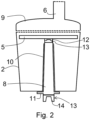
- the Figure 2 shows a schematic cross-section through a shredding attachment. It is shown that the collecting basket 2 has a guide 10 for the adapter 8 of the shaft that tapers conically towards the basket opening. The adapter 8 also tapers conically upwards towards the basket opening. The conical shape makes it easier to thread the adapter 8 into the guide 10.
- the adapter 8 has a stop 11 on its underside that can be shaped like a flange, for example. The stop 11 limits the insertion of the adapter 8 into the guide 10.
- the collecting basket 2 can have one or two handles at its upper end, for example. Handles at the upper end can protrude to the side.
- the two coupling elements 12 and 13 can be firmly connected to one another, for example by means of a locking connection, and thus to be connected to one another in a rotationally fixed manner in both directions of rotation.
- This embodiment is particularly advantageous when the result of the shredding can be changed by selecting the direction of rotation.
- the adapter can have a coupling element 13 with downwardly projecting arms 14 on its underside. Two arms 14 can grip a blade of the mixing tool in order to establish the rotationally fixed connection between the mixing tool and the adapter 8.
- the two arms 14 can be arranged as in Figure 2 shown taper towards the bottom to facilitate connection to a blade of a mixing tool.
- the coupling element 14 can also be designed differently on the bottom to connect the adapter 8 to the mixing tool in a rotationally fixed manner.
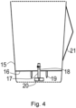
- FIG. 3 A sectional view is shown schematically how the collecting basket 2 and the other Figure 2 shown components can be inserted into a food preparation vessel 15.
- the food preparation vessel 15 comprises a base 16.
- a shaft 17 is passed through the base 16.
- a blade 18 is shown, which protrudes laterally from the shaft 17.
- the Figure 3 shows that the blade 18 has a tapered cutting edge and an opposite blunt edge. However, there is usually more than just one blade 17 protruding laterally from the shaft 17, for example four blades 18.
- An arm 14 can then reach between two blades 18 to create a rotationally fixed connection.
- Off-center means an arrangement that is at a distance from the axis of rotation around which the adapter 8 can be rotated.
- such blades 18 can protrude laterally from the shaft 17 and be arranged close to the bottom 16 as shown.
- the one or more blades 18 together with the shaft 17 form a mixing tool which mixes a food or one or more ingredients of a food at the bottom of the food preparation vessel 15 and thus at the base 16.
- One or more heating conductors can be integrated into the base 16.
- the underside of the base 16 can have electrical plugs 19 projecting downwards, via which the heating conductors can be supplied with power.
- the base 16 When the food preparation vessel 15 is in the upright position, the base 16 has the Figure 3 shown a distance from the underside.
- the base is connected to the outer surface of the food preparation vessel 15 accordingly. This makes it possible for the plugs 19 and the shaft 17 to protrude downwards from the base 16 without themselves coming into contact with a surface.
- the lower end of the shaft 17 can have a coupling element 20, which can be connected in a rotationally fixed manner to a matching coupling element of the shaft of the electric motor of the associated food preparation device.
- An axially fixed connection is not necessary and is also not desired in order to speed up the coupling.
- the food preparation vessel 15 can then be inserted into a receptacle of the remaining part of the food preparation device and can also be removed from it again.
- the shaft of the electric motor then extends into the receptacle from below a suitable distance, as do electrical sockets, which can be electrically connected to the plugs 19 by inserting the food preparation vessel into the receptacle.
- the food preparation vessel 15 can comprise a handle 21 projecting to the side.
- the collecting basket 2 does not comprise such a handle projecting to the side, since otherwise the collecting basket 2 could not be inserted into the food preparation vessel 15.
- the collecting basket 2 can have handles at its upper end which project out at the transition between the lid 9 and the food preparation vessel 15 when the lid 9 closes the collecting basket 2 and the collecting basket is inserted into the food preparation vessel 15.
- the food preparation vessel 15 is shown schematically Figure 3 shown, i.e. without the collecting basket inserted in it and the other Figure 2 shown components.
- the food preparation vessel 15 tapers slightly downwards so that it can be easily inserted into a receptacle of a base part.
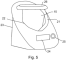
- a food preparation vessel 15 is shown which is inserted into a receptacle 22 of another part 23 of a food preparation device.
- the other part 23 is called the base part.
- the base part 23 comprises a touch-sensitive display 24 and a rotary control 25.
- the rotary control 25 can be used to set a speed for the mixing tool and thus also for the chopping tool.
- selected speeds or selected speed levels can be displayed via the display 24.
- the touch-sensitive display 24 can be set up to enter speeds or speed levels.
- the base part 23 contains a control unit, an electric motor, a shaft of the electric motor and a power supply for the heating conductors of the food preparation vessel 15.
- the base part 23 comprises an electrical plug which can supply the base part 23 with power via an electrical cable when the electrical plug is plugged into a suitable external electrical socket in a household.
- the food preparation vessel 15 can be closed with a lid 26 when the collecting basket is not inserted.
- the lid 26 can be locked by the base part 23 so that the lid 26 can then no longer be removed from the food preparation vessel 15.
- the lid 26 can be in two parts. For example, one part has a small opening that can be closed with the second part of the lid 26.
- the lid 26 can have a peripheral edge that ensures that liquid on the lid cannot flow outwards from the lid.
- the food preparation vessel 15 can be removed upwards from the holder 22.
- the food preparation vessel 15 and the collecting basket 2 can be so circular in section that the collecting basket 2 can be inserted into the food preparation vessel 15 without having to align the collecting basket 2.
- the collecting basket 2 is then reliably held by the food preparation vessel 15.
- the Figure 6 shows a top view of a mixing tool 27 with a total of four blades 18.
- the blades 18 protrude laterally from a shaft 17.
- arms 14 of a coupling element 13 shown in section extend between two blades 18 in each case so that a rotation of the mixing tool 27 is transmitted to the adapter 8 and thus to the shredding tool 4.
- Each blade 18 has a cutting edge 28 and a blunt opposite edge 29.
- a cutting edge 28 tapers to a point in section, which is not the case with the blunt edge 29. If the mixing tool is moved in the opposite direction to the cutting direction along the Figure 6 shown arrow, then at sufficiently low rotation speeds the food will not be chopped or will not be chopped to any significant extent.
Landscapes
- Engineering & Computer Science (AREA)
- Mechanical Engineering (AREA)
- Food Science & Technology (AREA)
- Food-Manufacturing Devices (AREA)
- Crushing And Pulverization Processes (AREA)
- Preparation Of Fruits And Vegetables (AREA)
Applications Claiming Priority (2)
| Application Number | Priority Date | Filing Date | Title |
|---|---|---|---|
| EP20184886.8A EP3936016A1 (fr) | 2020-07-09 | 2020-07-09 | Appareil de préparation des aliments destiné à la coupe des denrées alimentaires |
| EP21150396.6A EP4026460B8 (fr) | 2020-07-09 | 2021-01-06 | Appareil de préparation des aliments permettant de couper les aliments, pièce rapportée de broyage et procédé |
Related Parent Applications (2)
| Application Number | Title | Priority Date | Filing Date |
|---|---|---|---|
| EP21150396.6A Division EP4026460B8 (fr) | 2020-07-09 | 2021-01-06 | Appareil de préparation des aliments permettant de couper les aliments, pièce rapportée de broyage et procédé |
| EP21150396.6A Division-Into EP4026460B8 (fr) | 2020-07-09 | 2021-01-06 | Appareil de préparation des aliments permettant de couper les aliments, pièce rapportée de broyage et procédé |
Publications (3)
| Publication Number | Publication Date |
|---|---|
| EP4494536A2 true EP4494536A2 (fr) | 2025-01-22 |
| EP4494536A3 EP4494536A3 (fr) | 2025-04-02 |
| EP4494536B1 EP4494536B1 (fr) | 2026-03-25 |
Family
ID=78821715
Family Applications (3)
| Application Number | Title | Priority Date | Filing Date |
|---|---|---|---|
| EP24189943.4A Active EP4494536B1 (fr) | 2020-07-09 | 2021-01-06 | Appareil de préparation d'aliments pour couper des aliments, accessoire de broyage et procédé |
| EP23175746.9A Pending EP4233655A1 (fr) | 2020-07-09 | 2021-06-17 | Appareil de préparation des aliments permettant de couper les aliments, pièce rapportée de broyage et procédé |
| EP21180121.2A Active EP3936014B1 (fr) | 2020-07-09 | 2021-06-17 | Appareil de préparation des aliments permettant de couper les aliments, pièce rapportée de broyage et procédé |
Family Applications After (2)
| Application Number | Title | Priority Date | Filing Date |
|---|---|---|---|
| EP23175746.9A Pending EP4233655A1 (fr) | 2020-07-09 | 2021-06-17 | Appareil de préparation des aliments permettant de couper les aliments, pièce rapportée de broyage et procédé |
| EP21180121.2A Active EP3936014B1 (fr) | 2020-07-09 | 2021-06-17 | Appareil de préparation des aliments permettant de couper les aliments, pièce rapportée de broyage et procédé |
Country Status (4)
| Country | Link |
|---|---|
| EP (3) | EP4494536B1 (fr) |
| DE (1) | DE202021004229U1 (fr) |
| ES (1) | ES2948837T3 (fr) |
| PL (1) | PL3936014T3 (fr) |
Families Citing this family (2)
| Publication number | Priority date | Publication date | Assignee | Title |
|---|---|---|---|---|
| DE102022110290B4 (de) | 2022-04-27 | 2025-10-02 | Wundermix Gmbh | Küchenmaschinenanordnung |
| DE202022002722U1 (de) | 2022-04-27 | 2023-03-07 | Wundermix Gmbh | Küchenmaschinenanordnung und Zerkleinerungsbaugruppe für eine Küchenmaschine |
Citations (4)
| Publication number | Priority date | Publication date | Assignee | Title |
|---|---|---|---|---|
| EP2335534A1 (fr) | 2009-12-17 | 2011-06-22 | Koninklijke Philips Electronics N.V. | Râpe en forme de disque pour robot-mixeur |
| DE102010037769A1 (de) | 2010-09-24 | 2012-03-29 | Vorwerk & Co. Interholding Gmbh | Elektrisch betriebene Küchenmaschine sowie Verfahren zum Betreiben einer solchen Küchenmaschine |
| EP2636344A1 (fr) | 2012-03-09 | 2013-09-11 | Whirlpool Corporation | Robot de cuisine et ensemble de coupe réglable |
| WO2018007833A1 (fr) | 2016-07-08 | 2018-01-11 | Kenwood Limited | Robot culinaire |
Family Cites Families (12)
| Publication number | Priority date | Publication date | Assignee | Title |
|---|---|---|---|---|
| DE7507736U (de) | 1974-03-26 | 1975-07-03 | Moulinex Sa | Elektrohaushaltsgerät mit aufsetzbarem Zusatz |
| US4199122A (en) | 1978-07-10 | 1980-04-22 | Christie Eugene P | Support rack for polyethylene bag |
| US4194697A (en) | 1979-01-22 | 1980-03-25 | William Lembeck | Food processor and auxiliary mixing bowl therefor |
| DE102008013863A1 (de) | 2008-03-12 | 2009-09-17 | Vorwerk & Co. Interholding Gmbh | Eletromotorisch betriebene Küchenmaschine |
| FR2955475B1 (fr) * | 2010-01-22 | 2013-09-06 | Hameur Sa | Appareil multifonctionnel de traitement mecanique d'aliments |
| DE102012100940A1 (de) | 2012-02-06 | 2013-08-08 | Vorwerk & Co. Interholding Gmbh | Verfahren zum Zubereiten von Speisen in einem Gargefäß sowie Zusammenfassung von einem Gargefäß mit einem Obergefäß |
| DE202012105011U1 (de) * | 2012-12-21 | 2013-01-25 | Vorwerk & Co. Interholding Gmbh | Elektromotorisch betriebene Küchenmaschine |
| AT518073B1 (de) | 2016-03-25 | 2017-07-15 | Johann Innerhuber | Küchenmaschine |
| EP3586688A1 (fr) * | 2018-06-25 | 2020-01-01 | Koninklijke Philips N.V. | Appareil de préparation d'aliments |
| AT522365B1 (de) | 2019-05-13 | 2020-10-15 | Innerhuber Johann | Aufsatzbehalter fur eine Kiichenmaschine |
| EP4161332A4 (fr) * | 2020-07-17 | 2024-05-29 | Breville Pty Limited | Récipient de stockage pour robot culinaire |
| DE202020106270U1 (de) | 2020-11-02 | 2020-12-21 | Timo Plogstedt - Philip Bonmann GbR (vertretungsberechtigter Gesellschafter: Timo Plogstedt, 22767 Hamburg) | Saftpresse |
-
2021
- 2021-01-06 EP EP24189943.4A patent/EP4494536B1/fr active Active
- 2021-06-17 DE DE202021004229.6U patent/DE202021004229U1/de active Active
- 2021-06-17 EP EP23175746.9A patent/EP4233655A1/fr active Pending
- 2021-06-17 ES ES21180121T patent/ES2948837T3/es active Active
- 2021-06-17 EP EP21180121.2A patent/EP3936014B1/fr active Active
- 2021-06-17 PL PL21180121.2T patent/PL3936014T3/pl unknown
Patent Citations (4)
| Publication number | Priority date | Publication date | Assignee | Title |
|---|---|---|---|---|
| EP2335534A1 (fr) | 2009-12-17 | 2011-06-22 | Koninklijke Philips Electronics N.V. | Râpe en forme de disque pour robot-mixeur |
| DE102010037769A1 (de) | 2010-09-24 | 2012-03-29 | Vorwerk & Co. Interholding Gmbh | Elektrisch betriebene Küchenmaschine sowie Verfahren zum Betreiben einer solchen Küchenmaschine |
| EP2636344A1 (fr) | 2012-03-09 | 2013-09-11 | Whirlpool Corporation | Robot de cuisine et ensemble de coupe réglable |
| WO2018007833A1 (fr) | 2016-07-08 | 2018-01-11 | Kenwood Limited | Robot culinaire |
Also Published As
| Publication number | Publication date |
|---|---|
| EP4494536A3 (fr) | 2025-04-02 |
| ES2948837T3 (es) | 2023-09-20 |
| EP3936014A1 (fr) | 2022-01-12 |
| EP3936014B1 (fr) | 2023-05-31 |
| DE202021004229U1 (de) | 2023-04-18 |
| PL3936014T3 (pl) | 2023-09-25 |
| EP4494536B1 (fr) | 2026-03-25 |
| EP4233655A1 (fr) | 2023-08-30 |
Similar Documents
| Publication | Publication Date | Title |
|---|---|---|
| EP4026460B1 (fr) | Appareil de préparation des aliments permettant de couper les aliments, pièce rapportée de broyage et procédé | |
| EP0269793B1 (fr) | Appareil électroménager de traitement des aliments | |
| DE69825295T2 (de) | Küchen-mixer für umkehrbare drehrichtung | |
| DE2258841C3 (de) | Elektrische schneidemaschine fuer lebensmittel | |
| EP1304064B1 (fr) | Robot ménager pour la préparation d'aliments | |
| DE202021104380U1 (de) | Erweiterungs-Einsatz zur Aufnahme in einem Zubereitungsgefäß einer Küchenmaschine sowie Küchenmaschine mit dem Erweiterungs-Einsatz | |
| EP4494536B1 (fr) | Appareil de préparation d'aliments pour couper des aliments, accessoire de broyage et procédé | |
| EP4098155B1 (fr) | Insert d'extraction de jus pour un récipient de préparation, ainsi que robot de cuisine pourvu d'insert d'extraction de jus | |
| EP4101349B1 (fr) | Procédé d'épluchage de pommes de terre et robot de cuisine | |
| EP3886662B1 (fr) | Appareil de traitement d'aliments | |
| DE69913526T2 (de) | Eine drehvorrichtung für küchen-schneidmaschinen | |
| EP4119016B1 (fr) | Dispositif de préparation des aliments pourvu d'un accessoire en plusieurs parties | |
| AT503495B1 (de) | Vorrichtung zum zubereiten von getränken | |
| EP2845529B1 (fr) | Composante d'un appareil de cuisine | |
| DE202022104120U1 (de) | Schneidvorrichtung für ein Küchengerät | |
| EP4287917B1 (fr) | Agencement de robot culinaire | |
| EP4588409A1 (fr) | Appareil de cuisine avec coupe-spirale | |
| DE102021124947A1 (de) | Ergänzungsset für ein Multifunktionsküchengerät, ein Multifunktionsküchengerät und ein Verfahren zum Bearbeiten von Schneidgut | |
| DE4322280A1 (de) | Arbeitsbehälter für eine elektrisch betriebene Haushaltsküchenmaschine | |
| DE102012220996A1 (de) | Küchengerät | |
| EP3503777B1 (fr) | Disque de traitement pourvu de zones d'outil sélectionnables | |
| DE102022106265A1 (de) | Erweiterungs-Einsatz | |
| EP4119019A1 (fr) | Dispositif de coupe pour un broyage des denrées alimentaires et appareil de préparation des aliments | |
| WO2020216767A1 (fr) | Appareil de cuisine et accessoire pour l'étanchéification d'un couvercle de protection d'un appareil de cuisine | |
| CH393656A (de) | Motorisch angetriebene Küchenmaschine mit einem einen Elektromotor und Mittel zur Regulierung von dessen Drehzahl aufweisenden Grundteil sowie Zusatzgeräte, die an dem Grundteil angeschlossen werden können, insbesondere zum Zerkleinern und Mischen von Nahrungsmitteln, zum Schneiden von Salat, Raffeln von Gemüse, zur Saftzubereitung aus Früchten und Gemüsen und zum Auspressen von Zitrusfrüchten sowie zur Zubereitung von Teigen |
Legal Events
| Date | Code | Title | Description |
|---|---|---|---|
| STAA | Information on the status of an ep patent application or granted ep patent |
Free format text: STATUS: UNKNOWN |
|
| PUAI | Public reference made under article 153(3) epc to a published international application that has entered the european phase |
Free format text: ORIGINAL CODE: 0009012 |
|
| STAA | Information on the status of an ep patent application or granted ep patent |
Free format text: STATUS: THE APPLICATION HAS BEEN PUBLISHED |
|
| AC | Divisional application: reference to earlier application |
Ref document number: 4026460 Country of ref document: EP Kind code of ref document: P |
|
| AK | Designated contracting states |
Kind code of ref document: A2 Designated state(s): AL AT BE BG CH CY CZ DE DK EE ES FI FR GB GR HR HU IE IS IT LI LT LU LV MC MK MT NL NO PL PT RO RS SE SI SK SM TR |
|
| REG | Reference to a national code |
Ref country code: DE Free format text: PREVIOUS MAIN CLASS: A47J0043250000 Ipc: A47J0043070000 Ref country code: DE Ref legal event code: R079 Ref document number: 502021010150 Country of ref document: DE Free format text: PREVIOUS MAIN CLASS: A47J0043250000 Ipc: A47J0043070000 |
|
| PUAL | Search report despatched |
Free format text: ORIGINAL CODE: 0009013 |
|
| AK | Designated contracting states |
Kind code of ref document: A3 Designated state(s): AL AT BE BG CH CY CZ DE DK EE ES FI FR GB GR HR HU IE IS IT LI LT LU LV MC MK MT NL NO PL PT RO RS SE SI SK SM TR |
|
| RIC1 | Information provided on ipc code assigned before grant |
Ipc: A47J 43/06 20060101ALI20250225BHEP Ipc: A47J 43/046 20060101ALI20250225BHEP Ipc: A47J 43/07 20060101AFI20250225BHEP |
|
| STAA | Information on the status of an ep patent application or granted ep patent |
Free format text: STATUS: REQUEST FOR EXAMINATION WAS MADE |
|
| 17P | Request for examination filed |
Effective date: 20250918 |
|
| GRAP | Despatch of communication of intention to grant a patent |
Free format text: ORIGINAL CODE: EPIDOSNIGR1 |
|
| STAA | Information on the status of an ep patent application or granted ep patent |
Free format text: STATUS: GRANT OF PATENT IS INTENDED |
|
| INTG | Intention to grant announced |
Effective date: 20251218 |
|
| RAP3 | Party data changed (applicant data changed or rights of an application transferred) |
Owner name: VORWERK & CO. INTERHOLDING GMBH |
|
| GRAS | Grant fee paid |
Free format text: ORIGINAL CODE: EPIDOSNIGR3 |
|
| GRAA | (expected) grant |
Free format text: ORIGINAL CODE: 0009210 |
|
| STAA | Information on the status of an ep patent application or granted ep patent |
Free format text: STATUS: THE PATENT HAS BEEN GRANTED |
|
| AC | Divisional application: reference to earlier application |
Ref document number: 4026460 Country of ref document: EP Kind code of ref document: P |
|
| AK | Designated contracting states |
Kind code of ref document: B1 Designated state(s): AL AT BE BG CH CY CZ DE DK EE ES FI FR GB GR HR HU IE IS IT LI LT LU LV MC MK MT NL NO PL PT RO RS SE SI SK SM TR |
|
| REG | Reference to a national code |
Ref country code: CH Ref legal event code: F10 Free format text: ST27 STATUS EVENT CODE: U-0-0-F10-F00 (AS PROVIDED BY THE NATIONAL OFFICE) Effective date: 20260325 Ref country code: GB Ref legal event code: FG4D Free format text: NOT ENGLISH |
|
| REG | Reference to a national code |
Ref country code: CH Ref legal event code: R17 Free format text: ST27 STATUS EVENT CODE: U-0-0-R10-R17 (AS PROVIDED BY THE NATIONAL OFFICE) Effective date: 20260401 |
|
| REG | Reference to a national code |
Ref country code: DE Ref legal event code: R096 Ref document number: 502021010150 Country of ref document: DE |
|
| REG | Reference to a national code |
Ref country code: IE Ref legal event code: FG4D Free format text: LANGUAGE OF EP DOCUMENT: GERMAN |