EP4497877A1 - Système de changement rapide - Google Patents
Système de changement rapide Download PDFInfo
- Publication number
- EP4497877A1 EP4497877A1 EP24169201.1A EP24169201A EP4497877A1 EP 4497877 A1 EP4497877 A1 EP 4497877A1 EP 24169201 A EP24169201 A EP 24169201A EP 4497877 A1 EP4497877 A1 EP 4497877A1
- Authority
- EP
- European Patent Office
- Prior art keywords
- gripper
- quick
- change system
- drive
- elements
- Prior art date
- Legal status (The legal status is an assumption and is not a legal conclusion. Google has not performed a legal analysis and makes no representation as to the accuracy of the status listed.)
- Pending
Links
Images


Classifications
-
- E—FIXED CONSTRUCTIONS
- E02—HYDRAULIC ENGINEERING; FOUNDATIONS; SOIL SHIFTING
- E02F—DREDGING; SOIL-SHIFTING
- E02F3/00—Dredgers; Soil-shifting machines
- E02F3/04—Dredgers; Soil-shifting machines mechanically-driven
- E02F3/28—Dredgers; Soil-shifting machines mechanically-driven with digging tools mounted on a dipper- or bucket-arm, i.e. there is either one arm or a pair of arms, e.g. dippers, buckets
- E02F3/36—Component parts
- E02F3/3604—Devices to connect tools to arms, booms or the like
- E02F3/3677—Devices to connect tools to arms, booms or the like allowing movement, e.g. rotation or translation, of the tool around or along another axis as the movement implied by the boom or arms, e.g. for tilting buckets
- E02F3/3681—Rotators
-
- E—FIXED CONSTRUCTIONS
- E02—HYDRAULIC ENGINEERING; FOUNDATIONS; SOIL SHIFTING
- E02F—DREDGING; SOIL-SHIFTING
- E02F3/00—Dredgers; Soil-shifting machines
- E02F3/04—Dredgers; Soil-shifting machines mechanically-driven
- E02F3/28—Dredgers; Soil-shifting machines mechanically-driven with digging tools mounted on a dipper- or bucket-arm, i.e. there is either one arm or a pair of arms, e.g. dippers, buckets
- E02F3/36—Component parts
- E02F3/40—Dippers; Buckets ; Grab devices, e.g. manufacturing processes for buckets, form, geometry or material of buckets
- E02F3/413—Dippers; Buckets ; Grab devices, e.g. manufacturing processes for buckets, form, geometry or material of buckets with grabbing device
- E02F3/4135—Dippers; Buckets ; Grab devices, e.g. manufacturing processes for buckets, form, geometry or material of buckets with grabbing device with grabs mounted directly on a boom
-
- E—FIXED CONSTRUCTIONS
- E02—HYDRAULIC ENGINEERING; FOUNDATIONS; SOIL SHIFTING
- E02F—DREDGING; SOIL-SHIFTING
- E02F3/00—Dredgers; Soil-shifting machines
- E02F3/04—Dredgers; Soil-shifting machines mechanically-driven
- E02F3/96—Dredgers; Soil-shifting machines mechanically-driven with arrangements for alternate or simultaneous use of different digging elements
- E02F3/961—Dredgers; Soil-shifting machines mechanically-driven with arrangements for alternate or simultaneous use of different digging elements with several digging elements or tools mounted on one machine
-
- B—PERFORMING OPERATIONS; TRANSPORTING
- B66—HOISTING; LIFTING; HAULING
- B66C—CRANES; LOAD-ENGAGING ELEMENTS OR DEVICES FOR CRANES, CAPSTANS, WINCHES, OR TACKLES
- B66C1/00—Load-engaging elements or devices attached to lifting or lowering gear of cranes or adapted for connection therewith for transmitting lifting forces to articles or groups of articles
- B66C1/10—Load-engaging elements or devices attached to lifting or lowering gear of cranes or adapted for connection therewith for transmitting lifting forces to articles or groups of articles by mechanical means
- B66C1/42—Gripping members engaging only the external or internal surfaces of the articles
- B66C1/425—Gripping members engaging only the external or internal surfaces of the articles motor actuated
- B66C1/427—Gripping members engaging only the external or internal surfaces of the articles motor actuated by hydraulic or pneumatic motors
-
- B—PERFORMING OPERATIONS; TRANSPORTING
- B66—HOISTING; LIFTING; HAULING
- B66C—CRANES; LOAD-ENGAGING ELEMENTS OR DEVICES FOR CRANES, CAPSTANS, WINCHES, OR TACKLES
- B66C1/00—Load-engaging elements or devices attached to lifting or lowering gear of cranes or adapted for connection therewith for transmitting lifting forces to articles or groups of articles
- B66C1/10—Load-engaging elements or devices attached to lifting or lowering gear of cranes or adapted for connection therewith for transmitting lifting forces to articles or groups of articles by mechanical means
- B66C1/42—Gripping members engaging only the external or internal surfaces of the articles
- B66C1/44—Gripping members engaging only the external or internal surfaces of the articles and applying frictional forces
-
- E—FIXED CONSTRUCTIONS
- E02—HYDRAULIC ENGINEERING; FOUNDATIONS; SOIL SHIFTING
- E02F—DREDGING; SOIL-SHIFTING
- E02F3/00—Dredgers; Soil-shifting machines
- E02F3/04—Dredgers; Soil-shifting machines mechanically-driven
- E02F3/28—Dredgers; Soil-shifting machines mechanically-driven with digging tools mounted on a dipper- or bucket-arm, i.e. there is either one arm or a pair of arms, e.g. dippers, buckets
- E02F3/36—Component parts
-
- E—FIXED CONSTRUCTIONS
- E02—HYDRAULIC ENGINEERING; FOUNDATIONS; SOIL SHIFTING
- E02F—DREDGING; SOIL-SHIFTING
- E02F3/00—Dredgers; Soil-shifting machines
- E02F3/04—Dredgers; Soil-shifting machines mechanically-driven
- E02F3/28—Dredgers; Soil-shifting machines mechanically-driven with digging tools mounted on a dipper- or bucket-arm, i.e. there is either one arm or a pair of arms, e.g. dippers, buckets
- E02F3/36—Component parts
- E02F3/3604—Devices to connect tools to arms, booms or the like
- E02F3/3609—Devices to connect tools to arms, booms or the like of the quick acting type, e.g. controlled from the operator seat
- E02F3/3636—Devices to connect tools to arms, booms or the like of the quick acting type, e.g. controlled from the operator seat using two or four movable transversal pins
-
- E—FIXED CONSTRUCTIONS
- E02—HYDRAULIC ENGINEERING; FOUNDATIONS; SOIL SHIFTING
- E02F—DREDGING; SOIL-SHIFTING
- E02F3/00—Dredgers; Soil-shifting machines
- E02F3/04—Dredgers; Soil-shifting machines mechanically-driven
- E02F3/28—Dredgers; Soil-shifting machines mechanically-driven with digging tools mounted on a dipper- or bucket-arm, i.e. there is either one arm or a pair of arms, e.g. dippers, buckets
- E02F3/36—Component parts
- E02F3/40—Dippers; Buckets ; Grab devices, e.g. manufacturing processes for buckets, form, geometry or material of buckets
- E02F3/402—Dippers; Buckets ; Grab devices, e.g. manufacturing processes for buckets, form, geometry or material of buckets with means for facilitating the loading thereof, e.g. conveyors
- E02F3/404—Dippers; Buckets ; Grab devices, e.g. manufacturing processes for buckets, form, geometry or material of buckets with means for facilitating the loading thereof, e.g. conveyors comprising two parts movable relative to each other, e.g. for gripping
-
- E—FIXED CONSTRUCTIONS
- E02—HYDRAULIC ENGINEERING; FOUNDATIONS; SOIL SHIFTING
- E02F—DREDGING; SOIL-SHIFTING
- E02F3/00—Dredgers; Soil-shifting machines
- E02F3/04—Dredgers; Soil-shifting machines mechanically-driven
- E02F3/96—Dredgers; Soil-shifting machines mechanically-driven with arrangements for alternate or simultaneous use of different digging elements
- E02F3/963—Arrangements on backhoes for alternate use of different tools
Definitions
- the invention relates to a quick-change system for changing attachments on a construction machine according to the preamble of claim 1.
- Such quick-change systems are used on excavators or other similar construction machines between an attachment of the construction machine and the tool as a rotary-swivel unit to expand the range of movement.
- Such quick-change systems usually contain a quick-changer which is arranged on a connecting part and can be rotated about a rotary axis by means of a hydraulic rotary drive and can be pivoted about a pivot axis orthogonal to the rotary axis by means of a hydraulic pivot drive, which has mounts and at least one locking element for releasably holding an attachment coupled to the quick-changer.
- the attachments coupled to the quick-changer such as swivel buckets, grapples, shears, compactors, magnets, hydraulic hammers or the like, can be rotated not only about a pivot axis arranged transversely to the longitudinal axis of an excavator boom, but also about a pivot axis orthogonal to this pivot axis. From the DE 10 2020 127 313 B3 Such a quick-change system is known.
- the object of the invention is to create a quick-change system of the type mentioned above, which enables an expanded range of applications.
- the quick-change system according to the invention for changing attachments on a construction machine contains a quick-change device arranged on a carrier so that it can rotate about a rotation axis by means of a rotary drive and/or pivot about a pivot axis by means of a swivel drive for coupling a tool or attachment.
- a gripper arrangement that can be operated by means of a gripper drive and can be easily retrofitted if necessary is attached to the quick-change device. with several gripper arms that can move against each other. This means that pipes, rings, rods, stones or similar can be gripped and transported.
- exchangeable gripper elements are arranged on the gripper arms. This makes it easy to expand the area of application. In order to adapt to different requirements and areas of application, the entire gripper arrangement does not have to be rebuilt and changed. Only the gripper elements arranged separately on the gripper arms have to be replaced.
- the quick changer with the gripper arrangement arranged thereon is arranged on the carrier so that it can rotate about the rotation axis by means of the rotary drive and can pivot about the pivot axis orthogonal to the rotation axis by means of the swivel drive.
- the quick changer can also be arranged on the carrier so that it can only rotate or tilt.
- the gripper arrangement preferably has two gripper arms arranged on a support structure so that they can pivot relative to one another.
- the gripper arrangement can also contain more than two gripper arms.
- the gripper elements which are individually tailored to the desired application area, can be attached to the gripper arms via a non-destructively detachable connection. This means that the gripper elements can be exchanged or replaced particularly quickly and without major conversion work.
- the gripper elements can also be welded to the gripper arms or fixed to the gripper arms in another suitable way. Even then, the gripper elements can be exchanged, albeit with a little more effort. The entire gripper arm does not have to be replaced to adapt it to a specific application area.
- the gripper elements have an outer clamping surface for gripping components from the inside.
- the gripper elements can also contain an outwardly protruding attachment with a stop surface.
- elastic pressure bodies can be arranged on the gripper elements. This can be used to grip, for example, sensitive components made of marble or the like.
- the gripper drive can contain a first gripper cylinder for driving a first gripper arm and a second gripper cylinder for driving a second gripper arm.
- the gripper drive can also be designed differently.
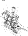
- a quick-change system 1 also referred to as a tiltrotator, is shown for changing attachments on an excavator or a similar construction machine.
- the quick-change system 1 contains a quick-change device 3 which is arranged on a carrier 2 so that it can rotate and swivel by means of a rotary and swivel drive and which is designed for the automatic or manual coupling of attachments.
- the quick-change device 3 is mounted on the carrier 2, which can be coupled either directly or via a hydraulically operated quick-change device to an excavator boom or another attachment element of a construction machine, by means of a hydraulic rotary drive 4.
- the rotation axis 5 can be rotated by 360° and can be pivoted about a pivot axis 7 orthogonal to the rotation axis 5 by means of a hydraulic pivot drive 6.
- the quick-change system designed here as a tiltrotator, contains a drive housing 8 in which the quick coupler 3 is mounted so that it can rotate 360° about the rotation axis 5, which is aligned vertically here.
- the drive housing 8 there is also a hydraulic rotary feedthrough (not visible here) with a stator arranged in the drive housing 8 so that it cannot rotate relative to it and a rotor rotatably mounted within the stator for supplying a hydraulic fluid to the quick coupler 3.
- the rotary drive 4 contains a hydraulic motor 9 designed as a hydraulic drive, by means of which the quick coupler 3 can be rotated by a motor through 360° about the rotation axis 5 relative to the drive housing 8 via a gear with a worm wheel arranged within the drive housing 8 and a drive worm rotatable by the hydraulic motor 9.
- the drive housing 8 is arranged on the carrier 2 via laterally projecting bearing pins 10 within two spaced-apart bearing eyes 11 so as to be pivotable about the pivot axis 7 orthogonal to the axis of rotation 5 and can be pivoted relative to the connecting part 1 about the pivot axis 6 relative to the axis of rotation 5 via the hydraulic pivot drive 6.
- Figure 1 and 2 shown position by approximately +/- 45°.
- the excavator attachment 1 which is designed here as a tiltrotator, allows the attachments coupled to the quick coupler 3 not only to be rotated about the axis of rotation 5, but also to be tilted relative to the carrier 2 about the pivot axis 7 that is orthogonal to the axis of rotation 5, thereby expanding the movement options and thereby increasing the area of application.
- the quick-change system 1 can also be designed just to rotate or pivot the quick coupler 3.
- the carrier 2 has two side cheeks 12 parallel to one another as well as front and rear cross pieces 13 with the bearing eyes 11 arranged thereon.
- the drive housing 8 is pivotally mounted about the pivot axis 7 via the two bearing pins 10 in the bearing eyes 11 of the front and rear cross pieces 13.
- four openings 14 for receiving two parallel bolt-shaped connecting elements are provided in the connection part 1 shown.
- the quick coupler 3 which is designed for coupling an attachment or tool and can be operated manually or hydraulically, contains a housing 15 which has first receptacles 16 open on one side for receiving and holding a first bolt-shaped coupling element on the tool side and second receptacles on the other side - not visible here - for receiving and holding a second bolt-shaped coupling element on the tool side.
- An embodiment of a hydraulically operated quick coupler 3 for automatically coupling a tool is shown in the DE 10 2018 128 479 A1
- the quick coupler 3 can also be designed as a manually operated quick coupler.
- An embodiment of a manually operated quick coupler is e.g. in the DE 20 2017 001 992 U1 revealed.
- the swivel drive 6 is formed by two double-acting actuating cylinders 17 and 18, each with a cylinder housing 19 attached to the respective side wall 12 of the carrier 2 and a piston rod 20 that is slidably arranged in the cylinder housing 19 and can be moved hydraulically.
- the free ends of the piston rods 20 are connected to the drive housing 8 via a joint eye 21 and a corresponding holder 22.
- the swivel drive 6 can also be formed by a hydraulic motor or another suitable hydraulic drive.
- a gripper arrangement 23 with two gripper arms 24 and 25 that can be pivoted against each other.
- the two gripper arms 24 and 25 are also attached to a Figure 2 shown support structure 26 are arranged so as to be pivotable about an axis 27 or 28 and can be folded out or in by means of a hydraulic gripper drive formed here by two double-acting gripper cylinders 29 or 30.
- One of the two gripper arms 24 and 25 has a slot-shaped recess 31 for receiving the other gripper arm 5.
- the two gripper arms 24 and 25, which can be pivoted by a gripper cylinder 29 or 30, can be moved into one another when folded in and can be folded in completely.
- the gripper arm 24 provided with the slot-shaped recess 31 is arranged on the left side of the support structure 26
- the gripper arm 24 provided with the slot-shaped recess 31 is in the execution of Figure 2 on the right side of the support structure 26.
- the support structure 26 is symmetrical so that it can easily be mounted on the quick coupler 3 in two different positions, ie rotated by 180°.
- separate exchangeable gripper elements 32 are arranged on the two gripper arms 24 and 25.
- the gripper elements 32 are attached to the gripper arms 24 and 25 via screws 33 or another non-destructively detachable connection. While two gripper elements 32 are attached to the gripper arm 24 provided with the slot-shaped recess 31, one above and one below the recess 31, only one gripper element 32 is attached to the other gripper arm 25.
- the in Figure 1 and 2 The gripper elements 32 shown are designed for gripping shaft rings, pipes or the like. As can be seen particularly from the enlarged illustration of the Figures 4 and 5 As can be seen, these gripper elements 32 have a straight outer clamping surface 34 and an outwardly projecting nose-shaped projection 35 with a stop surface 36. By moving the two gripper arms 24 and 25 apart, shaft pipes or other parts can be clamped from the inside and held for transport via the mutually parallel clamping surfaces 34 of the two gripper elements 32.
- the gripper elements 32 are detachably attached to the gripper arms via screws 33 and can thus be easily replaced or exchanged.
- the gripper elements 32 can also be welded to the gripper arms or fixed to the gripper arms in another suitable manner, as shown in Figure 5
- the gripper elements 32 can then also be exchanged or changed to adapt to a different requirement. However, the change then involves greater effort.
- gripper elements 32 In addition to the gripper elements 32 shown, other gripper elements adapted to a specific application area can of course also be attached to the gripper arms 24 and 25.
- gripper elements 38 provided with rubber buffers or other elastic pressure bodies 37 are attached to the gripper arms 24 and 25 This can be used to grip sensitive components made of marble or similar.
- Other specially adapted gripper elements can also be installed quickly and easily.
Landscapes
- Engineering & Computer Science (AREA)
- Mechanical Engineering (AREA)
- Mining & Mineral Resources (AREA)
- Civil Engineering (AREA)
- General Engineering & Computer Science (AREA)
- Structural Engineering (AREA)
- Earth Drilling (AREA)
- Shovels (AREA)
Applications Claiming Priority (1)
| Application Number | Priority Date | Filing Date | Title |
|---|---|---|---|
| DE102023119932.3A DE102023119932A1 (de) | 2023-07-27 | 2023-07-27 | Schnellwechselsystem |
Publications (1)
| Publication Number | Publication Date |
|---|---|
| EP4497877A1 true EP4497877A1 (fr) | 2025-01-29 |
Family
ID=90719790
Family Applications (1)
| Application Number | Title | Priority Date | Filing Date |
|---|---|---|---|
| EP24169201.1A Pending EP4497877A1 (fr) | 2023-07-27 | 2024-04-09 | Système de changement rapide |
Country Status (7)
| Country | Link |
|---|---|
| US (1) | US20250034833A1 (fr) |
| EP (1) | EP4497877A1 (fr) |
| JP (1) | JP2025018953A (fr) |
| CN (1) | CN119373179A (fr) |
| AU (1) | AU2024205065A1 (fr) |
| CA (1) | CA3236162A1 (fr) |
| DE (1) | DE102023119932A1 (fr) |
Citations (11)
| Publication number | Priority date | Publication date | Assignee | Title |
|---|---|---|---|---|
| US4542929A (en) * | 1983-09-01 | 1985-09-24 | Possinger Warren K | Articulating clam type grapple for a backhoe |
| EP1632450A2 (fr) * | 2004-09-06 | 2006-03-08 | Liebherr-Hydraulikbagger GmbH | Outil d'excavation ou de préhension |
| WO2007097698A1 (fr) * | 2006-02-26 | 2007-08-30 | Indexator Ab | Arrangement relatif a un dispositif rotatif |
| DE202015102886U1 (de) * | 2015-06-03 | 2015-07-01 | Dms Technologie Gmbh | Greifaufsatz für Hebewerkzeug |
| US20180135275A1 (en) * | 2016-11-15 | 2018-05-17 | Ryan Arnold Bremner | Grapple tip device and method |
| DE202017001992U1 (de) | 2017-03-08 | 2018-06-11 | Kinshofer Gmbh | Schnellkuppler |
| EP3517691A1 (fr) * | 2018-01-26 | 2019-07-31 | DMS Technologie GmbH | Hausse de préhension pour organes de préhension d'un préhenseur |
| DE102018128479A1 (de) | 2018-11-14 | 2020-05-14 | Oilquick Deutschland Gmbh | Schnellwechsler und Schnellwechselsystem mit einem derartigen Schnellwechsler |
| KR20210022392A (ko) * | 2019-08-20 | 2021-03-03 | 강윤창 | 효율적인 작업이 가능한 굴삭기용 장치 |
| DE102020127313B3 (de) | 2020-10-16 | 2022-02-03 | OilQuick Deutschland KG | Schnellwechselsystem zum Wechseln von Anbaugeräten an einer Baumaschine |
| EP4134346A1 (fr) * | 2021-07-23 | 2023-02-15 | Kinshofer GmbH | Entraînement pivotant hydraulique pour un préhenseur |
Family Cites Families (9)
| Publication number | Priority date | Publication date | Assignee | Title |
|---|---|---|---|---|
| JPH0313359U (fr) * | 1989-06-27 | 1991-02-12 | ||
| JP2584686Y2 (ja) * | 1991-11-28 | 1998-11-05 | マツダアステック株式会社 | 建設機械の運搬物把持装置 |
| JPH08165673A (ja) * | 1994-12-16 | 1996-06-25 | Mitsubishi Heavy Ind Ltd | 産業機械 |
| JP2000086146A (ja) * | 1998-09-04 | 2000-03-28 | Eagle Kuranpu Kk | コンクリート内吊り用クランプ |
| DE102005040537A1 (de) * | 2004-09-06 | 2006-06-08 | Liebherr-Hydraulikbagger Gmbh | Grab- oder Greifwerkzeug |
| JP5518632B2 (ja) * | 2010-08-23 | 2014-06-11 | 日立建機株式会社 | グラップル爪の溶接構造とポイント部の交換方法 |
| SE536584C2 (sv) * | 2012-05-22 | 2014-03-11 | Smp Parts Ab | Klipptillsatsenhet till en grävmaskin eller ett traktorgrävmaskinsaggregat |
| JP7193123B2 (ja) * | 2018-10-22 | 2022-12-20 | 鈴健興業株式会社 | グラップル及びバックホウ |
| JP7673546B2 (ja) * | 2020-12-09 | 2025-05-09 | コベルコ建機株式会社 | 保持装置 |
-
2023
- 2023-07-27 DE DE102023119932.3A patent/DE102023119932A1/de active Pending
-
2024
- 2024-04-09 EP EP24169201.1A patent/EP4497877A1/fr active Pending
- 2024-04-17 CA CA3236162A patent/CA3236162A1/en active Pending
- 2024-06-27 CN CN202410847009.XA patent/CN119373179A/zh active Pending
- 2024-06-27 JP JP2024103512A patent/JP2025018953A/ja active Pending
- 2024-07-22 US US18/779,514 patent/US20250034833A1/en active Pending
- 2024-07-24 AU AU2024205065A patent/AU2024205065A1/en active Pending
Patent Citations (11)
| Publication number | Priority date | Publication date | Assignee | Title |
|---|---|---|---|---|
| US4542929A (en) * | 1983-09-01 | 1985-09-24 | Possinger Warren K | Articulating clam type grapple for a backhoe |
| EP1632450A2 (fr) * | 2004-09-06 | 2006-03-08 | Liebherr-Hydraulikbagger GmbH | Outil d'excavation ou de préhension |
| WO2007097698A1 (fr) * | 2006-02-26 | 2007-08-30 | Indexator Ab | Arrangement relatif a un dispositif rotatif |
| DE202015102886U1 (de) * | 2015-06-03 | 2015-07-01 | Dms Technologie Gmbh | Greifaufsatz für Hebewerkzeug |
| US20180135275A1 (en) * | 2016-11-15 | 2018-05-17 | Ryan Arnold Bremner | Grapple tip device and method |
| DE202017001992U1 (de) | 2017-03-08 | 2018-06-11 | Kinshofer Gmbh | Schnellkuppler |
| EP3517691A1 (fr) * | 2018-01-26 | 2019-07-31 | DMS Technologie GmbH | Hausse de préhension pour organes de préhension d'un préhenseur |
| DE102018128479A1 (de) | 2018-11-14 | 2020-05-14 | Oilquick Deutschland Gmbh | Schnellwechsler und Schnellwechselsystem mit einem derartigen Schnellwechsler |
| KR20210022392A (ko) * | 2019-08-20 | 2021-03-03 | 강윤창 | 효율적인 작업이 가능한 굴삭기용 장치 |
| DE102020127313B3 (de) | 2020-10-16 | 2022-02-03 | OilQuick Deutschland KG | Schnellwechselsystem zum Wechseln von Anbaugeräten an einer Baumaschine |
| EP4134346A1 (fr) * | 2021-07-23 | 2023-02-15 | Kinshofer GmbH | Entraînement pivotant hydraulique pour un préhenseur |
Also Published As
| Publication number | Publication date |
|---|---|
| AU2024205065A1 (en) | 2025-02-13 |
| CA3236162A1 (en) | 2025-06-11 |
| CN119373179A (zh) | 2025-01-28 |
| US20250034833A1 (en) | 2025-01-30 |
| DE102023119932A1 (de) | 2025-01-30 |
| JP2025018953A (ja) | 2025-02-06 |
Similar Documents
| Publication | Publication Date | Title |
|---|---|---|
| DE69217367T2 (de) | Baggerlöffelbetätigungsorgan mit schnellkupplungvorrichtung | |
| DE60034062T2 (de) | Hydraulisches sammelwerkzeug | |
| EP3985175A1 (fr) | Système de changement rapide permettant de changer les accessoires sur une machine de construction | |
| EP0296367A2 (fr) | Dispositif automatique de changement d'outil | |
| DE202008008446U1 (de) | Werkzeug zum Aufschrauben eines Kolbens auf der Kolbenstange eines Hydraulikzylinders und Hydraulikzylinder | |
| EP3875692A1 (fr) | Système de changement rapide pour un engin de construction | |
| EP2787125B1 (fr) | Dispositif d'accouplement pour un accessoire de machine d'excavation | |
| DE69305678T3 (de) | Verfahren und Vorrichtung zum Handhaben von Rohren für eine Gesteinbohrmaschine | |
| DE69001771T2 (de) | Anordnung zur Handhabung von Bohrstangen in einem Gesteinsbohraggregat oder dgl. | |
| EP0168711B1 (fr) | Dispositif de préhension | |
| EP4263407B1 (fr) | Support d'enrouleur de câble pour supporter en rotation un enrouleur de câble | |
| EP4471216A1 (fr) | Tiltrotateur | |
| EP4502278A1 (fr) | Système de changement rapide | |
| EP4497877A1 (fr) | Système de changement rapide | |
| DE202023104217U1 (de) | Schnellwechselsystem | |
| EP3874094B1 (fr) | Dispositif pour la conduite de fluide hydraulique | |
| AT521315B1 (de) | Winkelstück und Hebevorrichtung | |
| EP0728874A2 (fr) | Benne preneuse à deux coquilles | |
| DE19806057A1 (de) | Baumaschinenadapter | |
| DE3246002C2 (fr) | ||
| EP0625613B1 (fr) | Dispositif d'attelage pour attacher un outil au bras d'une excavatrice | |
| EP0218899B1 (fr) | Ciseaux de démolition | |
| DE29621253U1 (de) | Schwenkadapter | |
| DE29601727U1 (de) | Werkzeugwechselvorrichtung für Hydraulikbagger | |
| DE102016014905B3 (de) | Werkzeugadapter mit einer Vorrichtung zur Verriegelungskontrolle einer Schnellwechselvorrichtung für Baugeräte |
Legal Events
| Date | Code | Title | Description |
|---|---|---|---|
| PUAI | Public reference made under article 153(3) epc to a published international application that has entered the european phase |
Free format text: ORIGINAL CODE: 0009012 |
|
| STAA | Information on the status of an ep patent application or granted ep patent |
Free format text: STATUS: THE APPLICATION HAS BEEN PUBLISHED |
|
| AK | Designated contracting states |
Kind code of ref document: A1 Designated state(s): AL AT BE BG CH CY CZ DE DK EE ES FI FR GB GR HR HU IE IS IT LI LT LU LV MC ME MK MT NL NO PL PT RO RS SE SI SK SM TR |
|
| STAA | Information on the status of an ep patent application or granted ep patent |
Free format text: STATUS: REQUEST FOR EXAMINATION WAS MADE |
|
| 17P | Request for examination filed |
Effective date: 20250729 |