EP4506536A1 - Pompe à vide à spirales et système de pompe à vide à spirales - Google Patents
Pompe à vide à spirales et système de pompe à vide à spirales Download PDFInfo
- Publication number
- EP4506536A1 EP4506536A1 EP24197612.5A EP24197612A EP4506536A1 EP 4506536 A1 EP4506536 A1 EP 4506536A1 EP 24197612 A EP24197612 A EP 24197612A EP 4506536 A1 EP4506536 A1 EP 4506536A1
- Authority
- EP
- European Patent Office
- Prior art keywords
- spiral
- vacuum pump
- scroll vacuum
- drive shaft
- carrier
- Prior art date
- Legal status (The legal status is an assumption and is not a legal conclusion. Google has not performed a legal analysis and makes no representation as to the accuracy of the status listed.)
- Granted
Links
Images


Classifications
-
- F—MECHANICAL ENGINEERING; LIGHTING; HEATING; WEAPONS; BLASTING
- F04—POSITIVE - DISPLACEMENT MACHINES FOR LIQUIDS; PUMPS FOR LIQUIDS OR ELASTIC FLUIDS
- F04C—ROTARY-PISTON, OR OSCILLATING-PISTON, POSITIVE-DISPLACEMENT MACHINES FOR LIQUIDS; ROTARY-PISTON, OR OSCILLATING-PISTON, POSITIVE-DISPLACEMENT PUMPS
- F04C18/00—Rotary-piston pumps specially adapted for elastic fluids
- F04C18/02—Rotary-piston pumps specially adapted for elastic fluids of arcuate-engagement type, i.e. with circular translatory movement of co-operating members, each member having the same number of teeth or tooth-equivalents
- F04C18/0207—Rotary-piston pumps specially adapted for elastic fluids of arcuate-engagement type, i.e. with circular translatory movement of co-operating members, each member having the same number of teeth or tooth-equivalents both members having co-operating elements in spiral form
- F04C18/0215—Rotary-piston pumps specially adapted for elastic fluids of arcuate-engagement type, i.e. with circular translatory movement of co-operating members, each member having the same number of teeth or tooth-equivalents both members having co-operating elements in spiral form where only one member is moving
-
- F—MECHANICAL ENGINEERING; LIGHTING; HEATING; WEAPONS; BLASTING
- F01—MACHINES OR ENGINES IN GENERAL; ENGINE PLANTS IN GENERAL; STEAM ENGINES
- F01C—ROTARY-PISTON OR OSCILLATING-PISTON MACHINES OR ENGINES
- F01C21/00—Component parts, details or accessories not provided for in groups F01C1/00 - F01C20/00
- F01C21/02—Arrangements of bearings
-
- F—MECHANICAL ENGINEERING; LIGHTING; HEATING; WEAPONS; BLASTING
- F04—POSITIVE - DISPLACEMENT MACHINES FOR LIQUIDS; PUMPS FOR LIQUIDS OR ELASTIC FLUIDS
- F04C—ROTARY-PISTON, OR OSCILLATING-PISTON, POSITIVE-DISPLACEMENT MACHINES FOR LIQUIDS; ROTARY-PISTON, OR OSCILLATING-PISTON, POSITIVE-DISPLACEMENT PUMPS
- F04C18/00—Rotary-piston pumps specially adapted for elastic fluids
- F04C18/02—Rotary-piston pumps specially adapted for elastic fluids of arcuate-engagement type, i.e. with circular translatory movement of co-operating members, each member having the same number of teeth or tooth-equivalents
- F04C18/0207—Rotary-piston pumps specially adapted for elastic fluids of arcuate-engagement type, i.e. with circular translatory movement of co-operating members, each member having the same number of teeth or tooth-equivalents both members having co-operating elements in spiral form
- F04C18/0246—Details concerning the involute wraps or their base, e.g. geometry
- F04C18/0253—Details concerning the base
- F04C18/0261—Details of the ports, e.g. location, number, geometry
-
- F—MECHANICAL ENGINEERING; LIGHTING; HEATING; WEAPONS; BLASTING
- F04—POSITIVE - DISPLACEMENT MACHINES FOR LIQUIDS; PUMPS FOR LIQUIDS OR ELASTIC FLUIDS
- F04C—ROTARY-PISTON, OR OSCILLATING-PISTON, POSITIVE-DISPLACEMENT MACHINES FOR LIQUIDS; ROTARY-PISTON, OR OSCILLATING-PISTON, POSITIVE-DISPLACEMENT PUMPS
- F04C18/00—Rotary-piston pumps specially adapted for elastic fluids
- F04C18/02—Rotary-piston pumps specially adapted for elastic fluids of arcuate-engagement type, i.e. with circular translatory movement of co-operating members, each member having the same number of teeth or tooth-equivalents
- F04C18/0207—Rotary-piston pumps specially adapted for elastic fluids of arcuate-engagement type, i.e. with circular translatory movement of co-operating members, each member having the same number of teeth or tooth-equivalents both members having co-operating elements in spiral form
- F04C18/0246—Details concerning the involute wraps or their base, e.g. geometry
- F04C18/0269—Details concerning the involute wraps
-
- F—MECHANICAL ENGINEERING; LIGHTING; HEATING; WEAPONS; BLASTING
- F04—POSITIVE - DISPLACEMENT MACHINES FOR LIQUIDS; PUMPS FOR LIQUIDS OR ELASTIC FLUIDS
- F04C—ROTARY-PISTON, OR OSCILLATING-PISTON, POSITIVE-DISPLACEMENT MACHINES FOR LIQUIDS; ROTARY-PISTON, OR OSCILLATING-PISTON, POSITIVE-DISPLACEMENT PUMPS
- F04C23/00—Combinations of two or more pumps, each being of rotary-piston or oscillating-piston type, specially adapted for elastic fluids; Pumping installations specially adapted for elastic fluids; Multi-stage pumps specially adapted for elastic fluids
- F04C23/001—Combinations of two or more pumps, each being of rotary-piston or oscillating-piston type, specially adapted for elastic fluids; Pumping installations specially adapted for elastic fluids; Multi-stage pumps specially adapted for elastic fluids of similar working principle
-
- F—MECHANICAL ENGINEERING; LIGHTING; HEATING; WEAPONS; BLASTING
- F04—POSITIVE - DISPLACEMENT MACHINES FOR LIQUIDS; PUMPS FOR LIQUIDS OR ELASTIC FLUIDS
- F04C—ROTARY-PISTON, OR OSCILLATING-PISTON, POSITIVE-DISPLACEMENT MACHINES FOR LIQUIDS; ROTARY-PISTON, OR OSCILLATING-PISTON, POSITIVE-DISPLACEMENT PUMPS
- F04C23/00—Combinations of two or more pumps, each being of rotary-piston or oscillating-piston type, specially adapted for elastic fluids; Pumping installations specially adapted for elastic fluids; Multi-stage pumps specially adapted for elastic fluids
- F04C23/008—Hermetic pumps
-
- F—MECHANICAL ENGINEERING; LIGHTING; HEATING; WEAPONS; BLASTING
- F04—POSITIVE - DISPLACEMENT MACHINES FOR LIQUIDS; PUMPS FOR LIQUIDS OR ELASTIC FLUIDS
- F04C—ROTARY-PISTON, OR OSCILLATING-PISTON, POSITIVE-DISPLACEMENT MACHINES FOR LIQUIDS; ROTARY-PISTON, OR OSCILLATING-PISTON, POSITIVE-DISPLACEMENT PUMPS
- F04C25/00—Adaptations of pumps for special use of pumps for elastic fluids
- F04C25/02—Adaptations of pumps for special use of pumps for elastic fluids for producing high vacuum
-
- F—MECHANICAL ENGINEERING; LIGHTING; HEATING; WEAPONS; BLASTING
- F04—POSITIVE - DISPLACEMENT MACHINES FOR LIQUIDS; PUMPS FOR LIQUIDS OR ELASTIC FLUIDS
- F04C—ROTARY-PISTON, OR OSCILLATING-PISTON, POSITIVE-DISPLACEMENT MACHINES FOR LIQUIDS; ROTARY-PISTON, OR OSCILLATING-PISTON, POSITIVE-DISPLACEMENT PUMPS
- F04C27/00—Sealing arrangements in rotary-piston pumps specially adapted for elastic fluids
- F04C27/005—Axial sealings for working fluid
-
- F—MECHANICAL ENGINEERING; LIGHTING; HEATING; WEAPONS; BLASTING
- F04—POSITIVE - DISPLACEMENT MACHINES FOR LIQUIDS; PUMPS FOR LIQUIDS OR ELASTIC FLUIDS
- F04C—ROTARY-PISTON, OR OSCILLATING-PISTON, POSITIVE-DISPLACEMENT MACHINES FOR LIQUIDS; ROTARY-PISTON, OR OSCILLATING-PISTON, POSITIVE-DISPLACEMENT PUMPS
- F04C2240/00—Components
- F04C2240/40—Electric motor
-
- F—MECHANICAL ENGINEERING; LIGHTING; HEATING; WEAPONS; BLASTING
- F04—POSITIVE - DISPLACEMENT MACHINES FOR LIQUIDS; PUMPS FOR LIQUIDS OR ELASTIC FLUIDS
- F04C—ROTARY-PISTON, OR OSCILLATING-PISTON, POSITIVE-DISPLACEMENT MACHINES FOR LIQUIDS; ROTARY-PISTON, OR OSCILLATING-PISTON, POSITIVE-DISPLACEMENT PUMPS
- F04C2240/00—Components
- F04C2240/50—Bearings
-
- F—MECHANICAL ENGINEERING; LIGHTING; HEATING; WEAPONS; BLASTING
- F04—POSITIVE - DISPLACEMENT MACHINES FOR LIQUIDS; PUMPS FOR LIQUIDS OR ELASTIC FLUIDS
- F04C—ROTARY-PISTON, OR OSCILLATING-PISTON, POSITIVE-DISPLACEMENT MACHINES FOR LIQUIDS; ROTARY-PISTON, OR OSCILLATING-PISTON, POSITIVE-DISPLACEMENT PUMPS
- F04C2240/00—Components
- F04C2240/60—Shafts
-
- F—MECHANICAL ENGINEERING; LIGHTING; HEATING; WEAPONS; BLASTING
- F04—POSITIVE - DISPLACEMENT MACHINES FOR LIQUIDS; PUMPS FOR LIQUIDS OR ELASTIC FLUIDS
- F04C—ROTARY-PISTON, OR OSCILLATING-PISTON, POSITIVE-DISPLACEMENT MACHINES FOR LIQUIDS; ROTARY-PISTON, OR OSCILLATING-PISTON, POSITIVE-DISPLACEMENT PUMPS
- F04C2240/00—Components
- F04C2240/80—Other components
- F04C2240/807—Balance weight, counterweight
-
- F—MECHANICAL ENGINEERING; LIGHTING; HEATING; WEAPONS; BLASTING
- F04—POSITIVE - DISPLACEMENT MACHINES FOR LIQUIDS; PUMPS FOR LIQUIDS OR ELASTIC FLUIDS
- F04C—ROTARY-PISTON, OR OSCILLATING-PISTON, POSITIVE-DISPLACEMENT MACHINES FOR LIQUIDS; ROTARY-PISTON, OR OSCILLATING-PISTON, POSITIVE-DISPLACEMENT PUMPS
- F04C2240/00—Components
- F04C2240/80—Other components
- F04C2240/808—Electronic circuits (e.g. inverters) installed inside the machine
-
- F—MECHANICAL ENGINEERING; LIGHTING; HEATING; WEAPONS; BLASTING
- F04—POSITIVE - DISPLACEMENT MACHINES FOR LIQUIDS; PUMPS FOR LIQUIDS OR ELASTIC FLUIDS
- F04C—ROTARY-PISTON, OR OSCILLATING-PISTON, POSITIVE-DISPLACEMENT MACHINES FOR LIQUIDS; ROTARY-PISTON, OR OSCILLATING-PISTON, POSITIVE-DISPLACEMENT PUMPS
- F04C29/00—Component parts, details or accessories of pumps or pumping installations, not provided for in groups F04C18/00 - F04C28/00
- F04C29/0042—Driving elements, brakes, couplings, transmissions specially adapted for pumps
-
- F—MECHANICAL ENGINEERING; LIGHTING; HEATING; WEAPONS; BLASTING
- F04—POSITIVE - DISPLACEMENT MACHINES FOR LIQUIDS; PUMPS FOR LIQUIDS OR ELASTIC FLUIDS
- F04C—ROTARY-PISTON, OR OSCILLATING-PISTON, POSITIVE-DISPLACEMENT MACHINES FOR LIQUIDS; ROTARY-PISTON, OR OSCILLATING-PISTON, POSITIVE-DISPLACEMENT PUMPS
- F04C29/00—Component parts, details or accessories of pumps or pumping installations, not provided for in groups F04C18/00 - F04C28/00
- F04C29/04—Heating; Cooling; Heat insulation
Definitions
- the present disclosure relates to the improvement of scroll vacuum pumps and scroll vacuum pump systems with multiple scroll vacuum pumps of different designs.
- the scroll vacuum pumps each comprise a pumping system which comprises a fixed spiral component and a movable spiral component which cooperates with the latter to pump, a drive shaft which rotates about an axis of rotation during operation and has an eccentric section for driving the movable spiral component, and an electric drive motor for the drive shaft.
- Scroll vacuum pumps are generally known, e.g. from EP 3 153 708 A2 , EP 3 617 511 A2 and EP 3 647 599 A2 .
- a scroll pump is a positive displacement pump that compresses against atmospheric pressure and can be used as a compressor, among other things.
- a scroll vacuum pump can be used to create a vacuum in a recipient that is connected to a gas inlet of the scroll vacuum pump.
- Scroll vacuum pumps are also known as spiral vacuum pumps or spiral conveying devices.
- the pumping principle underlying a scroll vacuum pump is basically known from the state of the art and is therefore only briefly explained below.
- the pumping system of a scroll vacuum pump has two nested or interlocked, for example Archimedean, spiral cylinders, which can also be referred to simply as spirals.
- Each spiral cylinder comprises at least one equidistant spiral wall with a support, in particular a plate-shaped support, provided on one end face of the spiral wall, wherein the outer turns of the spiral cylinder, for example the two or three outermost turns of the spiral cylinder, can be formed by wall sections which are each at a constant distance from the center of the spirals in the circumferential direction. Even if these wall sections do not strictly speaking form spiral sections but circular sections, in the context of the present disclosure they are attributed to the spiral and referred to as turns of the spiral.
- spiral cylinders are inserted into one another in such a way that the two spiral cylinders enclose crescent-shaped or sickle-shaped volumes in sections.
- One of the two spirals is immobile or fixed in the housing of the pump, whereas the other spiral, together with its carrier, can be moved on a circular path via the eccentric section of the drive shaft, which is why this spiral together with its carrier is also referred to as an orbiter.
- This movable spiral component thus carries out a so-called centrally symmetrical oscillation, which is also referred to as "orbiting" or "wobbling".
- a crescent-shaped volume enclosed between the spiral cylinders migrates increasingly inwards within the spirals as the movable spiral component orbits, whereby the process gas to be pumped is conveyed by means of the migrat-ing volume from a radially outer gas inlet of the pump system radially inwards to a gas outlet of the pump system, which is located in the middle of the spiral.
- the eccentric drive i.e. the drive shaft with the eccentric section
- the eccentric drive is located inside the housing of the scroll vacuum pump on the side of the carrier facing away from the spiral of the orbiter and is in practice usually surrounded by a deformable sleeve, for example a bellows, which on the one hand serves to Seals the drive against the intake area and on the other hand serves as an anti-rotation device for the orbiter, since otherwise, i.e. without an anti-rotation device, it could rotate on itself.
- the deformable sleeve can be connected to the carrier at a first end, whereas the second end of the deformable sleeve opposite the first end can be screwed to the housing base by means of several fastening means inside the housing.
- the assembly comprising the orbiter and the deformable sleeve (e.g. bellows) can be pre-assembled during pump assembly so that this assembly can then be inserted into the pump housing as a unit, whereupon the aforementioned second end of the deformable sleeve can be screwed to the housing base using the fastening means.
- the deformable sleeve e.g. bellows
- At least two bearing points spaced apart along the axis of rotation are provided for the rotary mounting of the drive shaft, wherein all bearing points are located on the side of the drive motor facing the eccentric section and/or between a front balancing weight and a rear balancing weight of the drive shaft.
- the drive motor is located behind the bearings, i.e. there is no longer a bearing behind the drive motor.
- This concept represents a departure from a conventional arrangement in which a drive motor designed as an asynchronous motor is arranged between two bearing points spaced apart along the axis of rotation.
- the eccentric section is connected to the front end of the drive shaft and the drive motor is located on the rear end of the drive shaft.
- the drive motor is arranged at least partially, preferably completely, within the pump housing.
- the drive motor is surrounded by the pump housing in the circumferential direction at least over more than half of its axial length, preferably over its entire axial length.
- the pump housing is closed at its rear end by means of a separate motor cover. If the drive motor is not arranged completely within the pump housing, the motor cover can have a receiving space with an axial depth that is dimensioned such that this receiving space can accommodate a rear end of the drive motor that projects axially backwards out of the pump housing.
- the electric drive motor of the scroll vacuum pump may be an asynchronous motor.
- the electric drive motor can be a synchronous motor.
- the drive motor is a synchronous reluctance motor.
- a balancing weight is placed on the front side of the rear end of the drive shaft.
- balancing weight can take on one or more additional functions in addition to balancing the rotating system.
- the balancing weight attached to the front can be used to clamp the rotor of the drive motor.
- the balancing weight rotating during operation creates air turbulence in the engine compartment and can thereby have a cooling effect and at least contribute to cooling the drive motor.
- the arrangement of cooling fins on the motor rotor can be dispensed with, so that the space freed up in the engine compartment can be used for the balancing weight.
- balancing weight touches the drive shaft.
- the balancing weight is located behind the drive shaft and is connected to the drive shaft in such a way that it rotates together with the drive shaft during operation.
- the balancing weight can, for example, be screwed to the drive shaft.
- a central screw can be provided, the shaft of which coincides with the axis of rotation.
- the positioning of the balancing weight in the circumferential direction relative to the drive shaft is predetermined by a positioning aid.
- the positioning aid can comprise a positioning element arranged at a radial distance from the axis of rotation and a positioning receptacle for a part of the positioning element, wherein the positioning element is arranged on the drive shaft and the positioning receptacle is formed on the balancing weight, or vice versa.
- the positioning element can, for example, be pin-shaped and extend parallel to the axis of rotation.
- the positioning element can be inserted into a recess in the axial direction.
- the recess can be formed in the drive shaft.
- the recess can be formed jointly by the drive shaft on the one hand and a motor rotor of the drive motor or a radially inner sleeve element that is connected in a rotationally fixed manner to the motor rotor of the drive motor on the other hand.
- the drive motor comprises a radially inner motor rotor and a radially outer motor stator, wherein the motor rotor is clamped between an abutment and the balancing weight placed on the rear end of the drive shaft.
- the drive motor comprises a radially inner motor rotor, which is pushed onto the drive shaft directly or by means of a radially inner sleeve element that is connected to the motor rotor in a rotationally fixed manner, in particular with a clearance fit, wherein a form-fitting connection effective in the circumferential direction is provided between the motor rotor and the sleeve element on the one hand and the drive shaft on the other hand.
- the positive connection can be formed by a positioning element of a positioning aid, by which the positioning of the balancing weight in the circumferential direction relative to the drive shaft is predetermined.
- the positioning element and/or the positioning aid can be the positioning element or the positioning aid described above.
- the motor rotor of the drive motor is provided with a radially inner sleeve element which is connected to the motor rotor in a rotationally fixed manner and with which the motor rotor is pushed onto the drive shaft, in particular with a clearance fit.
- the sleeve element can be the sleeve element described above.
- the drive motor comprises a radially inner motor rotor and a radially outer motor stator, wherein the motor rotor is provided with a radially inner sleeve element which is connected to the motor rotor in a rotationally fixed manner and with which the motor rotor is pushed onto the drive shaft, in particular with a clearance fit.
- the sleeve element is in particular the sleeve element described above.
- the inner diameter of the motor rotor can be adapted to the outer diameter of the relevant section of the drive shaft. This can be advantageous, for example, in a system with several scroll vacuum pumps of different designs that differ from one another in terms of the inner diameter of the motor rotor. In particular, this makes it possible to use one drive shaft for different motor rotors.
- the sleeve element can be designed in one piece or in several parts.
- the motor rotor and the sleeve element can be pressed together.
- the sleeve element is provided with a circumferential shoulder against which the motor rotor rests.
- This shoulder can form an abutment for the motor rotor, which can be clamped between this abutment and a clamping element.
- the clamping element can, for example, be placed on the front side of the rear end of the drive shaft.
- the clamping element can be a balancing weight, in particular the balancing weight described above.
- the drive shaft is provided with a circumferential shoulder against which the sleeve element rests.
- the shoulder of the drive shaft can form an abutment for the sleeve element when it is clamped during assembly.
- the sleeve element can be clamped between this abutment and a clamping element placed on the front side of the rear end of the drive shaft.
- the clamping element can be, for example, a balancing weight, in particular the balancing weight described above.
- the drive shafts of the different scroll vacuum pumps are identical in construction.
- the scroll vacuum pumps can differ from one another with regard to the inner diameter of a radially inner motor rotor of the drive motor, whereby sleeve elements with different wall thicknesses are provided to adapt the drive shafts to the different inner diameters, each of which is arranged between the drive shaft and the motor rotor.
- the motor rotors are each connected to the sleeve element in a rotationally fixed manner and are pushed onto the drive shaft with the sleeve element, in particular with a clearance fit.
- the drive shaft is provided with a front balancing weight and with a rear balancing weight, wherein the front balancing weight and the rear balancing weight differ from each other with regard to the material from which they are made.
- the concept of using different materials for the balancing weights creates an additional parameter that can be varied to adapt the balancing weights to the respective conditions.
- the space available for a balancing weight can vary in size due to pump systems of different sizes, for example, but this does not necessarily mean that a smaller balancing mass is required for a smaller installation space, since the required balancing mass depends on the properties of the entire rotating system.
- a scroll vacuum pump system it may be necessary to accommodate a comparatively large balancing mass in a comparatively small installation space. in order to meet the respective balancing requirements, while avoiding or at least minimizing structural adjustments.
- the material of one balancing weight has a greater density than the material of the other balancing weight.
- it can be provided that it is the front balancing weight whose material has a greater density. This allows pump systems of different sizes to be compensated for by balancing weights of different densities while the remaining rotating system has the same dimensions.
- the front balancing weight is made of brass and the rear balancing weight is made of steel.
- the scroll vacuum pumps differ with regard to the pumping system, wherein the drive shaft is provided with a front balancing weight and with a rear balancing weight, and wherein the scroll vacuum pumps differ from one another with regard to the front balancing weight and/or the rear balancing weight.
- the drive shaft is provided with at least one balancing weight
- the balancing weight comprises a plurality of balancing sections which are arranged along a longitudinal axis, which in the installed state runs parallel to the axis of rotation of the drive shaft, and each of which has a partial ring shape and enclose the drive shaft with their opening facing the drive shaft, and wherein the balancing sections differ from one another with regard to the width of their openings.
- the available installation space can be optimally utilized.
- the balancing weight having the different balancing sections can be the front balancing weight of the drive shaft, which also has a rear balancing weight.
- the opening widths of the balancing sections increase in the direction of the pump system.
- a balancing section is arranged relative to the axis of rotation of the drive shaft at the level of the eccentric section of the drive shaft.
- each balancing section can be defined in a plane perpendicular to the longitudinal axis by a pitch circle with a radius constant along the longitudinal axis, wherein the openings of the balancing sections differ from one another with regard to the size of the radii.
- the pitch circles are not arranged concentrically.
- the partial circles can each cover an angle in the range of 120° to 180°, in particular in the range of 150° and 170°.
- the balancing weight can be made in one piece. This makes it possible to manufacture the balancing weight from a single workpiece by machining.
- the centers of all partial circles of at least two point sections, in particular of all point sections lie in a plane in which the bisectors of the angles encompassed by the partial circles also lie.
- the drive shaft is provided with at least one balancing weight which comprises at least one balancing section which widens conically radially outwards in a plane perpendicular to a longitudinal axis which, in the installed state, runs parallel to the axis of rotation of the drive shaft.
- the conical shape of the balancing weight enables material and cost optimization.
- the conical shape enables an imaginary rosette-like arrangement of several balancing sections around a central axis, which means that the circular surface and thus the material of a circular disk-shaped starting workpiece can be used optimally, so to speak, a high packing density of balancing weights can be achieved in the workpiece. The proportion of material unused for the production of the balancing weights can thus be minimized.
- the longitudinal axis can coincide with the axis of rotation. It can be provided that the balancing section widens in a V-shape and thus defines an opening angle in the range of 10° to 30°, in particular in the range of 15° to 25°.
- the outline of the balancing section can be delimited by two straight lines diverging radially outwards in a V-shape, a radially inner circular section and a radially outer circular section.
- the radially inner circular section can have a smaller radius than the radially outer circular section.
- An imaginary circle on which the radially inner circular section lies and whose center preferably lies on the longitudinal axis can lie completely within the outline of the balancing section.
- an imaginary circle on which the radially outer circular section lies can completely contain the outline of the balancing section.
- Such designs of the balancing section can further increase the material yield.
- the balancing weight comprises a plurality of balancing sections that follow one another along a longitudinal axis that runs parallel to the axis of rotation of the drive shaft when installed, wherein in a projection along the longitudinal axis the outline of the entire balancing weight is formed by the outline of the balancing section that widens conically radially outwards. This can ensure that the further balancing section(s) do not impair the material yield.
- At least one further balancing section can be provided which is shortened in the radial direction compared to the balancing section which widens conically outwards and is otherwise designed to be congruent with the latter and aligned to overlap it.
- the manufacture of the balancing weight can be further simplified as a result.
- the balancing weight may have a circular cylinder section which forms the front end of the balancing weight along the longitudinal axis and whose central axis coincides with the longitudinal axis.
- the thickness of the circular cylinder section measured along the longitudinal axis is smaller than the thickness of each balancing section.
- the circular cylinder section can be used, for example, to center the balancing weight during assembly.
- the balancing weight can be inserted into a sleeve element with the circular cylinder section, particularly in those embodiments in which the balancing weight is placed on the front side of the rear end of the drive shaft, with a motor rotor being connected to the sleeve element in a rotationally fixed manner and pushed onto the drive shaft with the sleeve element.
- the balancing weight can be placed with the circular cylinder section on the front side of the rear end of the drive shaft.
- the balancing weight may have its greatest thickness measured along the longitudinal axis in the extension of the drive shaft.
- the balancing weight is made in one piece.
- the one-piece design can further simplify the manufacture of the balancing weight.
- each vacuum pump comprises a pump housing and an electronics housing, wherein the pump system, the drive shaft and the drive motor are accommodated in the pump housing and the electronics housing is a separate component from the pump housing, which is connected to the pump housing, in particular detachably, wherein the electronics housing comprises a housing part and electronics equipment, wherein the scroll vacuum pumps differ from one another with regard to the electronics equipment, and the housing parts of the different scroll vacuum pumps are identical.
- Different electronic equipment can, for example, result from the fact that the scroll vacuum pumps are equipped with different drive motors.
- Different drive motors can require different electronic, electrical and/or electromechanical components and/or a different number of such components.
- the housing parts can each be designed as a cast part.
- the fact that the housing parts of the different scroll vacuum pumps are identical in construction does not exclude the possibility that, according to advantageous developments, the housing parts of the different scroll vacuum pumps differ from one another in terms of post-processing to adapt them to the respective electronic equipment.
- the post-processing can, for example, consist of adapting one or more openings to the geometry of plugs or cables of the electronic equipment that are to be accommodated on the housing part or led through a wall of the housing part.
- Post-processing can, for example, also consist of completely or partially removing walls within the housing part by milling in order to adapt the available installation space to the respective space requirements of the electronic equipment.
- the drive motor comprises a radially inner motor rotor and a radially outer motor stator, wherein the motor rotor has a front end face and a rear end face, and wherein only one of the two end faces is provided with cooling projections projecting in the axial direction.
- cooling projections are present on both end faces of the motor rotor.
- the cooling projections are only present on one end face, which advantageously saves axial installation space. It was surprisingly found that cooling projections provided only on one side can ensure a sufficient cooling effect.
- the cooling projections are designed and arranged in such a way that they each act as a balancing weight.
- These balancing weights can together form an effective balancing mass with respect to the axis of rotation. It was surprisingly found that with only one-sided arrangement of these projections, both a sufficient cooling effect and a sufficient balancing effect can be achieved.
- the front end face of the motor rotor which is not provided with such projections, can thus be arranged further inward than in a motor rotor that is provided with such projections on its front end face.
- the cooling projections can be rib-shaped or plate-shaped.
- the cooling projections have at least two different sides which differ from one another in terms of their width, wherein the cooling projections are arranged such that the wider side in each case has at least essentially in the circumferential direction and the narrower side at least essentially in the radial direction.
- This allows the cooling projections to generate comparatively strong air movements in the manner of blades, i.e. to ensure a comparatively large "whirling or stirring effect", which promotes heat dissipation and thus the cooling effect.
- the cooling projections can be curved in such a way that they point with a concave side at least essentially in the circumferential direction, namely in the direction of rotation of the motor rotor. This allows a blade effect of the cooling projections to be further increased.
- the fixed spiral component comprises a spiral arrangement with spiral walls and spiral base and a carrier for the spiral arrangement, wherein an outlet channel leading from an inlet opening formed in the spiral base to an outlet of the carrier is formed in the carrier, and wherein in addition to the outlet channel, at least two bypass channels are formed in the carrier, each of which leads from a bypass opening formed in the spiral base to an outlet of the carrier and in each of which at least one pressure relief valve is arranged.
- bypass channels each lead to the outlet channel.
- One or more additional outlets for the bypass channels are then not required.
- bypass channels are provided. It has been found that two bypass channels are sufficient to achieve a particularly favorable ratio of power consumption to suction capacity.
- each pressure relief valve is arranged in each bypass channel. It has been found that one pressure relief valve per bypass channel is sufficient to achieve a particularly favorable ratio of power consumption and suction capacity.
- the fixed spiral component is formed in one piece, wherein the side of the carrier facing the movable spiral component forms the spiral base of the spiral arrangement.
- the two bypass openings are arranged offset from one another in the circumferential direction, in particular by an angle of less than 180°, preferably by an angle between 90° and 180°.
- the two bypass openings are arranged at different radial positions or at least substantially the same radial position with respect to a central axis of the fixed spiral component running parallel to the axis of rotation of the drive shaft.
- the inlet opening of the outlet channel is arranged radially further inward than both bypass openings with respect to a central axis of the fixed spiral component running parallel to the axis of rotation of the drive shaft.
- the inlet opening of the outlet channel can be arranged at least substantially on the central axis.
- the fixed spiral component comprises a spiral arrangement with spiral walls and spiral base and a carrier for the spiral arrangement, wherein an outlet channel leading from an inlet opening formed in the spiral base to an outlet of the carrier is formed in the carrier, and wherein in addition to the outlet channel, at least two bypass channels are formed in the carrier, each of which leads from a bypass opening formed in the spiral base to the outlet channel.
- bypass channels lead to the outlet channel it is not necessary to provide one or more additional outlets for the bypass channels in the carrier.
- the outlet of the carrier comprises a radial outlet opening and the outlet channel comprises a radially extending channel section leading to the radial outlet opening.
- both bypass channels lead to the radial channel section.
- one bypass channel leads to the radial channel section and the other bypass channel leads to a further channel section of the outlet channel, which leads from the inlet opening to the radial channel section.
- the further channel section of the outlet channel runs parallel to a central axis of the fixed spiral component running parallel to the axis of rotation of the drive shaft and in particular lies on the central axis.
- At least one pressure relief valve is arranged in each of the bypass channels.
- the fixed spiral component comprises a spiral arrangement with spiral walls and spiral base and a carrier for the spiral arrangement, wherein an outlet channel leading from an inlet opening formed in the spiral base to an outlet of the carrier is formed in the carrier, and wherein the outlet of the carrier comprises an axial outlet opening.
- the axial outlet opening is particularly advantageous if the outlet is to be used for another function that requires additional installation space.
- an additional device such as a leak detector
- this additional function would require additional radial installation space, which is often not available.
- an axial installation space can be implemented in many cases without any disadvantages.
- An additional device, such as a leak detector can therefore be connected to the axial outlet opening of the carrier without requiring additional radial installation space.
- the scroll vacuum pump can therefore be built more slenderly.
- a vacuum device can be or is connected to the axial outlet opening, wherein the vacuum device can in particular be a leak detection device.
- the outlet channel may comprise a radially extending channel section and at least one further channel section leading from the radially extending channel section to the axial outlet opening.
- the further channel section can run parallel to a central axis of the fixed spiral component that runs parallel to the axis of rotation.
- the outlet of the carrier comprises a radial outlet opening in addition to the axial outlet opening, wherein the two outlet openings can be selectively closed so that the carrier can be operated with only a single outlet opening.
- the outlet opening that is not required in each case can be closed by means of a plug, for example.
- an opening can be formed in surrounding components, for example a hood, through which the respective outlet opening or a plug that is currently closing it is accessible.
- the outlet channel can comprise a radially extending channel section that leads to the radial outlet opening, with a further channel section leading from a branch point of the radial channel section located between the inlet opening and the radial outlet opening to the axial outlet opening. It can be provided that a channel section that starts from a bypass opening formed in the spiral base leads to a junction point, in particular located between the inlet opening and the branch point leading to the axial outlet opening.
- the axial outlet opening can be formed on a radially outer region of the carrier.
- the radial position Ra of the axial outlet opening Ra > 0.5 * r, in particular Ra > 0.7 * r, in particular Ra > 0.8 * r apply when r is the radius of the beam.
- the movable spiral component comprises a spiral arrangement with spiral walls, spiral grooves delimited by these and a spiral base forming the bottom thereof, as well as a carrier for the spiral arrangement which interacts with the eccentric section of the drive shaft
- the fixed spiral component comprises a spiral arrangement with spiral walls, spiral grooves delimited by these and a spiral base forming the bottom thereof, as well as a carrier for the spiral arrangement, wherein the spiral grooves have a groove depth which is measured from the tip of the spiral walls to the spiral base along a central axis of the movable spiral component running parallel to the axis of rotation of the drive shaft, and a groove width measured perpendicular to the central axis
- the ratio of groove depth to groove width is in a range from 3.7 to 4.2, in particular from 3.8 to 4.1, particularly preferably from 3.85 to 4.0 and/or wherein the ratio of groove depth to groove width is greater than 3.8, in
- the pump system can achieve a comparatively high suction capacity.
- the ratio of groove depth to groove width is constant over the entire spiral arrangement.
- the groove depth can be 50 mm, for example.
- the groove depth can be 52 mm. This results in even higher ratios of groove depth to groove width, for example in the range of 4.0 and 4.2, with the same groove width.
- the movable spiral component comprises a spiral arrangement with spiral walls, spiral grooves delimited by them and a spiral base forming the bottom thereof, as well as a carrier for the spiral arrangement cooperating with the eccentric section of the drive shaft
- the fixed spiral component comprises a spiral arrangement with spiral walls and spiral base, as well as a carrier for the spiral arrangement, wherein in the movable spiral component and/or in the fixed spiral component one or more radially outer spiral walls have a thickness which is greater than the thickness of radially further inner spiral walls.
- the greater thickness makes the radially outer spiral wall or walls more stable. This is particularly advantageous if the spiral wall in question is interrupted in the circumferential direction.
- the carrier is provided with a gas inlet in a radially outer region, in the region of which the spiral wall or the spiral walls are interrupted in the circumferential direction, wherein at least one, preferably each, of the spiral walls interrupted in the circumferential direction is provided with the greater thickness.
- the gas inlet can comprise a recess starting from the outer edge of the carrier, preferably extending radially inwards in a V-shape, or can be formed by such a recess.
- the or each spiral wall of greater thickness lies on a circle.
- the movable spiral component comprises a spiral arrangement with spiral walls, spiral grooves delimited by these and a spiral base forming the base thereof, as well as a carrier for the spiral arrangement which interacts with the eccentric section of the drive shaft
- the fixed spiral component comprises a spiral arrangement with spiral walls and spiral base, as well as a carrier for the spiral arrangement
- the spiral walls of the movable spiral component and/or the spiral walls of the fixed spiral component are provided with a sealing element at their end facing away from the spiral base, and wherein at least in one spiral wall the sealing element is guided up to the end of the spiral wall which reaches a gas inlet of the pump system.
- the sealing element may be elongated in shape and extend continuously from a radially outer end to a radially inner end.
- the sealing element has a length of more than 150 cm, in particular of approximately 160 cm.
- the sealing element can consist of a thermoplastic material, in particular PTFE (polytetrafluoroethylene), or comprise such a material.
- PTFE polytetrafluoroethylene
- the sealing element is received in a groove of the respective spiral wall.
- the gas inlet of the pump system can comprise a recess formed on the carrier of the movable spiral component.
- the recess starts from the outer edge of the carrier and preferably extends radially inwards in a V-shape.
- the scroll vacuum pumps according to the invention shown belong to a scroll vacuum pump system with several scroll vacuum pumps of different designs.
- the scroll vacuum pumps of this system differ from one another in several respects, but have the same basic structure, which is described below.
- Each scroll vacuum pump comprises a pumping system with a fixed spiral component 11 and a movable spiral component 13, which cooperate to pump during operation. Furthermore, each scroll vacuum pump comprises a drive shaft 16 which rotates about an axis of rotation 15 during operation and has an eccentric section 19 for driving the movable spiral component 13. Furthermore, each scroll vacuum pump is provided with an electric drive motor 21, 23, which serves to set the drive shaft 17 in rotation about the axis of rotation 15.
- the electric drive motor comprises a radially inner motor rotor 21 and a radially outer motor stator 23.
- the drive shaft 17 of each scroll vacuum pump is rotatably mounted on the pump housing 41 at two axially spaced bearing points 25, 27.
- the The front rolling bearing 25 is designed as a fixed bearing, while the rear rolling bearing 27 is designed as a floating bearing.
- a special feature of all scroll vacuum pumps in the system is that an arrangement is provided, also known as the cantilever concept, according to which the two bearing points 25, 27 are located on the side of the drive motor 21, 23 facing the eccentric section 19 of the drive shaft 17. All bearing points 25, 27 are thus located inside the pump housing 41 in front of the drive motor 21, 23.
- the eccentric section 19 is integrally connected to the front end of the drive shaft 17 and the drive motor 21, 23 sits on the rear end of the drive shaft 17.
- the drive motor 21, 23 can be pushed onto the rear end of the drive shaft 17, which simplifies the assembly and replacement of the drive motor or parts of the drive motor.
- the balancing concept for balancing the rotating system comprising, among other things, the drive shaft 17 and the movable spiral component 13 comprises, in each scroll vacuum pump disclosed here, a front balancing weight 29 attached to the drive shaft 17 by means of a screw 38 and a rear balancing weight 31.
- the front balancing weight 29 is arranged in the area of the front end of the drive shaft 17 and the eccentric section 19.
- the rear balance weight 31 is located in front of the rear bearing 27 and thus in front of the drive motor.
- Fig. 2a and 2b as well as Fig.
- the rear balancing weight 31 is formed by a pressure element which is placed on the rear end of the drive shaft 17. Also in the scroll vacuum pump according to Fig. 1a and 1b is a front-mounted on the rear end of the drive shaft 17 Pressure element 87 ( Fig. 1b ), which is rotationally symmetrical and therefore does not serve as a balancing weight.
- the pressure elements 87 and 31 are each connected to the drive shaft 17 by a central screw 83.
- the motor rotor 21 is clamped between the rotationally symmetrical pressure element 87 or the pressure element 31, which is also designed as a balancing weight, on the one hand, and an abutment, wherein this abutment is formed by a shoulder 17a formed on the drive shaft 17.
- the drive shafts 17 of the different scroll vacuum pumps are of identical construction. Despite different motor sizes within the system, only one drive shaft 17 is required for the system.
- the drive motors of the scroll vacuum pumps of different designs differ, among other things, in terms of the inner diameter of the radially inner motor rotor 21. This is shown, for example, by the comparison of Fig. 2b and Fig. 3b .
- sleeve elements 33 with different wall thicknesses are provided, which are arranged between the drive shaft 17 and the motor rotor 21.
- a wave spring is arranged between the sleeve element 33 and the floating bearing 27.
- a pin-shaped positioning element 85 serves as a positioning aid for the respective pressure element 87 or 31, as an anti-twisting device when tightening the central screw 83, and as a positive connection effective in the circumferential direction between the motor rotor 21 or the sleeve element 33 on the one hand and the drive shaft 17 on the other.
- This positioning pin 85 extends parallel to the axis of rotation 15 of the drive shaft 17 and is arranged at a radial distance from the axis of rotation 15.
- the positioning pin 85 can be pushed in the axial direction into a recess which is formed jointly by the drive shaft 17 on the one hand and the motor rotor 21 or the sleeve element 33 which is connected to the motor rotor 21 in a rotationally fixed manner.
- the positioning pin 85 projects axially rearward and is received with its rear end in a positioning receptacle which is designed as a blind hole on the side of the pressure element 87 or 31 facing the rear end of the drive shaft 17.
- the mentioned clamping of the motor rotor 21 by means of the pressure element 87 or 31 is carried out by the pressure element 87 or 31 being connected to the axially rear end of the sleeve element 33 (cf. Fig. 1a and 1b as well as Fig. 2a and 2b ) or with the motor rotor 21 (cf. Fig. 3a and 3b ) interacts.
- a radial recess 101 is provided at the front end of the motor rotor 21 in the assembled state, which serves as a marking for the fitter and thus indicates the installation orientation of the motor rotor 21.
- the drive motor is completely arranged within the pump housing 41, ie the The drive motor is surrounded by the pump housing 41 in the circumferential direction over its entire axial length. At its rear end, the pump housing 41 is closed by means of a separate motor cover 103.
- a special feature of the scroll vacuum pumps according to Fig. 2a and 2b as well as Fig. 3a and 3b is that the motor covers 103 are identical despite different motor sizes.
- the drive motor is smaller than in the scroll vacuum pump according to Fig. 2a and 2b .
- the pump housing 41 accordingly has a greater radial wall thickness in this area.
- the identical motor cover 103 can be screwed onto the rear end of the motor housing 41.
- engine cover 103 is provided with a laser engraving (not shown). This facilitates variable design compared to printing.
- the motor cover 103 has a receiving space which has an axial depth which is dimensioned such that the rear end of the drive motor which projects axially rearwardly out of the pump housing 41 is accommodated in this receiving space.
- the motor rotor 21 is provided with cooling projections 47 that protrude in the axial direction on its rear end face.
- cooling projections 47 are only arranged on this rear end face of the motor rotor 21 and the front end face of the motor rotor 21 does not have any such cooling projections. This advantageously saves axial installation space.
- the cooling projections 47 are designed in such a way that they each act as a balancing weight.
- the fixed spiral component 11 also referred to as the spiral housing, is screwed onto the front end of the pump housing 41 and is surrounded by a hood 105, which is also attached to the pump housing 41 and in which a fan 95 is also housed.
- a special feature of the scroll vacuum pump system is that a set of fans 95 with different performance levels is provided, but which have the same dimensions. Not only fans 95 with a supply voltage of 24V are provided, but also those with a supply voltage of, for example, 48V or 230V. This increases the variability of the system.
- the movable spiral component 13 is connected to the eccentric section 19 via a flange bearing 91 designed as a rolling bearing.
- a thrust washer 93 is located axially between the movable spiral component 13 and the eccentric section 19.
- a shim 94 is located between a circumferential shoulder of the drive shaft 17 at the transition to the eccentric section 19 and the flange bearing 91. The correct alignment in the circumferential direction between the fixed spiral component 11 and the pump housing 41 is ensured by a positioning pin 97.
- the pump housing 41 is supported on a base formed by an electronics housing 43.
- the electronics housing 43 comprises a housing part 43a which is provided on its underside with feet 107 made of rubber which are received in recesses formed on the underside and are arranged countersunk therein.
- the electronics housings 43 of the various scroll vacuum pumps differ, among other things, with regard to a housing cover 43b that forms the lower cover of the housing part 43a. This will be discussed in more detail elsewhere.
- Each electronic housing 43 houses an electronics unit 45 which includes electronic, electrical and electromechanical components which, among other things, serve to supply power to and control the respective scroll vacuum pump.
- the scroll vacuum pumps of the scroll vacuum pump system according to the invention also differ from one another with regard to the electronics unit 45.
- a special feature of the scroll vacuum pump system according to the invention is that the housing parts 43a of the different scroll vacuum pumps are identical in construction.
- the housing parts 43a are each designed as a cast part. Despite different electronic equipment 45 for the individual scroll vacuum pumps, only one housing part 43a is therefore required.
- the housing parts 43a differ slightly in terms of post-processing to adapt them to the respective electronic equipment 45.
- post-processing is used, for example, to adapt openings to the geometry of plugs or cables of the electronic equipment 45, which must be accommodated on the housing part or passed through a wall of the housing part.
- Post-processing can also consist of partially or completely removing the inner walls of a respective housing part 43a by milling in order to adapt the installation space available in the housing part 43a to the respective space requirements of the electronic equipment 45.
- the pump housing 41 is screwed to the electronics housing 43.
- the section BB at the bottom in the middle shows the area of the scroll vacuum pump where a gas ballast valve is arranged.
- the gas ballast valves 79 are designed differently for the individual scroll vacuum pumps.
- the gas ballast valve 79 is provided with a cover 81.
- the gas ballast valve 79 each has a rotary knob 82 for making adjustments.
- the gas to be pumped enters the pump system comprising the two spiral components 11, 13 via the inlet flange 77 and is expelled via the outlet flange 78.
- the two scroll vacuum pumps according to Fig. 1a and 1b and 2a and 2b are each provided with a three-phase asynchronous motor 21, 23 for driving the drive shaft 17.
- the two scroll vacuum pumps differ, among other things, in terms of their size.
- the pump system with the two spiral components 11, 13 and the asynchronous motor with rotor 21 and stator 23 have Fig. 1a and 1b a smaller diameter than the scroll vacuum pump according to Fig. 2a and 2b , whereby - as already mentioned - the two drive shafts 17 are identical in construction and thus have the same size.
- the diameter of the drive shaft 17 in the area of the sleeve element 33 is 24 mm in this embodiment.
- the appropriately dimensioned sleeve element 33 which is pressed onto the motor rotor 21, serves to adapt the shaft 17 in this area to the respective inner diameter of the motor rotor 21.
- the pump system also has a diameter that is larger than the pump system of the scroll vacuum pump according to Fig. 1a and 1b
- the scroll vacuum pump system according to the invention is not limited to these electric drive motors.
- a synchronous reluctance motor can also be provided as a rotary drive for the drive shaft 17.
- the modular principle provided by the invention is particularly advantageous with regard to this variability desired in practice due to its diverse adaptability.
- the balancing system for balancing the rotating system comprising in particular the drive shaft 17 and the movable spiral component 13 of the pump system comprises a front balancing weight 29 and a rear balancing weight 31.
- the rear balancing weight 31 is located in front of the rear bearing point 27.
- the pressure element 87 for clamping the motor rotor 21 is designed to be rotationally symmetrical.
- the pressure element placed on the rear end of the drive shaft 17 at the same time forms the rear balancing weight 31.
- the front balancing weight 29 is made of a material that has a higher density than the material of the rear balancing weight 31 due to the comparatively limited installation space available in the area of the eccentric section 19 of the drive shaft 17.
- the front balancing weight 29 is made of brass and the rear balancing weight 31 is made of steel.
- the two balancing weights 29, 31 are made of the same material, namely steel.
- the eccentric drive formed by the drive shaft 17 with the eccentric section 19 is located inside the pump housing 41 and is surrounded by a deformable sleeve in the form of a bellows 89.
- the bellows 89 serves on the one hand to seal the eccentric drive from the suction area of the scroll vacuum pump and on the other hand as a rotation lock for the movable spiral component 13.
- the bellows 89 is attached to the side of the movable spiral component 13 facing the drive.
- the rear end of the bellows 89 is attached to a housing base inside the pump housing 41 by means of screws.
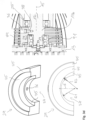
- Fig. 3c shows in sections perpendicular to the rotation axis 15 of the scroll vacuum pump Fig. 3a and 3b in the left illustration (section BB in Fig. 3b ) a view of the rear balancing weight 31 and in the right illustration (section AA in Fig. 3b ) the arrangement of a balancing section of the front balancing weight 39 in relation to the bellows 89, the flange bearing 91 and the eccentric section 19 of the drive shaft 17.
- FIG. 3c shows that the rear balancing weight, which is screwed to the drive shaft 17 by means of the central screw 83 and clamps the motor rotor 21 in the manner explained above, widens conically radially outwards. While maintaining the basic geometry of this rear balancing weight 31, it can be comparatively easily optimally adapted to different drive motors during its manufacture.
- the balancing section of the front balancing weight 29 shown in section is partially ring-shaped in such a way that the inner radius is adapted to the outer radius of the flange bearing 91.
- the available installation space is thus optimally utilized.
- the left illustration below shows the rear balancing weight 31 in a side view. Among other things, the holes 39a for the central screw 83 and the blind hole 39b for receiving the positioning pin 85 are shown.
- Fig. 3d shows in the two illustrations on the left the structure of the front balancing weight 39, which is formed in one piece and - as mentioned above - can be made of different materials, in particular from materials of different densities such as brass on the one hand and steel on the other.
- FIG. 3d shows an enlarged section of the Fig. 3b the arrangement of the front balancing weight 29 in the area of the eccentric section 19 of the drive shaft 17 and the flange bearing 91.
- the balancing weight 29 comprises three balancing sections 35 which, when installed, follow one another along the rotational axis 15 of the drive shaft 17.
- Each balancing section 35 has a partial ring shape, wherein, when installed, each balancing section points with its opening 37 towards the drive shaft 17 and encloses it.
- balancing sections 35 differ from each other in terms of the width of their openings 37. This is evident from the perspective view at the top left in Fig. 3d as well as the top view at the bottom left in Fig. 3d to be taken.
- each balancing section 35 is defined in a plane E perpendicular to the axis of rotation 15 (in the installed state) by a pitch circle with a constant radius along the central axis.
- a balancing section 35 with a radius R1 comprises, in the installed state, a section 17b of the drive shaft 17 which is located immediately behind the eccentric section 19.
- the adjacent balancing section 35 with the radius R2 comprises the flange bearing 91.
- the third balancing section 35 is located in an axial region on which heads of fastening screws for attaching the flange bearing 91 to the movable spiral component 13 are arranged.
- the radius of this balancing section 35 is therefore significantly larger than the radii R1, R2 of the other two balancing sections.
- a special feature is that the two radii R1, R2 are not the same size and the two pitch circles are not arranged concentrically, as is particularly evident the illustration below left in Fig. 3d can be taken.
- the center of the rear balancing section 35 in the installed state lies on the axis of rotation 15, since this balancing section includes the central section 17b of the drive shaft 17.
- the other center of the pitch circle with the larger radius R2 lies accordingly outside the openings 37 of the balancing sections 35.
- This design of the balancing weight 29 has the advantage that, without increasing the outer diameter, the center of mass of the middle balancing section 35 comprising the flange bearing 91 can be placed further radially outward than would be the case if the two centers coincided. In other words, a higher eccentric mass can be realized for this middle balancing section 35 without increasing the outer dimensions of the balancing weight 29.
- Fig. 3e shows three views of the rear balancing weight 31 on the left, which illustrate its construction.
- the balancing weight 31 is made in one piece.
- the balancing weight 31 comprises two balancing sections 39 which widen conically radially outwards.
- the balancing sections 39 each widen in a V-shape, defining an opening angle of approximately 20°.
- the balancing weight 31 comprises a circular cylinder section 40, the central axis of which, when installed, coincides with the axis of rotation 15 of the drive shaft 17.
- the thickness of this circular cylinder section 40 measured along the axis of rotation 15 is significantly smaller than the thickness of each balancing section 39.
- Fig. 3b can be removed, the balancing weight 31 with its circular cylinder section 40 faces the rear end of the drive shaft 17 when installed.
- the example of the scroll vacuum pump according to Fig. 2a and 2b It can be seen that the balancing weight 31 with its circular cylinder section 40 is inserted into the sleeve element 33.
- the balancing section 39 located between the circular cylinder section 40 and the outer balancing section 39 is shortened in the radial direction compared to the outer balancing section 39, but apart from that it is congruent with it and aligned so as to overlap. Both balancing sections 39 therefore widen in a V-shape, i.e. in a projection along the axis of rotation 15, the outlines of the two balancing sections 39 are delimited by two straight lines that diverge radially outwards in a V-shape. In addition, the two outlines of the balancing sections 39 are delimited by a radially inner circular section that has a smaller radius than a respective radially outer circular section that forms the radially outer boundary of the respective outline.
- the rear balancing weight 31 enables simple and cost-effective production as well as easy adaptation to the respective drive motor. However, adaptation is not absolutely necessary in every case.
- the rear balancing weight 31 can be designed in such a way that it can be used with the asynchronous motor of a scroll vacuum pump according to Fig. 2a and 2b , in particular with the sleeve element 33, as well as with the IPM motor of a scroll vacuum pump according to Fig. 3a and 3b can work together.
- a manufacturing arrangement 109 is shown in which a plurality of balancing weights 31 are arranged in a rosette-like manner on a circle. This illustrates that a plurality of balancing weights 31 can be manufactured by cutting from a flat material disk and then machining them individually.
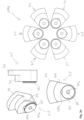
- Fig. 4 shows a view of the rear end of a scroll vacuum pump after Fig. 1a and 1b with the motor cover 103 removed. This shows the rear end face of the motor rotor 21, which is surrounded by a part of the motor stator 23.
- the motor rotor 21 is provided with cooling projections 47 protruding in the axial direction only on this rear end face.
- These cooling projections 47 are designed and arranged in such a way that they act as balancing weights.
- the balancing concept of the scroll vacuum pump according to Fig. 1a and 1b therefore includes not only the front balancing weight 91 and the rear balancing weight 31 arranged in front of the second bearing point 27, but also the balancing weights 47 arranged on the rear end face of the motor rotor 21, which also serve for cooling.
- These balancing weights or cooling projections 47 are plate-shaped and arranged in such a way that their wider side points in the circumferential direction. As a result, the cooling projections 47 can generate comparatively strong air movements during operation in the manner of blades in order to promote heat dissipation.
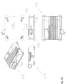
- the Fig. 5a shows the electronic housing 43 of the scroll vacuum pump Fig. 3a and 3b , whose drive motor is a single-phase IPM motor with an operating voltage of 24V/DC.
- the electronic equipment 45 includes a Sub-D connector, a standby switch, an on/off switch and USB ports.
- Fig. 5b shows the electronic housing 43 of the scroll vacuum pumps after Fig. 1a and 1b as well as Fig. 2a and 2b , each of which has a three-phase asynchronous motor as the drive motor.
- These asynchronous motors can be operated with an operating voltage of up to 480V/AC.
- the three-phase asynchronous motors require a higher protection class (particularly IP44) than the single-phase IPM motor, for which a lower protection class (particularly IP40) is sufficient.
- a housing cover 43b made of aluminum, for example, without its own seal is sufficient as a cover.
- a recessed arrangement is provided for the housing cover 43b in the housing part 43a, with surfaces set back inwards relative to the underside of a surrounding outer wall serving as a support for the housing cover 43b and each being provided with a sealing material. Due to its recessed arrangement, the housing cover 43b cannot be seen from the side.
- the housing cover 43b made of aluminum, for example, is placed on the underside of the housing part 43a.
- the underside is - like the recessed support surfaces in the housing part 43a according to Fig. 5a - provided with a sealing material, whereby additionally the inside of the housing cover 43b is completely covered with a sealing material consisting, for example, of cellular rubber.
- This provides a particularly effective seal for the electronics housing 43 in order to meet the requirements of the higher protection class.
- the electronic housings 43 also differ in terms of the respective electronic equipment 45.
- the electronic housing 43 according to Fig. 5a with a connection for a cold appliance plug 44, to which a power pack for supplying power to the scroll vacuum pump can be connected.
- the electronic housing 43 is Fig. 5b provided with a different mains plug 44, for example a mains plug of type Harting.
- the electronics housing 43 differs according to Fig. 5b from the electronics housing 43 according to Fig. 5a by the absence of the Sub-D connector, the standby switch, the on/off switch and the USB ports.
- the openings provided for this purpose in the housing component 43a are covered, for example with a film. This means that the electronic housing 43 can be designed in accordance with Fig. 5b an IP protection class can be made possible.
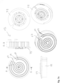
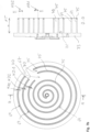
- Fig. 6a shows an overview of various views of a fixed spiral component 11, also referred to as a spiral housing, of a scroll vacuum pump according to the invention.
- the three upper views in Fig. 6a are enlarged in Fig. 6b shown, whereas the three lower representations of the Fig. 6a enlarged in Fig. 6c are shown.
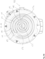
- FIG. 7a an overview with various representations of a movable spiral component 13, also referred to as orbiter, for the spiral casing 11 according to the Fig. 6a , 6b and 6c .
- the fixed spiral component 11 comprises a spiral arrangement with spiral walls 49 and spiral base 51 as well as a carrier 53 for the spiral arrangement.
- the two radially outer spiral walls 49 lie on concentric circles and are interrupted in the circumferential direction. This creates a parallel pumping structure of parallel pumping channels formed by the respective spiral grooves 50, which merge into a helical pumping channel formed by a helical spiral groove 50 and delimited by a helical spiral wall 49.
- the second part-circular spiral wall 49 viewed from the radial outside, has a greater thickness WD2 than the spiral-shaped spiral wall 49, which has a wall thickness WD1 in its radially further inner course.
- WD2 3.71 mm
- WD1 3.47 mm.
- the stability of the circular spiral wall 49 interrupted in the circumferential direction is increased by this increased thickness WD2.
- the spiral walls 49 are each provided with an elongated sealing element 75, also referred to as a tip seal, at their end facing away from the spiral base 51.
- the sealing element 75 for the spiral wall 49 located furthest radially outward has a comparatively large length, since it continues to the spiral wall 49 located further radially inward and extends to the radially inner end of this spiral wall 49 located in the area of the central axis of the spiral housing 11.
- a special feature of this long sealing element 75 is that it is located radially outward at the part-circular Spiral wall 49 is guided to the end 76 of this spiral wall 49, which extends to a gas inlet 67 (cf. Fig. 7a and 7b ) of the pumping system.
- the gas pumped along the spiral grooves 50 from radially outside to radially inside can exit the spiral grooves 50 via a central inlet opening 55 and via two bypass openings 61a, 63a into a channel system of the fixed spiral component 11, described in more detail below.
- These openings 55, 61a, 63a are each formed in the spiral base 51.
- the two bypass openings 61a, 63a are arranged offset from one another in the circumferential direction and are located on the same radius with respect to a central axis of the spiral housing 11.
- openings 56a, 61c, 63c Aligned with these openings 55, 61a, 63a are openings 56a, 61c, 63c formed on the side of the carrier 53 facing away from the spiral arrangement. These openings 56a, 61c, 63c serve to accommodate valves, which will be discussed in more detail elsewhere.
- an axial outlet opening 65 is formed radially further outward, which can optionally either be closed or form an axial gas outlet of the spiral housing 11 and thus of the pumping system of the scroll vacuum pump.
- the mentioned openings communicate with a channel system of the spiral casing 11, which is shown on the left and right in the illustrations.
- Fig. 6c shown.
- the central inlet opening 55 leads to an outlet channel 59 designed as a straight bore, which opens at the radial outlet 57 of the spiral casing 11.
- the one bypass opening 63a leads directly to this outlet channel 59.
- the channel section leading from there to the radial outlet 57 is thus not only a section of the outlet channel 59, but also forms a bypass channel 63 for gas originating from the bypass opening 63a.
- bypass channel 61 leads from the further bypass opening 61c to the outlet channel 59.
- This bypass channel 61 is part of a straight bore 64 which is introduced to produce the bypass channel 61.
- This bore 64 and the outlet channel 69 run at an angle to one another which corresponds to the angular offset of the two bypass openings 61c, 63c in the circumferential direction.
- the groove depth NT is comparatively large.
- the groove depth is 50 mm.
- a groove depth of 52 mm can be provided as an alternative. This then results in even larger ratios of groove depth to groove width.
- the movable spiral component 13 also comprises a spiral arrangement with spiral walls 69 and spiral base 71 as well as a plate-shaped support 73 for the spiral arrangement.
- the two radially outer spiral walls 69 run on concentric circles and are interrupted in the circumferential direction in the area of a gas inlet 67.
- a radially inner spiral wall 69 runs in a spiral shape.
- the spiral walls 69 are in turn provided with a sealing element 75 (tip seal) at their end facing away from the spiral base 71.
- these spiral walls 69 are provided with a thickness WD2, which is greater than the thickness WD1 of the spiral spiral wall 69.
- WD2 3.71 mm
- WD1 3.46 mm.
- the radially outer spiral groove 70 between the two part-circular spiral walls 69 has a groove width NB2, while the spiral-shaped spiral groove 70 delimited by the spiral spiral wall 69 has a groove width NB1.
- NB2 12.92 mm
- NB1 12.58 mm.
- NT 50 mm
- a groove depth of 52 mm can be provided as an alternative. This then results in even larger ratios of groove depth to groove width.
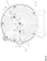
- Fig. 8a shows in an overview different views of the spiral casing of Fig. 6a , 6b and 6c and the orbiter of Fig. 7a and 7b comprehensive pumping system of the scroll vacuum pump according to Fig. 3a and 3b .
- the pumping system of the scroll vacuum pumps according to Fig. 1a and 1b as well as Fig. 2a and 2b is trained accordingly.
- Fig. 8b shows enlarged the top left image (section AA) of Fig. 8a .
- Fig. 8c shows an enlarged view of the top right (section BB) of Fig. 8a .
- Fig. 8d shows enlarged the illustration below right (section CC) of Fig. 8a .
- Fig. 8b The interaction of the interlocking spiral walls 49, 69 can be seen, which partially enclose crescent-shaped or sickle-shaped volumes.
- gas enters the chamber via the gas inlet 67, which is in Fig. 8b is only indicated with regard to its position (see, for example, Fig. 7b ), incoming gas to the center of the pump system and via the inlet opening 55 into the outlet channel 59 when the outlet valve 56 (see e.g. Fig. 8d ) opens at sufficiently high pressure.
- the pumped gas passes through the outlet channel 59 to the radial outlet 57 and thus to the outlet flange 78, if - as in Fig. 8d shown - the axial outlet opening 65 is closed by means of a plug 66.
- the radial outlet 57 can be closed and the plug 66 removed to create an axial outlet from the pumping system.
- Fig. 9 shows a concept referred to as a tapered gap design which can be provided in the inventive scroll vacuum pumps according to the present disclosure, namely in the region where the spirally extending spiral wall 49 of the fixed scroll member interacts with the spirally extending spiral wall 69 of the movable scroll member.
- the numerical values indicate the radial distance (in mm) between the facing wall surfaces, i.e. the size of the radial gap between the wall surfaces.
- the scroll vacuum pump is not in operation, i.e. the drive shaft does not rotate and the orbiter and thus its spiral wall 69 are stationary.
- the spiral casing and the orbiter are at ambient temperature.
- the special feature described here is that in this initial state the movable spiral wall 69 is arranged such that the gaps between the movable spiral wall 69 and the fixed spiral walls 49 each have a conical shape in the pumping direction P.
- the course of the movable spiral wall 69 is selected such that when the scroll vacuum pump is running, i.e. during operation, according to state II, the deformation of the movable spiral wall 69 reduces the conicity of the gap, as can be seen from the distance values. In state II, the movable spiral wall 69 therefore runs almost parallel to the two fixed spiral walls 49. The deformation of the movable spiral wall 69 results from the higher temperatures and the movement of the orbiter.
- Fig. 10 shows various external views of a scroll vacuum pump according to Fig. 3a and 3b .
- the pump housing 41 sits on the electronics housing 43 and is closed on the motor side by the motor cover 103 and on the opposite side by the hood 105.
- the outlet flange 78 and the inlet flange 77 are also shown.
- this pump housing 41 The special feature of this pump housing 41 is that the inlet flange 77, also referred to as the suction flange, is set back in this axial position relative to the highest point of the pump housing 41. This saves construction height. This is particularly advantageous when an alternative flange (not shown) is used, which is formed by an angle flange.
- Such a recessed arrangement of the inlet flange 77 is also possible in the scroll vacuum pump according to Fig. 2a and 2b intended.
Landscapes
- Engineering & Computer Science (AREA)
- Mechanical Engineering (AREA)
- General Engineering & Computer Science (AREA)
- Applications Or Details Of Rotary Compressors (AREA)
- Rotary Pumps (AREA)
Priority Applications (1)
| Application Number | Priority Date | Filing Date | Title |
|---|---|---|---|
| EP24197612.5A EP4506536B1 (fr) | 2023-08-08 | 2023-08-08 | Pompe à vide à spirales et système de pompe à vide à spirales |
Applications Claiming Priority (2)
| Application Number | Priority Date | Filing Date | Title |
|---|---|---|---|
| EP23190388.1A EP4253720B1 (fr) | 2023-08-08 | 2023-08-08 | Pompe à vide à spirales et système de pompe à vide à spirales |
| EP24197612.5A EP4506536B1 (fr) | 2023-08-08 | 2023-08-08 | Pompe à vide à spirales et système de pompe à vide à spirales |
Related Parent Applications (2)
| Application Number | Title | Priority Date | Filing Date |
|---|---|---|---|
| EP23190388.1A Division EP4253720B1 (fr) | 2023-08-08 | 2023-08-08 | Pompe à vide à spirales et système de pompe à vide à spirales |
| EP23190388.1A Division-Into EP4253720B1 (fr) | 2023-08-08 | 2023-08-08 | Pompe à vide à spirales et système de pompe à vide à spirales |
Publications (3)
| Publication Number | Publication Date |
|---|---|
| EP4506536A1 true EP4506536A1 (fr) | 2025-02-12 |
| EP4506536B1 EP4506536B1 (fr) | 2025-12-17 |
| EP4506536C0 EP4506536C0 (fr) | 2025-12-17 |
Family
ID=87567462
Family Applications (5)
| Application Number | Title | Priority Date | Filing Date |
|---|---|---|---|
| EP24197627.3A Active EP4506537B1 (fr) | 2023-08-08 | 2023-08-08 | Pompe à vide à spirales |
| EP25156934.9A Active EP4530471B1 (fr) | 2023-08-08 | 2023-08-08 | Pompe à vide à spirales et système de pompe à vide à spirales |
| EP23190388.1A Active EP4253720B1 (fr) | 2023-08-08 | 2023-08-08 | Pompe à vide à spirales et système de pompe à vide à spirales |
| EP24197612.5A Active EP4506536B1 (fr) | 2023-08-08 | 2023-08-08 | Pompe à vide à spirales et système de pompe à vide à spirales |
| EP25156928.1A Pending EP4530470A3 (fr) | 2023-08-08 | 2023-08-08 | Pompe à vide à spirales et système de pompe à vide à spirales |
Family Applications Before (3)
| Application Number | Title | Priority Date | Filing Date |
|---|---|---|---|
| EP24197627.3A Active EP4506537B1 (fr) | 2023-08-08 | 2023-08-08 | Pompe à vide à spirales |
| EP25156934.9A Active EP4530471B1 (fr) | 2023-08-08 | 2023-08-08 | Pompe à vide à spirales et système de pompe à vide à spirales |
| EP23190388.1A Active EP4253720B1 (fr) | 2023-08-08 | 2023-08-08 | Pompe à vide à spirales et système de pompe à vide à spirales |
Family Applications After (1)
| Application Number | Title | Priority Date | Filing Date |
|---|---|---|---|
| EP25156928.1A Pending EP4530470A3 (fr) | 2023-08-08 | 2023-08-08 | Pompe à vide à spirales et système de pompe à vide à spirales |
Country Status (3)
| Country | Link |
|---|---|
| EP (5) | EP4506537B1 (fr) |
| CN (1) | CN120693445A (fr) |
| WO (1) | WO2025032188A1 (fr) |
Cited By (1)
| Publication number | Priority date | Publication date | Assignee | Title |
|---|---|---|---|---|
| EP4538532A3 (fr) * | 2025-02-25 | 2025-08-27 | Pfeiffer Vacuum Technology AG | Pompe à vide à spirales |
Families Citing this family (4)
| Publication number | Priority date | Publication date | Assignee | Title |
|---|---|---|---|---|
| EP4407183A1 (fr) | 2024-05-31 | 2024-07-31 | Pfeiffer Vacuum Technology AG | Pompe à vide à spirales et son procédé de mise en oeuvre |
| EP4467810A3 (fr) | 2024-07-15 | 2025-02-26 | Pfeiffer Vacuum Technology AG | Pompe à vide à spirales et procédé de fabrication d'une pompe à vide à spirales |
| EP4621238A3 (fr) * | 2025-07-16 | 2025-11-12 | Pfeiffer Vacuum Technology AG | Procédé de montage d'une pompe à vide à spirales |
| EP4636251A3 (fr) | 2025-09-09 | 2026-04-29 | Pfeiffer Vacuum Technology AG | Pompe à vide à spirales |
Citations (5)
| Publication number | Priority date | Publication date | Assignee | Title |
|---|---|---|---|---|
| US20150004039A1 (en) * | 2013-06-28 | 2015-01-01 | Emerson Climate Technologies, Inc. | Capacity-modulated scroll compressor |
| EP3153708A1 (fr) | 2015-10-06 | 2017-04-12 | Pfeiffer Vacuum Gmbh | Pompe a spirales et procede destine au fonctionnement d'une pompe a spirales |
| EP3617511A2 (fr) | 2019-10-07 | 2020-03-04 | Pfeiffer Vacuum Gmbh | Pompes à spirales et procédé de fabrication pour des telles pompes |
| EP3647599A2 (fr) | 2019-10-07 | 2020-05-06 | Pfeiffer Vacuum Gmbh | Pompe à vide, pompe d'extraction et procédé de fabrication des telles pompes |
| CN113431781A (zh) * | 2021-08-05 | 2021-09-24 | 临海市谭氏真空设备有限公司 | 干式涡旋真空泵 |
Family Cites Families (22)
| Publication number | Priority date | Publication date | Assignee | Title |
|---|---|---|---|---|
| GB809445A (en) * | 1954-02-27 | 1959-02-25 | Heraeus Gmbh W C | Improvements in or relating to rotary high vacuum pumps |
| JPS60206989A (ja) * | 1984-03-30 | 1985-10-18 | Mitsubishi Electric Corp | スクロ−ル形流体機械 |
| US6884047B1 (en) * | 2003-10-20 | 2005-04-26 | Varian, Inc. | Compact scroll pump |
| DE102006058842A1 (de) * | 2006-12-13 | 2008-06-19 | Pfeiffer Vacuum Gmbh | Vakuumpumpe mit Lüfter |
| FR2968731B1 (fr) * | 2010-12-13 | 2015-02-27 | Danfoss Commercial Compressors | Systeme thermodynamique equipe d'une pluralite de compresseurs |
| CN102817840B (zh) * | 2011-06-07 | 2014-08-27 | 思科涡旋科技(杭州)有限公司 | 一种带有绕动式推力轴承的涡卷式容积位移装置 |
| US9605676B2 (en) * | 2013-05-31 | 2017-03-28 | Emerson Climate Technologies, Inc. | Variable speed scroll compressor |
| JP6165576B2 (ja) * | 2013-09-30 | 2017-07-19 | 株式会社日立産機システム | スクロール式流体機械 |
| CN105443377A (zh) * | 2014-06-10 | 2016-03-30 | 丹佛斯(天津)有限公司 | 涡旋压缩机 |
| US10954944B2 (en) * | 2015-04-27 | 2021-03-23 | Emerson Climate Technologies, Inc. | Compressor having counterweight assembly |
| JP6325041B2 (ja) * | 2016-08-31 | 2018-05-16 | 三菱重工サーマルシステムズ株式会社 | スクロール流体機械およびチップシール |
| DE102019108079B4 (de) * | 2018-03-30 | 2023-08-31 | Kabushiki Kaisha Toyota Jidoshokki | Schneckenverdichter |
| EP3597922B1 (fr) * | 2018-07-19 | 2024-08-28 | Agilent Technologies, Inc. (A Delaware Corporation) | Système de pompage à vide comportant une pompe à vide lubrifiée à l'huile |
| EP3963209B1 (fr) * | 2019-04-30 | 2025-07-30 | Agilent Technologies, Inc. | Palier de butée à film d'huile double face dans une pompe à spirale |
| CN110159528B (zh) * | 2019-05-23 | 2020-11-17 | 浙江大学 | 一种双侧双槽并联式无油涡旋空压机 |
| CN110185614B (zh) * | 2019-06-26 | 2020-10-02 | 浙江大学 | 一种干式双涡旋真空泵 |
| JP2021014801A (ja) * | 2019-07-10 | 2021-02-12 | ダイキン工業株式会社 | スクロール圧縮機 |
| JP7220692B2 (ja) * | 2019-10-07 | 2023-02-10 | プファイファー・ヴァキューム・ゲーエムベーハー | 真空ポンプ、スクロールポンプ及びその製造方法 |
| EP3708840B1 (fr) * | 2020-07-22 | 2025-02-26 | Pfeiffer Vacuum Technology AG | Pompe à vide avec clapet antiretour |
| JP7534951B2 (ja) * | 2020-12-22 | 2024-08-15 | サンデン株式会社 | スクロール型圧縮機 |
| EP3940234B1 (fr) * | 2021-09-29 | 2023-08-23 | Pfeiffer Vacuum Technology AG | Pompe et procédé de fabrication d'une couche antifriction |
| CN116470689A (zh) * | 2023-03-27 | 2023-07-21 | 北京通嘉宏瑞科技有限公司 | 一体轴式真空泵电机 |
-
2023
- 2023-08-08 EP EP24197627.3A patent/EP4506537B1/fr active Active
- 2023-08-08 EP EP25156934.9A patent/EP4530471B1/fr active Active
- 2023-08-08 EP EP23190388.1A patent/EP4253720B1/fr active Active
- 2023-08-08 EP EP24197612.5A patent/EP4506536B1/fr active Active
- 2023-08-08 EP EP25156928.1A patent/EP4530470A3/fr active Pending
-
2024
- 2024-08-08 WO PCT/EP2024/072497 patent/WO2025032188A1/fr active Pending
- 2024-08-08 CN CN202480015459.0A patent/CN120693445A/zh active Pending
Patent Citations (5)
| Publication number | Priority date | Publication date | Assignee | Title |
|---|---|---|---|---|
| US20150004039A1 (en) * | 2013-06-28 | 2015-01-01 | Emerson Climate Technologies, Inc. | Capacity-modulated scroll compressor |
| EP3153708A1 (fr) | 2015-10-06 | 2017-04-12 | Pfeiffer Vacuum Gmbh | Pompe a spirales et procede destine au fonctionnement d'une pompe a spirales |
| EP3617511A2 (fr) | 2019-10-07 | 2020-03-04 | Pfeiffer Vacuum Gmbh | Pompes à spirales et procédé de fabrication pour des telles pompes |
| EP3647599A2 (fr) | 2019-10-07 | 2020-05-06 | Pfeiffer Vacuum Gmbh | Pompe à vide, pompe d'extraction et procédé de fabrication des telles pompes |
| CN113431781A (zh) * | 2021-08-05 | 2021-09-24 | 临海市谭氏真空设备有限公司 | 干式涡旋真空泵 |
Cited By (1)
| Publication number | Priority date | Publication date | Assignee | Title |
|---|---|---|---|---|
| EP4538532A3 (fr) * | 2025-02-25 | 2025-08-27 | Pfeiffer Vacuum Technology AG | Pompe à vide à spirales |
Also Published As
| Publication number | Publication date |
|---|---|
| EP4530470A3 (fr) | 2025-07-02 |
| EP4253720A3 (fr) | 2024-06-19 |
| WO2025032188A1 (fr) | 2025-02-13 |
| EP4530471A2 (fr) | 2025-04-02 |
| EP4253720C0 (fr) | 2025-10-01 |
| EP4506536B1 (fr) | 2025-12-17 |
| EP4530471C0 (fr) | 2026-02-25 |
| EP4506537C0 (fr) | 2025-10-08 |
| CN120693445A (zh) | 2025-09-23 |
| EP4530471A3 (fr) | 2025-07-02 |
| EP4506536C0 (fr) | 2025-12-17 |
| EP4253720A2 (fr) | 2023-10-04 |
| EP4506537B1 (fr) | 2025-10-08 |
| EP4530471B1 (fr) | 2026-02-25 |
| EP4253720B1 (fr) | 2025-10-01 |
| EP4506537A1 (fr) | 2025-02-12 |
| EP4530470A2 (fr) | 2025-04-02 |
Similar Documents
| Publication | Publication Date | Title |
|---|---|---|
| EP4506537B1 (fr) | Pompe à vide à spirales | |
| DE69618612T2 (de) | Einrichtung zur erzeugung einer nachgiebigen radialen andruckkraft mit hilfe eines gleitenden blocks für spiral verdrängermaschine | |
| DE102011001041B9 (de) | Magnetisch angetriebene Pumpenanordnung mit einer Mikropumpe mit Zwangsspuelung und Arbeitsverfahren | |
| EP2273124B1 (fr) | Pompe centrifuge et procédé d'équilibrage de la poussée axiale dans une pompe centrifuge | |
| DE19518101A1 (de) | Selbstansaugende Pumpe | |
| DE3800324A1 (de) | Fluegelzellenverdichter | |
| DE10223958A1 (de) | Schneckenkompressor | |
| DE102009056231A1 (de) | Schneckenverdichter (Scroll-Verdichter) | |
| DE112016004496T5 (de) | Pumpvorrichtungen | |
| DE3521284C2 (fr) | ||
| DE69928172T2 (de) | Vacuumpumpe | |
| EP1309799A1 (fr) | Compresseur a vis | |
| DE69726477T2 (de) | Seitenkanalpumpe mit speziell geformten Schaufeln und Seitenkanälen | |
| EP1343645A2 (fr) | Appareil de chauffage automobile comportant une pompe de recirculation de caloporteur integree | |
| EP0116136A2 (fr) | Compresseur rotatif | |
| DE4220830A1 (de) | Fluidverdichter | |
| DE4220713C2 (de) | Rotationskolbenverdichter | |
| DE102020103384B4 (de) | Schraubenverdichter mit einseitig gelagerten Rotoren | |
| DE4121510C2 (de) | Rotationskolbenverdichter mit einem geschlossenen Gehäuse | |
| DE4234055C2 (de) | Spiralkompressor | |
| DE19622722A1 (de) | Mikromotor und Mikropumpe | |
| EP4180665B1 (fr) | Pompe á engrenages internes avec poches de pression sur la roue creuse et/ou sur le boîtier | |
| WO2010054864A1 (fr) | Machine rotative | |
| DE4143555C2 (de) | Rotationskolbenverdichter | |
| DE19742881B4 (de) | Radialer Schwenkmotor |
Legal Events
| Date | Code | Title | Description |
|---|---|---|---|
| PUAI | Public reference made under article 153(3) epc to a published international application that has entered the european phase |
Free format text: ORIGINAL CODE: 0009012 |
|
| STAA | Information on the status of an ep patent application or granted ep patent |
Free format text: STATUS: THE APPLICATION HAS BEEN PUBLISHED |
|
| AC | Divisional application: reference to earlier application |
Ref document number: 4253720 Country of ref document: EP Kind code of ref document: P |
|
| AK | Designated contracting states |
Kind code of ref document: A1 Designated state(s): AL AT BE BG CH CY CZ DE DK EE ES FI FR GB GR HR HU IE IS IT LI LT LU LV MC ME MK MT NL NO PL PT RO RS SE SI SK SM TR |
|
| STAA | Information on the status of an ep patent application or granted ep patent |
Free format text: STATUS: REQUEST FOR EXAMINATION WAS MADE |
|
| 17P | Request for examination filed |
Effective date: 20250430 |
|
| STAA | Information on the status of an ep patent application or granted ep patent |
Free format text: STATUS: EXAMINATION IS IN PROGRESS |
|
| 17Q | First examination report despatched |
Effective date: 20250715 |
|
| GRAP | Despatch of communication of intention to grant a patent |
Free format text: ORIGINAL CODE: EPIDOSNIGR1 |
|
| STAA | Information on the status of an ep patent application or granted ep patent |
Free format text: STATUS: GRANT OF PATENT IS INTENDED |
|
| INTG | Intention to grant announced |
Effective date: 20250930 |
|
| GRAS | Grant fee paid |
Free format text: ORIGINAL CODE: EPIDOSNIGR3 |
|
| GRAA | (expected) grant |
Free format text: ORIGINAL CODE: 0009210 |
|
| STAA | Information on the status of an ep patent application or granted ep patent |
Free format text: STATUS: THE PATENT HAS BEEN GRANTED |
|
| AC | Divisional application: reference to earlier application |
Ref document number: 4253720 Country of ref document: EP Kind code of ref document: P |
|
| AK | Designated contracting states |
Kind code of ref document: B1 Designated state(s): AL AT BE BG CH CY CZ DE DK EE ES FI FR GB GR HR HU IE IS IT LI LT LU LV MC ME MK MT NL NO PL PT RO RS SE SI SK SM TR |
|
| REG | Reference to a national code |
Ref country code: CH Ref legal event code: F10 Free format text: ST27 STATUS EVENT CODE: U-0-0-F10-F00 (AS PROVIDED BY THE NATIONAL OFFICE) Effective date: 20251217 Ref country code: GB Ref legal event code: FG4D Free format text: NOT ENGLISH |
|
| REG | Reference to a national code |
Ref country code: DE Ref legal event code: R096 Ref document number: 502023002534 Country of ref document: DE |
|
| U01 | Request for unitary effect filed |
Effective date: 20260108 |
|
| U07 | Unitary effect registered |
Designated state(s): AT BE BG DE DK EE FI FR IT LT LU LV MT NL PT RO SE SI Effective date: 20260113 |
|
| PG25 | Lapsed in a contracting state [announced via postgrant information from national office to epo] |
Ref country code: NO Free format text: LAPSE BECAUSE OF FAILURE TO SUBMIT A TRANSLATION OF THE DESCRIPTION OR TO PAY THE FEE WITHIN THE PRESCRIBED TIME-LIMIT Effective date: 20260317 |
|
| PG25 | Lapsed in a contracting state [announced via postgrant information from national office to epo] |
Ref country code: HR Free format text: LAPSE BECAUSE OF FAILURE TO SUBMIT A TRANSLATION OF THE DESCRIPTION OR TO PAY THE FEE WITHIN THE PRESCRIBED TIME-LIMIT Effective date: 20251217 |
|
| PG25 | Lapsed in a contracting state [announced via postgrant information from national office to epo] |
Ref country code: RS Free format text: LAPSE BECAUSE OF FAILURE TO SUBMIT A TRANSLATION OF THE DESCRIPTION OR TO PAY THE FEE WITHIN THE PRESCRIBED TIME-LIMIT Effective date: 20260317 |