EP4564491A1 - Verfahren zum zusammenbau einer batteriezelle - Google Patents
Verfahren zum zusammenbau einer batteriezelle Download PDFInfo
- Publication number
- EP4564491A1 EP4564491A1 EP23307093.7A EP23307093A EP4564491A1 EP 4564491 A1 EP4564491 A1 EP 4564491A1 EP 23307093 A EP23307093 A EP 23307093A EP 4564491 A1 EP4564491 A1 EP 4564491A1
- Authority
- EP
- European Patent Office
- Prior art keywords
- vacuum chamber
- cup
- assembly method
- cover
- interior space
- Prior art date
- Legal status (The legal status is an assumption and is not a legal conclusion. Google has not performed a legal analysis and makes no representation as to the accuracy of the status listed.)
- Pending
Links
Images


Classifications
-
- H—ELECTRICITY
- H01—ELECTRIC ELEMENTS
- H01M—PROCESSES OR MEANS, e.g. BATTERIES, FOR THE DIRECT CONVERSION OF CHEMICAL ENERGY INTO ELECTRICAL ENERGY
- H01M50/00—Constructional details or processes of manufacture of the non-active parts of electrochemical cells other than fuel cells, e.g. hybrid cells
- H01M50/10—Primary casings; Jackets or wrappings
- H01M50/147—Lids or covers
- H01M50/166—Lids or covers characterised by the methods of assembling casings with lids
- H01M50/169—Lids or covers characterised by the methods of assembling casings with lids by welding, brazing or soldering
-
- H—ELECTRICITY
- H01—ELECTRIC ELEMENTS
- H01M—PROCESSES OR MEANS, e.g. BATTERIES, FOR THE DIRECT CONVERSION OF CHEMICAL ENERGY INTO ELECTRICAL ENERGY
- H01M10/00—Secondary cells; Manufacture thereof
- H01M10/04—Construction or manufacture in general
- H01M10/049—Processes for forming or storing electrodes in the battery container
-
- H—ELECTRICITY
- H01—ELECTRIC ELEMENTS
- H01M—PROCESSES OR MEANS, e.g. BATTERIES, FOR THE DIRECT CONVERSION OF CHEMICAL ENERGY INTO ELECTRICAL ENERGY
- H01M50/00—Constructional details or processes of manufacture of the non-active parts of electrochemical cells other than fuel cells, e.g. hybrid cells
- H01M50/10—Primary casings; Jackets or wrappings
- H01M50/102—Primary casings; Jackets or wrappings characterised by their shape or physical structure
- H01M50/103—Primary casings; Jackets or wrappings characterised by their shape or physical structure prismatic or rectangular
-
- H—ELECTRICITY
- H01—ELECTRIC ELEMENTS
- H01M—PROCESSES OR MEANS, e.g. BATTERIES, FOR THE DIRECT CONVERSION OF CHEMICAL ENERGY INTO ELECTRICAL ENERGY
- H01M50/00—Constructional details or processes of manufacture of the non-active parts of electrochemical cells other than fuel cells, e.g. hybrid cells
- H01M50/10—Primary casings; Jackets or wrappings
- H01M50/116—Primary casings; Jackets or wrappings characterised by the material
- H01M50/117—Inorganic material
- H01M50/119—Metals
-
- H—ELECTRICITY
- H01—ELECTRIC ELEMENTS
- H01M—PROCESSES OR MEANS, e.g. BATTERIES, FOR THE DIRECT CONVERSION OF CHEMICAL ENERGY INTO ELECTRICAL ENERGY
- H01M50/00—Constructional details or processes of manufacture of the non-active parts of electrochemical cells other than fuel cells, e.g. hybrid cells
- H01M50/10—Primary casings; Jackets or wrappings
- H01M50/147—Lids or covers
- H01M50/155—Lids or covers characterised by the material
- H01M50/157—Inorganic material
- H01M50/159—Metals
-
- H—ELECTRICITY
- H01—ELECTRIC ELEMENTS
- H01M—PROCESSES OR MEANS, e.g. BATTERIES, FOR THE DIRECT CONVERSION OF CHEMICAL ENERGY INTO ELECTRICAL ENERGY
- H01M10/00—Secondary cells; Manufacture thereof
- H01M10/05—Accumulators with non-aqueous electrolyte
- H01M10/056—Accumulators with non-aqueous electrolyte characterised by the materials used as electrolytes, e.g. mixed inorganic/organic electrolytes
- H01M10/0561—Accumulators with non-aqueous electrolyte characterised by the materials used as electrolytes, e.g. mixed inorganic/organic electrolytes the electrolyte being constituted of inorganic materials only
- H01M10/0562—Solid materials
-
- H—ELECTRICITY
- H01—ELECTRIC ELEMENTS
- H01M—PROCESSES OR MEANS, e.g. BATTERIES, FOR THE DIRECT CONVERSION OF CHEMICAL ENERGY INTO ELECTRICAL ENERGY
- H01M10/00—Secondary cells; Manufacture thereof
- H01M10/05—Accumulators with non-aqueous electrolyte
- H01M10/056—Accumulators with non-aqueous electrolyte characterised by the materials used as electrolytes, e.g. mixed inorganic/organic electrolytes
- H01M10/0564—Accumulators with non-aqueous electrolyte characterised by the materials used as electrolytes, e.g. mixed inorganic/organic electrolytes the electrolyte being constituted of organic materials only
- H01M10/0565—Polymeric materials, e.g. gel-type or solid-type
-
- H—ELECTRICITY
- H01—ELECTRIC ELEMENTS
- H01M—PROCESSES OR MEANS, e.g. BATTERIES, FOR THE DIRECT CONVERSION OF CHEMICAL ENERGY INTO ELECTRICAL ENERGY
- H01M2220/00—Batteries for particular applications
- H01M2220/20—Batteries in motive systems, e.g. vehicle, ship, plane
-
- H—ELECTRICITY
- H01—ELECTRIC ELEMENTS
- H01M—PROCESSES OR MEANS, e.g. BATTERIES, FOR THE DIRECT CONVERSION OF CHEMICAL ENERGY INTO ELECTRICAL ENERGY
- H01M2300/00—Electrolytes
- H01M2300/0017—Non-aqueous electrolytes
- H01M2300/0065—Solid electrolytes
Definitions
- the invention relates, in general, to the technical field of solid-state batteries and electric batteries intended for electric or hybrid vehicles.
- the invention relates more specifically to a method of assembling solid-state battery cells used in electric vehicles.
- Motor vehicles with electric or hybrid traction or propulsion have one or more battery modules connected to a power network to supply an electric motor (traction or propulsion).
- Each battery module comprises at least one electrochemical cell generating current by chemical reaction, for example a lithium-ion cell.
- a battery cell is in the form of a metal casing consisting of a rigid cup having an opening and a plate forming the cup cover, the cover and cup assembled together defining an interior space of the cell.
- the cup is filled with at least one stack of positive electrodes forming a cathode, negative electrodes forming an anode, and a separator disposed between each pair of electrodes. Once the stack is inserted into the cup, the cell lid is sealed to the cup.
- a liquid electrolyte is injected into an insertion hole formed in the cell cover, so that the stack bathes in the electrolyte, this which promotes the movement of electrons from one electrode to the other.
- the insertion hole in the cell cover is closed and the cell is vacuum sealed to prevent the introduction of impurities into the interior space of the cell.
- liquid electrolyte in the cell is flammable and can damage the rest of the battery, particularly around the affected cell.
- the solid electrolyte is not flammable, but unlike the liquid electrolyte, it does not occupy the entire volume of the cell, which facilitates the introduction of oxygen from the ambient air into the empty areas of the cell's interior space. This presence of oxygen accelerates the oxidation of the contained electrodes and can ultimately reduce the battery's lifespan. Furthermore, aging and/or prolonged use of the battery can cause unwanted chemical reactions within the cell. These chemical reactions increase the internal pressure of the cell and create a swelling effect, commonly known in English as the "swelling effect.”
- the invention aims to remedy all or part of the drawbacks of the state of the art by proposing in particular a method for assembling a battery cell with an entirely solid electrolyte, the method making it possible to reduce the swelling effect of the cell and to increase the lifespan of the battery in which it is integrated.
- the battery cell has a rigid housing, and is preferably a so-called "prismatic" cell, i.e. the cell cup is a rectangular parallelepiped having an opening.
- the cup is made of metallic material(s), for example formed from aluminum alloys or stainless steels.
- the battery cell housing preferably consists of the cup and the cover.
- the invention thus provides a method for assembling battery cell housings that makes it possible to limit the effects of swelling of the housings and that does not require more steps than an assembly method known in the state of the art. Indeed, by closing the housing when sealing the cover on the cup while the latter is placed in the vacuum chamber with a predetermined internal pressure strictly lower than atmospheric pressure, a closed cell will be obtained whose interior space in which the electrodes and electrolyte are placed, has an internal pressure that is also strictly lower than atmospheric pressure, making it possible to compensate for swelling effects for a longer period.
- step (I) of positioning the cover and the cup in the vacuum chamber is preceded by a step (i) of filling the cup with a dry battery component.
- the dry battery component notably comprises a stack of positive electrodes and negative electrodes separated by a solid electrolyte.
- step (I) of positioning the cover and the bucket in the vacuum chamber is preceded by at least one step (ii) of positioning the bucket of the cell on a work table of a tool.
- the tool comprises a work table.
- the bucket is positioned on the work table to be placed in the vacuum chamber.
- the work table contains holding means allowing the placement of the bucket on a specific surface of the work table.
- the holding means contain a compression system exerting a prestress on the bucket, the prestress making it possible to limit the effects of swelling of the cell after its sealing.
- the vacuum chamber comprises a rigid enclosure delimiting with the work table the interior space of the vacuum chamber.
- the vacuum chamber is preferably parallelepipedal in shape and may have an opening, the opening being closed by the work table during step (I) of positioning the cover and the bucket in the vacuum chamber.
- the interior space of the vacuum chamber forms a closed space when step (I) of positioning the cover and the bucket in the vacuum chamber is carried out.
- the tooling comprises a conveyor device, the work table moving along a conveyor path driven by the conveyor device.
- a conveyor device bringing the work table(s) makes it possible to define a rate of conveyance of the buckets into the vacuum chamber, such a conveyor device being particularly suitable for chain or series assemblies of battery cell housings.
- the predetermined pressure in the interior space of the vacuum chamber is applied by pressure control means comprising for example at least one vacuum pump, preferably a positive displacement pump.
- the vacuum pump is connected to the interior space of the vacuum chamber, for example via a vacuum pump hose inserted into an opening of the vacuum chamber.
- the vacuum pump is automated to apply the predetermined pressure for a predetermined duration and then to restore atmospheric pressure in the interior space of the vacuum chamber, and this, at regular intervals.
- the predetermined pressure applied in the interior space of the vacuum chamber is less than or equal to 1 Pa, preferably less than or equal to 10 -2 Pa, more preferably less than or equal to 10 -5 Pa.
- the vacuum pump gradually applies pressure in the interior space of the vacuum chamber until the predetermined pressure is reached. Applying a pressure lower than atmospheric pressure makes it possible to reduce the amount of oxygen present inside the cell housing and thus to limit the risks of oxidation of the electrodes of the housing once the housing is sealed.
- the sealing of the lid with the cup by the sealing means is a gas-tight seal.
- the tightness of the sealing of the lid with the cup is verified by a helium leak test.
- the sealing means are located outside the vacuum chamber.
- the sealing means comprise at least one laser, the step of sealing the lid with the cup comprising a laser welding step.
- a vacuum chamber to carry out the step of laser welding the lid with the cup makes it possible to obtain an efficient assembly method, requiring less energy and producing less spatter than laser welding carried out in ambient air.
- Laser welding makes it possible to best preserve the mechanical properties of the housing after its sealing.
- the laser comprises a solid-state or gas laser.
- the solid-state or gas laser is located opposite a translucent, preferably transparent, wall or window of the vacuum chamber and is preferably fixed to the vacuum chamber using a transmission interface so as to move simultaneously with the vacuum chamber.
- the laser moves in longitudinal and transverse directions relative to the wall or window of the vacuum chamber.
- the laser welds the outer contour of the lid of the housing, following a predefined path.
- the housing delimits a closed interior space having an internal pressure less than or equal to 1 Pa, preferably less than or equal to 10 -2 Pa, more preferably less than or equal to 10 -5 Pa.
- the assembly method allows the interior space of the housing to contain only a very small quantity of oxygen, thus guaranteeing a gas-tight seal.
- the enclosure of the vacuum chamber is at least partly movable between an open position and a closed position, the open position allowing step (I) of positioning the cover and the bucket in the interior space of the vacuum chamber to be carried out.
- the enclosure designates the walls of the vacuum chamber.
- the entire enclosure is movable at least vertically between the open position and the closed position.
- the enclosure comprises at least one opening movable between an open position and a closed position.
- the invention also relates to an assembly assembly comprising at least one vacuum chamber, means for controlling the internal pressure of the vacuum chamber and sealing means, the assembly assembly being characterized in that it is configured to implement the method of assembling a housing of a battery cell as described above.
- the invention also relates to a battery cell obtained directly by the assembly method as described above.
- the housing delimits a closed interior space having an internal pressure less than or equal to 1 Pa, preferably less than or equal to 10 -2 Pa, more preferably less than or equal to 10 -5 Pa.
- FIG. 1 illustrates the steps of a method 10 for assembling a housing 12 of a battery cell, the method 10 being able to be adapted to different embodiments represented in the figures 2 , 3 And 4 .
- the cell housing 12 of the assembly method 10 consists of a cup 14 and a cover 16.
- the cup 14 is parallelepipedal and made of metallic material(s), for example aluminum or stainless steel. It has an opening on an upper face of the parallelepiped, the opening being intended to be closed by the cover 16.
- the cover 16 of the cell housing 12 comprises a positive terminal and a negative terminal allowing the cell to be electrically connected in series or in parallel to other cells after assembly of the housing 12.
- An upstream step (i) of the assembly method 10 consists of filling the cup 14 with a battery component such as a dry battery component, the component being formed of positive electrodes, negative electrodes and a solid electrolyte integrated in the positive and negative electrodes.
- a battery component such as a dry battery component, the component being formed of positive electrodes, negative electrodes and a solid electrolyte integrated in the positive and negative electrodes.
- step (ii) of the method 10 subsequent to step (i), the cup 14, covered with the cover 16 of the housing 12, is positioned on a tool 18. At this step of the method 10, no stress is applied between the cover 16 and the cup 14.
- filling (i) can also be carried out after positioning (ii) of the cup 14 on the tool 18; however, in this case, the filling step would be likely to slow down the production line during series assembly.
- the tool 18 comprises a work table 19 intended to support, and preferably also to immobilize the bucket 14 of the housing 12 of the cell.
- the work table 19 comprises a rectangular plate made of plastic and/or metal material(s), preferably of only metal material(s).
- the plate comprises holding means, for example a rectangular frame, clamps or any other instrument for holding the cup 14 of the housing 12 in place.
- the holding means (not illustrated) are directly formed on the plate of the work table 19.
- the holding means may be attached to the plate using fixing elements, for example screws.
- the holding means may further comprise a system for compressing the cup 14 intended to exert a prestress on lateral faces of the cup 14.
- the tool 18 supporting the bucket 14 covered with the cover 16 is placed on a lower wall 201 of a vacuum chamber 20 forming the work table.
- the work table 19 can be permanently fixed on the lower wall 201 of the vacuum chamber 20. According to another embodiment, the work table 19, once installed in the vacuum chamber 20, forms the lower wall 201 of the vacuum chamber 20.
- a locking system (not shown in the figures) makes it possible to maintain the closure of the movable door 23 of the enclosure 22 in a locked state to ensure gas-tightness in the interior space 24 of the vacuum chamber 20.
- a safety system can be added in association with this closing system, for example an emergency button or “punch” button.
- a step (II) of the assembly method 10 consists in applying, subsequently to step (I), a predetermined pressure in the interior space 24 of the vacuum chamber 20.
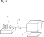
- the vacuum chamber 20 is connected to a pipe 170 of a vacuum pump 17 (shown in the Figure 5 ) placed at a distance from the vacuum chamber 20.
- the vacuum pump 17 may be a positive displacement pump, or a pump volumetric.
- the vacuum pump 17 is capable of applying pressure in the interior space 24 of the vacuum chamber 20 until the predetermined pressure is reached.
- the predetermined pressure is less than or equal to 1 Pa, preferably less than or equal to 10 -2 Pa, more preferably less than or equal to 10 -5 Pa.
- the cover 16 is sealed to the cup 14 of the cell housing 12 using sealing means 26.
- the sealing means 26 comprise a laser 28 fixed at a distance from the transparent upper wall 202 of the vacuum chamber, and a laser transmission interface 29, the laser 28 comprising a solid-state or gas laser.
- the laser 28 is able to move in transverse and vertical directions relative to the transparent upper wall 202 of the vacuum chamber 20, so as to weld the cover 16 and the cup 14 to obtain a closed gas-tight housing 12 .
- the housing 12 delimits a closed interior space 30 in which the internal pressure is less than or equal to 1 Pa, preferably less than or equal to 10 -2 Pa, more preferably less than or equal to 10 -5 Pa.
- the transparent wall can equip a wall other than the upper wall.
- the enclosure 22 is provided with a translucent window, preferably transparent, configured to allow the action of the sealing means such as the laser for sealing the cover 16 to the cup 14.
- Means for redirecting the laser beam(s) may also be provided in the interior space 24 of the vacuum chamber. These redirection means may be reflective mirrors and may be controlled by movement means to control their position, for example their orientation. This makes it possible in particular to be able to move the laser beam without depending on the size of the window of the enclosure 22.
- a step (IV) of the method 10 consists of restoring atmospheric pressure in the interior space 24 of the vacuum chamber 20.
- the vacuum pump 17 is deactivated and/or the enclosure 22 moves from a closed position to an open position.
- a pressure control unit may control the pressure in the interior space 24 of the vacuum chamber 20 to enable the steps of sealing the lid 16 with the cup 14 and restoring atmospheric pressure in the interior space 24 of the vacuum chamber 20.
- the assembly method 10 shown according to the embodiment of the Figure 2 is advantageously provided for manual or robotic loading of the vacuum chamber 20, in which method 10 an operator or a robot arm must place and remove each housing 12 from the vacuum chamber 20.
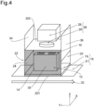
- THE figures 3 And 4 represent the assembly process 10 of the Figure 1 according to a second and a third embodiment, particularly advantageous for the chain or series production of 12 cell boxes.
- the embodiments of the assembly method 10 of the figures 3 And 4 differ from that shown on the Figure 1 essentially in that, during step (ii) of positioning the bucket 14 on the tooling 18, the bucket 14 is positioned on the work table 19 which is itself conveyed into the vacuum chamber 20 using a conveyor device 21, the work table 19 moving on the conveyor device 21 along a conveyor path 32 transverse to the vacuum chamber 20.
- the conveyor device 21 is immobilized when the work table 19 is positioned so as to form, with the enclosure 22 in the closed position, the interior space 24 of the vacuum chamber 20.
- the conveyor device 21 is controlled to stop at regular time intervals over a determined duration and/or contains position sensors making it possible to locate the position of the work table 19 relative to the enclosure 22.
- the enclosure 22 of the vacuum chamber 20 is entirely movable, at least vertically, between the open position, allowing the work table 19 supporting the bucket 14 to be conveyed by the conveyor device 21, and the closed position, in which the enclosure 22 and the work table form the interior space 24 of the vacuum chamber 20.
- the enclosure 22 can also be movable in rotation about a hinge axis allowing the enclosure 22 to move from the open position to the closed position as described above.
- Step (I) of positioning the cover 16 and the bucket 14 in the vacuum chamber 20 shown in the embodiment of the Figure 4 differs from that of the Figure 3 in that the enclosure 22 contains two opposite openings ( 34, 36 ) movable between the open position and the closed position.
- the opposite openings ( 34, 36 ) are two walls of the enclosure 22, the two walls being vertically movable.
- the opposite openings ( 34, 36 ) are rotatable about hinge axes.
- the two openings ( 34, 36 ) of the enclosure 22 allow the bucket 14 and the work table 19 to be conveyed into the vacuum chamber 20.
- the closed position the two openings ( 34, 36 ) of the enclosure 22 close the vacuum chamber 20 in a sealed manner.
- the two movable openings ( 34, 36 ) translate simultaneously and are controlled by a control device.
- the movements and displacements of the enclosure 22 and the conveyor device 21 are controlled and synchronized by control means so as to optimize production.
- the enclosure 22 is kept in the open position, while the conveyor device 21 is in movement until the work table 19 reaches the level of the enclosure 22.
- the enclosure 22 passes into a closed position for a time interval corresponding to the time taken to carry out steps (II), (III) and optionally (IV) of the method 10.
- the enclosure 22 is restored to an open position and the device conveys another work table 19 there.
- Such an assembly method can be integrated into a battery production line, the production line comprising for example a station for producing the cup and the cover, a station for filling the cup, a station for assembling the battery cell housings according to the assembly method 10 implemented in the embodiments of the figures 3 And 4 and a station for assembling battery modules from the housings obtained according to the assembly method 10.
Landscapes
- Chemical & Material Sciences (AREA)
- Chemical Kinetics & Catalysis (AREA)
- Electrochemistry (AREA)
- General Chemical & Material Sciences (AREA)
- Inorganic Chemistry (AREA)
- Engineering & Computer Science (AREA)
- Manufacturing & Machinery (AREA)
- Sealing Battery Cases Or Jackets (AREA)
Priority Applications (1)
| Application Number | Priority Date | Filing Date | Title |
|---|---|---|---|
| EP23307093.7A EP4564491A1 (de) | 2023-11-30 | 2023-11-30 | Verfahren zum zusammenbau einer batteriezelle |
Applications Claiming Priority (1)
| Application Number | Priority Date | Filing Date | Title |
|---|---|---|---|
| EP23307093.7A EP4564491A1 (de) | 2023-11-30 | 2023-11-30 | Verfahren zum zusammenbau einer batteriezelle |
Publications (1)
| Publication Number | Publication Date |
|---|---|
| EP4564491A1 true EP4564491A1 (de) | 2025-06-04 |
Family
ID=89222329
Family Applications (1)
| Application Number | Title | Priority Date | Filing Date |
|---|---|---|---|
| EP23307093.7A Pending EP4564491A1 (de) | 2023-11-30 | 2023-11-30 | Verfahren zum zusammenbau einer batteriezelle |
Country Status (1)
| Country | Link |
|---|---|
| EP (1) | EP4564491A1 (de) |
Citations (4)
| Publication number | Priority date | Publication date | Assignee | Title |
|---|---|---|---|---|
| US20120070723A1 (en) * | 2010-09-21 | 2012-03-22 | Tomohiro Matsui | Sealed secondary battery and manufacturing apparatus and manufacturing method therefor |
| US20120070722A1 (en) * | 2010-09-21 | 2012-03-22 | Kenta Fukatsu | Sealed secondary battery and manufacturing method therefor |
| US20210078104A1 (en) * | 2017-05-19 | 2021-03-18 | Schott Primoceler Oy | Method and apparatus for producing a hermetic vacuum joint at low temperature |
| EP4166268A1 (de) * | 2020-08-18 | 2023-04-19 | LG Energy Solution, Ltd. | Schweissvorrichtung zur herstellung einer sekundärbatterie und schweissverfahren damit |
-
2023
- 2023-11-30 EP EP23307093.7A patent/EP4564491A1/de active Pending
Patent Citations (4)
| Publication number | Priority date | Publication date | Assignee | Title |
|---|---|---|---|---|
| US20120070723A1 (en) * | 2010-09-21 | 2012-03-22 | Tomohiro Matsui | Sealed secondary battery and manufacturing apparatus and manufacturing method therefor |
| US20120070722A1 (en) * | 2010-09-21 | 2012-03-22 | Kenta Fukatsu | Sealed secondary battery and manufacturing method therefor |
| US20210078104A1 (en) * | 2017-05-19 | 2021-03-18 | Schott Primoceler Oy | Method and apparatus for producing a hermetic vacuum joint at low temperature |
| EP4166268A1 (de) * | 2020-08-18 | 2023-04-19 | LG Energy Solution, Ltd. | Schweissvorrichtung zur herstellung einer sekundärbatterie und schweissverfahren damit |
Similar Documents
| Publication | Publication Date | Title |
|---|---|---|
| US9379409B2 (en) | Sealed secondary battery and manufacturing apparatus and manufacturing method therefor | |
| EP2329546B1 (de) | Batterie mit flüssigelektrolyt und füllverfahren dafür | |
| EP3130020B1 (de) | Elektrochemischer lithium-ionen-akku mit direkt an die elektrodenanordnung angeschlossenem anschluss und zugehöriges herstellungsverfahren | |
| FR2770032A1 (fr) | Accumulateur etanche a enveloppe multicouche | |
| EP3179532B1 (de) | Dichter querträger vom typ glas-metall, seine verwendung für elektrochemischen lithiumakkumulator und entsprechendes herstellungsverfahren | |
| EP0867960A1 (de) | Elektrochemischer Generator mit verbesserter Sicherheit | |
| EP3410514B1 (de) | Poldurchführung als anschlussklemme mit gasauslassventil für einen elektrochemischen metall-ionen-akku, sowie entsprechender akku | |
| JP7528408B2 (ja) | 二次電池製造用溶接装置およびこれを用いた溶接方法 | |
| EP4564491A1 (de) | Verfahren zum zusammenbau einer batteriezelle | |
| FR3098763A1 (fr) | Systeme de batterie comprenant un bac a batterie | |
| EP4150698A1 (de) | Gehäuse für eine elektrochemische zelle für eine batterie, elektrochemische zellenanordnung für eine batterie mit solch einem gehäuse und verfahren zur herstellung solch einer zellenanordnung | |
| KR102234989B1 (ko) | 각형 전지의 전해액 주입장치 및 이를 이용한 전해액 주입 방법 | |
| JP3454565B2 (ja) | 密閉式電池の封口方法及びその電池 | |
| EP2960964B1 (de) | Elektrochemischer akkumulator mit gehäuse, das durch verbesserte schweissung zusammengebaut ist | |
| FR2601819A1 (fr) | Pile electrochimique et son procede de fabrication | |
| EP4604248A1 (de) | Zellgehäuseabdeckung, gehäuse dafür, batteriezelle mit solch einer abdeckung und anordnung solcher zellen | |
| EP4604232A1 (de) | Zellengehäuse, batteriezelle mit einem solchen zellengehäuse und anordnung solcher zellen | |
| EP4526072B1 (de) | Flexibler elektrischer leiter, bestehend aus durch wig-schweissen verbundenen elementen, verfahren zur herstellung eines solchen flexiblen elektrischen leiters, verwendung mindestens eines solchen elektrischen leiters und elektrochemisches system, das einen solchen flexiblen elektrischen leiter umfasst | |
| EP4721181A1 (de) | Batteriepack für ein kraftfahrzeug und verfahren zu dessen montage | |
| EP4526071B1 (de) | Starrer elektrischer leiter, bestehend aus durch wig-schweissen verbundenen elementen, verfahren zur herstellung und verwendung eines solchen elektrischen leiters sowie elektrochemisches system, das einen solchen elektrischen leiter umfasst | |
| WO2026062354A1 (fr) | Ensemble pour batterie d'un véhicule électrique, ledit ensemble pour batterie comprenant une enceinte pour la circulation d'un fluide caloporteur | |
| FR3055741A1 (fr) | Traversee formant borne pour accumulateur electrochimique metal-ion et accumulateur associe | |
| FR2770031A1 (fr) | Accumulateur etanche a enveloppe multicouche | |
| FR3166245A3 (fr) | - Structure d'assemblage de borne pour une cellule de batterie formant un bloc de borne auto-retenu et procédé d'assemblage d'une telle structure d'assemblage de borne | |
| EP4604261A1 (de) | Batteriezelle und anordnung solcher zellen |
Legal Events
| Date | Code | Title | Description |
|---|---|---|---|
| PUAI | Public reference made under article 153(3) epc to a published international application that has entered the european phase |
Free format text: ORIGINAL CODE: 0009012 |
|
| STAA | Information on the status of an ep patent application or granted ep patent |
Free format text: STATUS: THE APPLICATION HAS BEEN PUBLISHED |
|
| AK | Designated contracting states |
Kind code of ref document: A1 Designated state(s): AL AT BE BG CH CY CZ DE DK EE ES FI FR GB GR HR HU IE IS IT LI LT LU LV MC ME MK MT NL NO PL PT RO RS SE SI SK SM TR |
|
| STAA | Information on the status of an ep patent application or granted ep patent |
Free format text: STATUS: REQUEST FOR EXAMINATION WAS MADE |
|
| 17P | Request for examination filed |
Effective date: 20251201 |