EP4574391A1 - Système et procédé de moulage par injection - Google Patents
Système et procédé de moulage par injection Download PDFInfo
- Publication number
- EP4574391A1 EP4574391A1 EP24221892.3A EP24221892A EP4574391A1 EP 4574391 A1 EP4574391 A1 EP 4574391A1 EP 24221892 A EP24221892 A EP 24221892A EP 4574391 A1 EP4574391 A1 EP 4574391A1
- Authority
- EP
- European Patent Office
- Prior art keywords
- fluid
- injection
- cavity
- mold
- press
- Prior art date
- Legal status (The legal status is an assumption and is not a legal conclusion. Google has not performed a legal analysis and makes no representation as to the accuracy of the status listed.)
- Pending
Links
Images

Classifications
-
- B—PERFORMING OPERATIONS; TRANSPORTING
- B29—WORKING OF PLASTICS; WORKING OF SUBSTANCES IN A PLASTIC STATE IN GENERAL
- B29C—SHAPING OR JOINING OF PLASTICS; SHAPING OF MATERIAL IN A PLASTIC STATE, NOT OTHERWISE PROVIDED FOR; AFTER-TREATMENT OF THE SHAPED PRODUCTS, e.g. REPAIRING
- B29C45/00—Injection moulding, i.e. forcing the required volume of moulding material through a nozzle into a closed mould; Apparatus therefor
- B29C45/17—Component parts, details or accessories; Auxiliary operations
- B29C45/1703—Introducing an auxiliary fluid into the mould
- B29C45/1704—Introducing an auxiliary fluid into the mould the fluid being introduced into the interior of the injected material which is still in a molten state, e.g. for producing hollow articles
- B29C45/1711—Introducing an auxiliary fluid into the mould the fluid being introduced into the interior of the injected material which is still in a molten state, e.g. for producing hollow articles and removing excess material from the mould cavity by the introduced fluid, e.g. to an overflow cavity
-
- B—PERFORMING OPERATIONS; TRANSPORTING
- B29—WORKING OF PLASTICS; WORKING OF SUBSTANCES IN A PLASTIC STATE IN GENERAL
- B29C—SHAPING OR JOINING OF PLASTICS; SHAPING OF MATERIAL IN A PLASTIC STATE, NOT OTHERWISE PROVIDED FOR; AFTER-TREATMENT OF THE SHAPED PRODUCTS, e.g. REPAIRING
- B29C45/00—Injection moulding, i.e. forcing the required volume of moulding material through a nozzle into a closed mould; Apparatus therefor
- B29C45/17—Component parts, details or accessories; Auxiliary operations
- B29C45/1703—Introducing an auxiliary fluid into the mould
- B29C45/1704—Introducing an auxiliary fluid into the mould the fluid being introduced into the interior of the injected material which is still in a molten state, e.g. for producing hollow articles
-
- B—PERFORMING OPERATIONS; TRANSPORTING
- B29—WORKING OF PLASTICS; WORKING OF SUBSTANCES IN A PLASTIC STATE IN GENERAL
- B29C—SHAPING OR JOINING OF PLASTICS; SHAPING OF MATERIAL IN A PLASTIC STATE, NOT OTHERWISE PROVIDED FOR; AFTER-TREATMENT OF THE SHAPED PRODUCTS, e.g. REPAIRING
- B29C45/00—Injection moulding, i.e. forcing the required volume of moulding material through a nozzle into a closed mould; Apparatus therefor
- B29C45/17—Component parts, details or accessories; Auxiliary operations
- B29C45/76—Measuring, controlling or regulating
- B29C45/77—Measuring, controlling or regulating of velocity or pressure of moulding material
-
- B—PERFORMING OPERATIONS; TRANSPORTING
- B29—WORKING OF PLASTICS; WORKING OF SUBSTANCES IN A PLASTIC STATE IN GENERAL
- B29C—SHAPING OR JOINING OF PLASTICS; SHAPING OF MATERIAL IN A PLASTIC STATE, NOT OTHERWISE PROVIDED FOR; AFTER-TREATMENT OF THE SHAPED PRODUCTS, e.g. REPAIRING
- B29C45/00—Injection moulding, i.e. forcing the required volume of moulding material through a nozzle into a closed mould; Apparatus therefor
- B29C45/17—Component parts, details or accessories; Auxiliary operations
- B29C45/1703—Introducing an auxiliary fluid into the mould
- B29C45/1704—Introducing an auxiliary fluid into the mould the fluid being introduced into the interior of the injected material which is still in a molten state, e.g. for producing hollow articles
- B29C45/1706—Introducing an auxiliary fluid into the mould the fluid being introduced into the interior of the injected material which is still in a molten state, e.g. for producing hollow articles using particular fluids or fluid generating substances
-
- B—PERFORMING OPERATIONS; TRANSPORTING
- B29—WORKING OF PLASTICS; WORKING OF SUBSTANCES IN A PLASTIC STATE IN GENERAL
- B29C—SHAPING OR JOINING OF PLASTICS; SHAPING OF MATERIAL IN A PLASTIC STATE, NOT OTHERWISE PROVIDED FOR; AFTER-TREATMENT OF THE SHAPED PRODUCTS, e.g. REPAIRING
- B29C45/00—Injection moulding, i.e. forcing the required volume of moulding material through a nozzle into a closed mould; Apparatus therefor
- B29C45/17—Component parts, details or accessories; Auxiliary operations
- B29C45/1703—Introducing an auxiliary fluid into the mould
- B29C45/1732—Control circuits therefor
-
- B—PERFORMING OPERATIONS; TRANSPORTING
- B29—WORKING OF PLASTICS; WORKING OF SUBSTANCES IN A PLASTIC STATE IN GENERAL
- B29C—SHAPING OR JOINING OF PLASTICS; SHAPING OF MATERIAL IN A PLASTIC STATE, NOT OTHERWISE PROVIDED FOR; AFTER-TREATMENT OF THE SHAPED PRODUCTS, e.g. REPAIRING
- B29C45/00—Injection moulding, i.e. forcing the required volume of moulding material through a nozzle into a closed mould; Apparatus therefor
- B29C45/17—Component parts, details or accessories; Auxiliary operations
- B29C45/26—Moulds
- B29C45/27—Sprue channels ; Runner channels or runner nozzles
- B29C45/2701—Details not specific to hot or cold runner channels
- B29C45/2703—Means for controlling the runner flow, e.g. runner switches, adjustable runners or gates
-
- B—PERFORMING OPERATIONS; TRANSPORTING
- B29—WORKING OF PLASTICS; WORKING OF SUBSTANCES IN A PLASTIC STATE IN GENERAL
- B29C—SHAPING OR JOINING OF PLASTICS; SHAPING OF MATERIAL IN A PLASTIC STATE, NOT OTHERWISE PROVIDED FOR; AFTER-TREATMENT OF THE SHAPED PRODUCTS, e.g. REPAIRING
- B29C45/00—Injection moulding, i.e. forcing the required volume of moulding material through a nozzle into a closed mould; Apparatus therefor
- B29C45/17—Component parts, details or accessories; Auxiliary operations
- B29C45/26—Moulds
- B29C45/27—Sprue channels ; Runner channels or runner nozzles
- B29C45/2701—Details not specific to hot or cold runner channels
- B29C45/2703—Means for controlling the runner flow, e.g. runner switches, adjustable runners or gates
- B29C45/2704—Controlling the filling rates or the filling times of two or more mould cavities by controlling the cross section or the length of the runners or the gates
-
- B—PERFORMING OPERATIONS; TRANSPORTING
- B29—WORKING OF PLASTICS; WORKING OF SUBSTANCES IN A PLASTIC STATE IN GENERAL
- B29C—SHAPING OR JOINING OF PLASTICS; SHAPING OF MATERIAL IN A PLASTIC STATE, NOT OTHERWISE PROVIDED FOR; AFTER-TREATMENT OF THE SHAPED PRODUCTS, e.g. REPAIRING
- B29C45/00—Injection moulding, i.e. forcing the required volume of moulding material through a nozzle into a closed mould; Apparatus therefor
- B29C45/17—Component parts, details or accessories; Auxiliary operations
- B29C45/26—Moulds
- B29C45/27—Sprue channels ; Runner channels or runner nozzles
- B29C45/28—Closure devices therefor
-
- B—PERFORMING OPERATIONS; TRANSPORTING
- B29—WORKING OF PLASTICS; WORKING OF SUBSTANCES IN A PLASTIC STATE IN GENERAL
- B29C—SHAPING OR JOINING OF PLASTICS; SHAPING OF MATERIAL IN A PLASTIC STATE, NOT OTHERWISE PROVIDED FOR; AFTER-TREATMENT OF THE SHAPED PRODUCTS, e.g. REPAIRING
- B29C45/00—Injection moulding, i.e. forcing the required volume of moulding material through a nozzle into a closed mould; Apparatus therefor
- B29C45/17—Component parts, details or accessories; Auxiliary operations
- B29C45/26—Moulds
- B29C45/27—Sprue channels ; Runner channels or runner nozzles
- B29C45/28—Closure devices therefor
- B29C45/2806—Closure devices therefor consisting of needle valve systems
-
- B—PERFORMING OPERATIONS; TRANSPORTING
- B29—WORKING OF PLASTICS; WORKING OF SUBSTANCES IN A PLASTIC STATE IN GENERAL
- B29C—SHAPING OR JOINING OF PLASTICS; SHAPING OF MATERIAL IN A PLASTIC STATE, NOT OTHERWISE PROVIDED FOR; AFTER-TREATMENT OF THE SHAPED PRODUCTS, e.g. REPAIRING
- B29C45/00—Injection moulding, i.e. forcing the required volume of moulding material through a nozzle into a closed mould; Apparatus therefor
- B29C45/17—Component parts, details or accessories; Auxiliary operations
- B29C45/76—Measuring, controlling or regulating
-
- B—PERFORMING OPERATIONS; TRANSPORTING
- B29—WORKING OF PLASTICS; WORKING OF SUBSTANCES IN A PLASTIC STATE IN GENERAL
- B29C—SHAPING OR JOINING OF PLASTICS; SHAPING OF MATERIAL IN A PLASTIC STATE, NOT OTHERWISE PROVIDED FOR; AFTER-TREATMENT OF THE SHAPED PRODUCTS, e.g. REPAIRING
- B29C45/00—Injection moulding, i.e. forcing the required volume of moulding material through a nozzle into a closed mould; Apparatus therefor
- B29C45/17—Component parts, details or accessories; Auxiliary operations
- B29C45/76—Measuring, controlling or regulating
- B29C45/78—Measuring, controlling or regulating of temperature
-
- B—PERFORMING OPERATIONS; TRANSPORTING
- B29—WORKING OF PLASTICS; WORKING OF SUBSTANCES IN A PLASTIC STATE IN GENERAL
- B29C—SHAPING OR JOINING OF PLASTICS; SHAPING OF MATERIAL IN A PLASTIC STATE, NOT OTHERWISE PROVIDED FOR; AFTER-TREATMENT OF THE SHAPED PRODUCTS, e.g. REPAIRING
- B29C45/00—Injection moulding, i.e. forcing the required volume of moulding material through a nozzle into a closed mould; Apparatus therefor
- B29C45/17—Component parts, details or accessories; Auxiliary operations
- B29C45/1703—Introducing an auxiliary fluid into the mould
- B29C45/1704—Introducing an auxiliary fluid into the mould the fluid being introduced into the interior of the injected material which is still in a molten state, e.g. for producing hollow articles
- B29C45/1706—Introducing an auxiliary fluid into the mould the fluid being introduced into the interior of the injected material which is still in a molten state, e.g. for producing hollow articles using particular fluids or fluid generating substances
- B29C2045/1707—Introducing an auxiliary fluid into the mould the fluid being introduced into the interior of the injected material which is still in a molten state, e.g. for producing hollow articles using particular fluids or fluid generating substances using a liquid, e.g. water
-
- B—PERFORMING OPERATIONS; TRANSPORTING
- B29—WORKING OF PLASTICS; WORKING OF SUBSTANCES IN A PLASTIC STATE IN GENERAL
- B29C—SHAPING OR JOINING OF PLASTICS; SHAPING OF MATERIAL IN A PLASTIC STATE, NOT OTHERWISE PROVIDED FOR; AFTER-TREATMENT OF THE SHAPED PRODUCTS, e.g. REPAIRING
- B29C45/00—Injection moulding, i.e. forcing the required volume of moulding material through a nozzle into a closed mould; Apparatus therefor
- B29C45/17—Component parts, details or accessories; Auxiliary operations
- B29C45/1703—Introducing an auxiliary fluid into the mould
- B29C45/1704—Introducing an auxiliary fluid into the mould the fluid being introduced into the interior of the injected material which is still in a molten state, e.g. for producing hollow articles
- B29C45/1706—Introducing an auxiliary fluid into the mould the fluid being introduced into the interior of the injected material which is still in a molten state, e.g. for producing hollow articles using particular fluids or fluid generating substances
- B29C2045/1707—Introducing an auxiliary fluid into the mould the fluid being introduced into the interior of the injected material which is still in a molten state, e.g. for producing hollow articles using particular fluids or fluid generating substances using a liquid, e.g. water
- B29C2045/1708—Introducing an auxiliary fluid into the mould the fluid being introduced into the interior of the injected material which is still in a molten state, e.g. for producing hollow articles using particular fluids or fluid generating substances using a liquid, e.g. water removing the liquid from the hollow
-
- B—PERFORMING OPERATIONS; TRANSPORTING
- B29—WORKING OF PLASTICS; WORKING OF SUBSTANCES IN A PLASTIC STATE IN GENERAL
- B29C—SHAPING OR JOINING OF PLASTICS; SHAPING OF MATERIAL IN A PLASTIC STATE, NOT OTHERWISE PROVIDED FOR; AFTER-TREATMENT OF THE SHAPED PRODUCTS, e.g. REPAIRING
- B29C45/00—Injection moulding, i.e. forcing the required volume of moulding material through a nozzle into a closed mould; Apparatus therefor
- B29C45/17—Component parts, details or accessories; Auxiliary operations
- B29C45/1703—Introducing an auxiliary fluid into the mould
- B29C45/1704—Introducing an auxiliary fluid into the mould the fluid being introduced into the interior of the injected material which is still in a molten state, e.g. for producing hollow articles
- B29C45/1711—Introducing an auxiliary fluid into the mould the fluid being introduced into the interior of the injected material which is still in a molten state, e.g. for producing hollow articles and removing excess material from the mould cavity by the introduced fluid, e.g. to an overflow cavity
- B29C2045/1712—Introducing an auxiliary fluid into the mould the fluid being introduced into the interior of the injected material which is still in a molten state, e.g. for producing hollow articles and removing excess material from the mould cavity by the introduced fluid, e.g. to an overflow cavity plastic material flowing back into the injection unit
-
- B—PERFORMING OPERATIONS; TRANSPORTING
- B29—WORKING OF PLASTICS; WORKING OF SUBSTANCES IN A PLASTIC STATE IN GENERAL
- B29C—SHAPING OR JOINING OF PLASTICS; SHAPING OF MATERIAL IN A PLASTIC STATE, NOT OTHERWISE PROVIDED FOR; AFTER-TREATMENT OF THE SHAPED PRODUCTS, e.g. REPAIRING
- B29C45/00—Injection moulding, i.e. forcing the required volume of moulding material through a nozzle into a closed mould; Apparatus therefor
- B29C45/17—Component parts, details or accessories; Auxiliary operations
- B29C45/26—Moulds
- B29C45/27—Sprue channels ; Runner channels or runner nozzles
- B29C45/28—Closure devices therefor
- B29C45/2806—Closure devices therefor consisting of needle valve systems
- B29C2045/2879—Back flow of material into nozzle channel
-
- B—PERFORMING OPERATIONS; TRANSPORTING
- B29—WORKING OF PLASTICS; WORKING OF SUBSTANCES IN A PLASTIC STATE IN GENERAL
- B29C—SHAPING OR JOINING OF PLASTICS; SHAPING OF MATERIAL IN A PLASTIC STATE, NOT OTHERWISE PROVIDED FOR; AFTER-TREATMENT OF THE SHAPED PRODUCTS, e.g. REPAIRING
- B29C2945/00—Indexing scheme relating to injection moulding, i.e. forcing the required volume of moulding material through a nozzle into a closed mould
- B29C2945/76—Measuring, controlling or regulating
- B29C2945/76494—Controlled parameter
- B29C2945/76498—Pressure
-
- B—PERFORMING OPERATIONS; TRANSPORTING
- B29—WORKING OF PLASTICS; WORKING OF SUBSTANCES IN A PLASTIC STATE IN GENERAL
- B29C—SHAPING OR JOINING OF PLASTICS; SHAPING OF MATERIAL IN A PLASTIC STATE, NOT OTHERWISE PROVIDED FOR; AFTER-TREATMENT OF THE SHAPED PRODUCTS, e.g. REPAIRING
- B29C2945/00—Indexing scheme relating to injection moulding, i.e. forcing the required volume of moulding material through a nozzle into a closed mould
- B29C2945/76—Measuring, controlling or regulating
- B29C2945/76494—Controlled parameter
- B29C2945/76531—Temperature
-
- B—PERFORMING OPERATIONS; TRANSPORTING
- B29—WORKING OF PLASTICS; WORKING OF SUBSTANCES IN A PLASTIC STATE IN GENERAL
- B29C—SHAPING OR JOINING OF PLASTICS; SHAPING OF MATERIAL IN A PLASTIC STATE, NOT OTHERWISE PROVIDED FOR; AFTER-TREATMENT OF THE SHAPED PRODUCTS, e.g. REPAIRING
- B29C2945/00—Indexing scheme relating to injection moulding, i.e. forcing the required volume of moulding material through a nozzle into a closed mould
- B29C2945/76—Measuring, controlling or regulating
- B29C2945/76494—Controlled parameter
- B29C2945/76545—Flow rate
-
- B—PERFORMING OPERATIONS; TRANSPORTING
- B29—WORKING OF PLASTICS; WORKING OF SUBSTANCES IN A PLASTIC STATE IN GENERAL
- B29C—SHAPING OR JOINING OF PLASTICS; SHAPING OF MATERIAL IN A PLASTIC STATE, NOT OTHERWISE PROVIDED FOR; AFTER-TREATMENT OF THE SHAPED PRODUCTS, e.g. REPAIRING
- B29C2945/00—Indexing scheme relating to injection moulding, i.e. forcing the required volume of moulding material through a nozzle into a closed mould
- B29C2945/76—Measuring, controlling or regulating
- B29C2945/76655—Location of control
- B29C2945/76732—Mould
- B29C2945/76752—Mould runners, nozzles
-
- B—PERFORMING OPERATIONS; TRANSPORTING
- B29—WORKING OF PLASTICS; WORKING OF SUBSTANCES IN A PLASTIC STATE IN GENERAL
- B29C—SHAPING OR JOINING OF PLASTICS; SHAPING OF MATERIAL IN A PLASTIC STATE, NOT OTHERWISE PROVIDED FOR; AFTER-TREATMENT OF THE SHAPED PRODUCTS, e.g. REPAIRING
- B29C2945/00—Indexing scheme relating to injection moulding, i.e. forcing the required volume of moulding material through a nozzle into a closed mould
- B29C2945/76—Measuring, controlling or regulating
- B29C2945/76655—Location of control
- B29C2945/76765—Moulding material
-
- B—PERFORMING OPERATIONS; TRANSPORTING
- B29—WORKING OF PLASTICS; WORKING OF SUBSTANCES IN A PLASTIC STATE IN GENERAL
- B29C—SHAPING OR JOINING OF PLASTICS; SHAPING OF MATERIAL IN A PLASTIC STATE, NOT OTHERWISE PROVIDED FOR; AFTER-TREATMENT OF THE SHAPED PRODUCTS, e.g. REPAIRING
- B29C2945/00—Indexing scheme relating to injection moulding, i.e. forcing the required volume of moulding material through a nozzle into a closed mould
- B29C2945/76—Measuring, controlling or regulating
- B29C2945/76822—Phase or stage of control
- B29C2945/76829—Feeding
- B29C2945/76839—Feeding auxiliary fluids, e.g. gas, liquid
-
- B—PERFORMING OPERATIONS; TRANSPORTING
- B29—WORKING OF PLASTICS; WORKING OF SUBSTANCES IN A PLASTIC STATE IN GENERAL
- B29C—SHAPING OR JOINING OF PLASTICS; SHAPING OF MATERIAL IN A PLASTIC STATE, NOT OTHERWISE PROVIDED FOR; AFTER-TREATMENT OF THE SHAPED PRODUCTS, e.g. REPAIRING
- B29C2945/00—Indexing scheme relating to injection moulding, i.e. forcing the required volume of moulding material through a nozzle into a closed mould
- B29C2945/76—Measuring, controlling or regulating
- B29C2945/76929—Controlling method
- B29C2945/76933—The operating conditions are corrected immediately, during the same phase or cycle
-
- B—PERFORMING OPERATIONS; TRANSPORTING
- B29—WORKING OF PLASTICS; WORKING OF SUBSTANCES IN A PLASTIC STATE IN GENERAL
- B29L—INDEXING SCHEME ASSOCIATED WITH SUBCLASS B29C, RELATING TO PARTICULAR ARTICLES
- B29L2022/00—Hollow articles
Definitions
- the present invention relates to an improved injection molding system and method wherein, for example, Water Injection Technology (WIT) is used.
- WIT Water Injection Technology
- WIT is a technique in the plastic injection industry that allows obtaining objects with complex geometry hollowed out inside by injecting water at high pressure. This method is used to reduce the final weight of the component and shorten the cooling time during the molding cycle. See e.g. DE102006048788 and the scheme in fig. 1 .
- a known system 100 comprises a mold 10 with a mold cavity 12.
- a hot runner 14 equipped with one or more nozzles 16 towards the cavity 12 which can each be closed by a respective shutter 18 to block or allow the flow of molten material towards the cavity 12, and with one or more water injectors 20 to inject pressurized water into the cavity 12.
- Each shutter 18 is operated pneumatically or hydraulically, so that the respective nozzle 16 can assume only two states: totally open or totally closed.
- a press 90 external to the mould 10 comprises means 92 (e.g. a worm screw) for injecting molten material under pressure into the hot runner 14, and an electronic control unit 94 for emitting a signal S.
- the signal S indicates only the start of the injection phase, i.e. the passage of the molten material from the press 90 towards the mould 10 through the hot runner 14.
- the system 100 then comprises an injection unit 74, which is external to the press 90, is stand-alone, and implements the WIT technique.
- the unit 74 comprises
- the electronic control unit 80 which controls the operation of the means 82, 84, is configured to wait for the signal S from the electronic control unit 94. Once the signal S has been received, the electronic control unit 80 drives, via the means 82, the shutter 18 to send the maximum flow of molten material towards the cavity 12. Once the injection is finished, the electronic control unit 80 moves the shutter 18 to completely close the nozzle 16.
- the injection screw 92 offers no resistance, and the material removed from inside the molded object is thus recovered.
- the electronic control unit 80 activates the injector 20 via a timer, so that the operator of the system 100 has considerable difficulty during the programming of the molding process: he must coordinate by trial and error the activation sequence of the shutter 18 and the injector 20.
- the process is optimized gradually by progressively increasing the quantity of molten material injected into the cavity 12 and at the same time dosing the quantity of water introduced via the injector 20.
- the electronic control unit 80 must close the nozzle 16 by moving the shutter 18. In fact, if the water reaches the hot runner 14, it cools the latter, with a loss of energy efficiency. Even worse if the water reaches the press 90, because the water can interact with the molten material there and create explosions or steam bursts. If this happens, it is necessary to interrupt the work cycle and dispose of the water in the press 90.
- the electronic control unit 80 can only move the shutter 18 by driving fluid-operated actuators mounted in the mold 12, which are inherently imprecise and non-modular (the nozzle 16 can be only either completely open or closed). This results in a rough control of the position of the shutter 18 with consequent difficulty in obtaining a good final product. If set incorrectly or not perfectly coordinated, the water injection can begin while the shutter 18 is still closed, causing over-pressures in the mold 12 and consequent leaks of steam and high-temperature material.
- the electronic control unit 80 is not able to control the pressure of the water when it is injected into the mold 12, but can only set a pressure value of the water when it leaves the unit 74. Therefore, even the regulation of the water pressure inside the cavity 12 is rough and imprecise, also because the electronic control unit 80 can only intervene by varying the open/closed state of the nozzle 16. The pressure of the liquid therefore varies significantly and continuously during the process.
- the main object of the invention is to improve this state of the art.
- Another object of the invention is to improve the interaction and/or yield of the WIT technology (or equivalent) applied to injection molding systems.
- An aspect of the invention relates to a method for injection molding a hollow object via a system comprising:
- Continuously moving the shutter means that the shutter can be finely moved to any position between the extremes of its stroke, unlike a shutter that can only assume the two opposite end-of-travel positions. Continuity is understood as positional (spatial) continuity.
- the method provides a precise control of the shutter position, hence a precise control of the nozzle opening degree, hence a precise control of the dynamics of emptying of the molded object by said injected fluid.
- the steps are performed via software and/or electronically (e.g. by a discrete-component circuit) by an electronic control unit external to the press and the injection unit.
- the method can thus be easily applied to a pre-existing system, such as the one in fig. 1 .
- the third electronic control unit allows adding useful functions to the system, as defined below.
- a control signal is generated and sent to the press or to the injection unit as a function of a signal received from the injection unit or the press, respectively.
- the cycle start signal may include:
- the position of the shutter is controlled as a function of process parameters or conditions detected
- a signal is generated and sent to the injection unit to regulate the flow of said fluid or terminate the injection of said fluid.
- Another aspect of the invention relates to a molding system comprising:
- the third electronic control unit can manage the actuation and/or dynamics of both each shutter and each fluid injector, so the control of the entire molding process is more precise, repeatable, easily programmable, and safe. In particular, it is no longer necessary to program the entire molding process with the primitive timings provided in the second electronic control unit. And the limitations or inaccuracies caused by the poor flexibility of the second electronic control unit can be eliminated from the system, in particular its primitive means of driving the shutter (which are bypassed) and its primitive means of processing the cycle start signal (which are bypassed).
- the second electronic control unit may include means for driving the injector and/or means for receiving the cycle start signal.
- the third electronic control unit, for driving the injector may be connected to the means for driving the injector or to the receiving means, in which case the third electronic control unit is configured to send the fluid injection signal to the second electronic control unit.
- the architecture of the third electronic control unit may be different from that of the second electronic control unit, so that functions can be added to the system that are independent of the limitations of the second electronic control unit.
- the third electronic control unit is configured for sending the fluid injection signal to the second control unit and then driving the actuator to regulate a flow of molten material from the cavity to the press by continuously moving the shutter.
- a smooth control of the shutter opening allows not only to precisely regulate the water pressure inside the mold, thereby improving the performance of the injector, but also to improve the dynamics of emptying of the object and the final quality of the object because the flow of water from the mold can be finely adjusted, adapting it to the characteristics of the object and/or the emptying that one wants to perform.
- An ON/OFF control of the shutters cannot guarantee the optimal emptying dynamics for each segment of cross-section, while a smooth control can.
- the shutter is associated with an electric drive, capable of continuously and precisely moving the shutter, and the third electronic control unit is configured to send an electrical signal to the drive to continuously vary the shutter position.
- first data communication channel preferably bidirectional.
- the fluid injection signal generated by the third electronic control unit travels on the first data communication channel.
- a second data communication channel preferably bidirectional.
- the cycle start signal sent from the first electronic control unit to the third electronic control unit travels on the second data communication channel.
- the first and/or second data communication channel is a signal cable, a data bus or a wireless network.
- the third electronic control unit Since the third electronic control unit is connected to the first electronic control unit and the second electronic control unit, the third electronic control unit can generate and send to one or each of the other two electronic control units a control signal as a function of a signal received from the other electronic control unit. Therefore, the third electronic control unit can, for example, influence the activity of the second electronic control unit as a function of a condition or event detected in the first electronic control unit, or vice versa.
- the activation and/or deactivation of the fluid injector can occur according to a more sophisticated logic that takes into account more parameters or process conditions, to the benefit of the quality of the final molded product.
- the position of the shutter can be controlled by the third electronic control unit according to a more sophisticated logic that takes into account parameters or process conditions inherent to, or detected by, the first and/or second electronic control unit.
- the signals sent on the first and/or second data communication channel are analog or digital signals.
- the third electronic control unit is preferably configured to receive and react to a signal generated by the first electronic control unit which may include:
- the third electronic control unit is configured to read and process a signal indicating the position of the shutter, and, as a function of such signal, send a signal to the second electronic control unit to regulate the flow of said fluid or terminate the injection of said fluid.
- equal numbers indicate equal components
- arrows indicate signal lines.
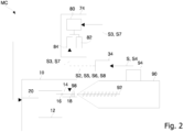
- the system MC of fig. 2 comprises the mold 10 of fig. 1 with a similar installation on board, the same press 90 and the same unit 74.
- the system MC also comprises an electronic control unit 34, which is external to the press 90 and connected via signal lines to the press 90, to the electronic control unit 80 and to an actuator 98 of the shutter 18 mounted in the mould 10.
- One or each signal line may be e.g. an electrical signal cable, a data bus or a wireless channel.
- the electronic control unit 34 is configured to wait for the signal S from the press 90 and then generate and send in sequence signals S2, S5, S6, S8 to the actuator 98 and signals S3, S7 to the electronic control unit 80.
- the signal S generated by the press 90 is e.g. indicative of the start of the injection of molten material or of the state of the means 92, e.g. the position of the injection screw.
- the line carrying the signals S3, S7 may be connected to the control unit 80 or to the means 84, see option in dashed line.
- the electronic control unit 34 is configured to command the electronic control unit 80 to activate or stop the injector 20 via the signal S3, S7 respectively.
- an injection cycle has the following steps:
- the mold can also have multiple cavities, with different shapes, sizes and thicknesses (called family molds ) . Each cavity requires different injection settings and adjustments.
- the unit 74 can be simplified by eliminating the means 82 since they are not used.
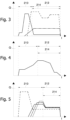
- Figs. 3-5 Shown in Figs. 3-5 are some examples of position/time graphs for the position of various shutters 18 during the injection cycle. The profiles for the different shutters are distinguishable by the type of line stroke.
- the end of the opening stroke of a shutter 18 (nozzle completely open) is indicated by Q, the abscissae axis corresponds to the zero position (nozzle completely closed).
- the phase of opening the shutters 18 and filling of the mold 10 with molten material is the interval 210, while the phase of closing the shutters 18 and packing of the molten material is the interval 212.
- the dynamics of the opening phase is known, where the shutter 18 can be moved in different ways, with different speeds, with pauses, accelerations and decelerations.
- the closing and packing phase also shows different modes of movement of the shutter with variations in speed, accelerations, decelerations, pauses.
- the injector 20 is activated in the push-back phase (denoted by 214), which occurs at any time during the injection process as long as there is molten material in the cavity 12. Generally this coincides approximately with the beginning of the interval 212. Note the difference with the system 100.
- the unit 74 can perform the opening and closing phases of a shutter 18 with just one movement, therefore also in the push back phase 214.
- the system MC instead allows that during the push back phase the shutters are characterized by speed variations, accelerations, decelerations, pauses.
- the use of such a management of the shutters during the push back phase allows advantageously exploiting the braking action of the molten material, present in the cavity 12 and/or in the hot runner 14, imposed on the injected fluid.
Landscapes
- Engineering & Computer Science (AREA)
- Manufacturing & Machinery (AREA)
- Mechanical Engineering (AREA)
- Injection Moulding Of Plastics Or The Like (AREA)
- Moulds For Moulding Plastics Or The Like (AREA)
Applications Claiming Priority (1)
| Application Number | Priority Date | Filing Date | Title |
|---|---|---|---|
| IT202300027903 | 2023-12-22 |
Publications (1)
| Publication Number | Publication Date |
|---|---|
| EP4574391A1 true EP4574391A1 (fr) | 2025-06-25 |
Family
ID=90124058
Family Applications (1)
| Application Number | Title | Priority Date | Filing Date |
|---|---|---|---|
| EP24221892.3A Pending EP4574391A1 (fr) | 2023-12-22 | 2024-12-19 | Système et procédé de moulage par injection |
Country Status (3)
| Country | Link |
|---|---|
| US (1) | US20250205947A1 (fr) |
| EP (1) | EP4574391A1 (fr) |
| CN (1) | CN120190987A (fr) |
Citations (5)
| Publication number | Priority date | Publication date | Assignee | Title |
|---|---|---|---|---|
| DE10253731A1 (de) * | 2002-11-19 | 2004-06-03 | Reum Gmbh & Co. Betriebs Kg | Verfahren zur Herstellung von Kunststoffbauteilen und Mehrfachwerkzeug zur Herstellung von Kunststoffbauteilen |
| DE102006048788A1 (de) | 2006-10-12 | 2008-04-17 | Friedrich Westphal | Verfahren und Vorrichtung zur Herstellung eines einen Hohlraum aufweisenden Bauteils aus Kuststoff |
| WO2012074879A1 (fr) | 2010-11-23 | 2012-06-07 | Synventive Molding Solutions, Inc. | Appareil et procédé de régulation de débit pour moulage par injection |
| EP2265425B1 (fr) * | 2008-03-11 | 2017-11-29 | Basf Se | Procédé et dispositif de moulage par injection de pièces moulées creuses en matière plastique |
| WO2018020177A1 (fr) | 2016-07-28 | 2018-02-01 | Runipsys Europe | Système de commande d'un obturateur d'un système d'injection de matière plastique |
-
2024
- 2024-12-19 EP EP24221892.3A patent/EP4574391A1/fr active Pending
- 2024-12-19 US US18/987,368 patent/US20250205947A1/en active Pending
- 2024-12-20 CN CN202411888983.7A patent/CN120190987A/zh active Pending
Patent Citations (6)
| Publication number | Priority date | Publication date | Assignee | Title |
|---|---|---|---|---|
| DE10253731A1 (de) * | 2002-11-19 | 2004-06-03 | Reum Gmbh & Co. Betriebs Kg | Verfahren zur Herstellung von Kunststoffbauteilen und Mehrfachwerkzeug zur Herstellung von Kunststoffbauteilen |
| DE102006048788A1 (de) | 2006-10-12 | 2008-04-17 | Friedrich Westphal | Verfahren und Vorrichtung zur Herstellung eines einen Hohlraum aufweisenden Bauteils aus Kuststoff |
| EP2265425B1 (fr) * | 2008-03-11 | 2017-11-29 | Basf Se | Procédé et dispositif de moulage par injection de pièces moulées creuses en matière plastique |
| WO2012074879A1 (fr) | 2010-11-23 | 2012-06-07 | Synventive Molding Solutions, Inc. | Appareil et procédé de régulation de débit pour moulage par injection |
| WO2012087491A1 (fr) | 2010-11-23 | 2012-06-28 | Synventive Molding Solutions, Inc. | Appareil de régulation du débit lors du moulage par injection |
| WO2018020177A1 (fr) | 2016-07-28 | 2018-02-01 | Runipsys Europe | Système de commande d'un obturateur d'un système d'injection de matière plastique |
Also Published As
| Publication number | Publication date |
|---|---|
| US20250205947A1 (en) | 2025-06-26 |
| CN120190987A (zh) | 2025-06-24 |
Similar Documents
| Publication | Publication Date | Title |
|---|---|---|
| US4318874A (en) | Molding apparatus | |
| US4120922A (en) | Method for molding | |
| KR101506921B1 (ko) | 다이캐스트 장치에서의 사출 실린더의 유압 회로 | |
| JP2018176727A (ja) | プラスチック材料の射出成形のための方法、装置、およびプレス | |
| JPH08257736A (ja) | ダイカストマシンの射出制御方法および装置 | |
| EP2950996B1 (fr) | Système permettant de commander la vitesse de fermeture de buses à obturateur | |
| CN100584485C (zh) | 压铸机中的分型剂喷射方法及装置 | |
| JP5381161B2 (ja) | ダイカストマシン及びダイカスト鋳造方法 | |
| KR20070037636A (ko) | 사출 성형 슈팅 포트 쐐기 요소용 장치 및 방법 | |
| JP6791948B2 (ja) | 射出成形機 | |
| CA2582178A1 (fr) | Systeme de moulage sous pression a sections multiples sur glissiere | |
| US11794392B2 (en) | Process and apparatus for injection molding of plastic materials | |
| EP4574391A1 (fr) | Système et procédé de moulage par injection | |
| CN101664988A (zh) | 注射控制装置及注射控制方法 | |
| BR102024026307A2 (pt) | Método e sistema para moldagem por injeção | |
| KR102277106B1 (ko) | 사출성형기의 제어장치 및 방법 | |
| JP4085103B2 (ja) | 保圧切替制御方法 | |
| JP4657251B2 (ja) | ダイカストマシンの制御方法 | |
| JPS63128926A (ja) | 射出成形装置の射出制御方法および装置 | |
| JP6077427B2 (ja) | 射出成形機の制御装置及び制御方法 | |
| JP3225241B2 (ja) | 射出成形機 | |
| JP2026002204A (ja) | 射出成形機の制御装置、射出成形機、及び、射出成形システム | |
| JP2026002205A (ja) | 射出成形機の制御装置、射出成形機、及び、射出成形システム | |
| JPH02274522A (ja) | 射出成形装置の射出制御方法および装置 | |
| JPS6260251B2 (fr) |
Legal Events
| Date | Code | Title | Description |
|---|---|---|---|
| PUAI | Public reference made under article 153(3) epc to a published international application that has entered the european phase |
Free format text: ORIGINAL CODE: 0009012 |
|
| STAA | Information on the status of an ep patent application or granted ep patent |
Free format text: STATUS: THE APPLICATION HAS BEEN PUBLISHED |
|
| AK | Designated contracting states |
Kind code of ref document: A1 Designated state(s): AL AT BE BG CH CY CZ DE DK EE ES FI FR GB GR HR HU IE IS IT LI LT LU LV MC ME MK MT NL NO PL PT RO RS SE SI SK SM TR |
|
| P01 | Opt-out of the competence of the unified patent court (upc) registered |
Free format text: CASE NUMBER: UPC_APP_2652_4574391/2025 Effective date: 20250806 |
|
| STAA | Information on the status of an ep patent application or granted ep patent |
Free format text: STATUS: REQUEST FOR EXAMINATION WAS MADE |
|
| 17P | Request for examination filed |
Effective date: 20251223 |