EP4575331A1 - Structure pour installer une unité intérieure de type plafond - Google Patents
Structure pour installer une unité intérieure de type plafond Download PDFInfo
- Publication number
- EP4575331A1 EP4575331A1 EP23903696.5A EP23903696A EP4575331A1 EP 4575331 A1 EP4575331 A1 EP 4575331A1 EP 23903696 A EP23903696 A EP 23903696A EP 4575331 A1 EP4575331 A1 EP 4575331A1
- Authority
- EP
- European Patent Office
- Prior art keywords
- indoor unit
- installation structure
- ceiling
- opening
- hanger
- Prior art date
- Legal status (The legal status is an assumption and is not a legal conclusion. Google has not performed a legal analysis and makes no representation as to the accuracy of the status listed.)
- Pending
Links
Images


Classifications
-
- F—MECHANICAL ENGINEERING; LIGHTING; HEATING; WEAPONS; BLASTING
- F24—HEATING; RANGES; VENTILATING
- F24F—AIR-CONDITIONING; AIR-HUMIDIFICATION; VENTILATION; USE OF AIR CURRENTS FOR SCREENING
- F24F1/00—Room units for air-conditioning, e.g. separate or self-contained units or units receiving primary air from a central station
- F24F1/0007—Indoor units, e.g. fan coil units
- F24F1/0043—Indoor units, e.g. fan coil units characterised by mounting arrangements
- F24F1/0047—Indoor units, e.g. fan coil units characterised by mounting arrangements mounted in the ceiling or at the ceiling
-
- F—MECHANICAL ENGINEERING; LIGHTING; HEATING; WEAPONS; BLASTING
- F24—HEATING; RANGES; VENTILATING
- F24F—AIR-CONDITIONING; AIR-HUMIDIFICATION; VENTILATION; USE OF AIR CURRENTS FOR SCREENING
- F24F13/00—Details common to, or for air-conditioning, air-humidification, ventilation or use of air currents for screening
- F24F13/32—Supports for air-conditioning, air-humidification or ventilation units
-
- F—MECHANICAL ENGINEERING; LIGHTING; HEATING; WEAPONS; BLASTING
- F24—HEATING; RANGES; VENTILATING
- F24F—AIR-CONDITIONING; AIR-HUMIDIFICATION; VENTILATION; USE OF AIR CURRENTS FOR SCREENING
- F24F2221/00—Details or features not otherwise provided for
- F24F2221/14—Details or features not otherwise provided for mounted on the ceiling
Definitions
- Various embodiments of the disclosure relate to a structure for installing a ceiling-type indoor unit.
- a ceiling-fixed indoor unit may be installed by fixing the indoor unit in the inner space of the ceiling above the ceiling surface by means of full-threaded bolts fixed to the ceiling wall above the ceiling surface and one or more nuts fastened to the full-threaded bolts.
- a sufficient working space is required to fasten the full-threaded bolts and the nuts and adjust the fastening height.
- it is not easy to secure a sufficient working space in a narrow space inside the ceiling and the space limitation makes it difficult to install the indoor.
- Various embodiments of the disclosure may reduce installation difficulty by installing a ceiling-mounted indoor unit using a predetermined working space without significant efforts.
- the installation structure may be disposed to overlap a portion of the indoor unit when viewed from thereabove in a state in which the indoor unit may be installed.
- the hanger member may include a through portion configured to allow a full-threaded bolt fixed to the ceiling wall to pass therethrough.
- a plurality of installation structures may be disposed in each corner of an opening of the ceiling surface where the indoor unit is positioned.
- FIG. 1 is a view illustrating a state in which an indoor unit of an air conditioner is installed on a ceiling by an installation structure according to an embodiment.
- the indoor unit 1 of the air conditioner may be installed hung to the ceiling inside a building.
- the indoor unit 1 may be installed by an installation structure 100 pre-installed in the space where the indoor unit 1 is to be installed.
- the indoor unit 1 may be installed on the ceiling, e.g., by mounting or coupling the body 2 to the installation structure 100.
- the installation structure 100 may be installed on the ceiling, e.g., by being coupled to full-threaded bolts 3 fixed to the ceiling wall.
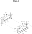
- a plurality of installation structures 100 in which the hanger member 110 and the lower member 120 are coupled may be installed to mount the indoor unit 1, but the disclosure is not limited thereto.
- the ceiling surface C may form an opening O.
- the shape of the opening O may be substantially rectangular, but is not limited thereto.
- the lower member 120 of the installation structure 100 may be disposed adjacent to the opening O. For example, some of the edges of the opening O may contact the lower member 120.
- the ceiling surface C may be disposed to be spaced apart from the ceiling wall (e.g., the ceiling wall W of FIG. 4 ) by a predetermined distance.
- the indoor unit 1 may be installed so that a vent for cooling or heating is positioned in the opening O of the ceiling surface C.
- the worker may install the indoor unit 1 by mounting the indoor unit 1 on the installation structure 100, so the worker may install the indoor unit 1 more conveniently by eliminating the need for coupling with fastening members (e.g., full-threaded bolts and nuts) in a state in which the heavy indoor unit is held between the ceiling wall and the ceiling surface according to the conventional installation method.
- fastening members e.g., full-threaded bolts and nuts
- the lower member 120 may be configured so that a portion of the lower member 120 is inserted into the insertion space defined by the support surface 114, the first bend portion 115, and the second bend portion 116.
- a portion of the vertical surface 121 of the lower member 120 may be inserted into the insertion space.
- the portion of the vertical surface 121 inserted into the insertion space may be formed to be positioned on the same plane as at least one of the first side surface 111b of the first side portion 110b or the second side surface 111c of the second side portion 110c.
- the height of the lower member 120 may vary according to the external appearance of the indoor unit 1.
- the lower member 120 may have an appropriate height so that the height of the indoor unit 1 may not be separately adjusted when the indoor unit 1 is mounted on the installation structure 100.
- the worker may adjust the height by referring to the position of the edge rib 122.
- the worker may adjust the height of the installation structure 100 so that the edge rib 122 of the lower member 120 contacts the ceiling surface C.
- the size and shape of the installation structure 100 may be manufactured according to the size and shape of the indoor unit 1 to be installed. If the indoor unit 1 is mounted on the installation structure 100 after adjusting the height of the edge rib 122 so as to contact the ceiling surface C, the indoor unit 1 is positioned in a desired area.
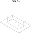
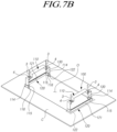
- FIGS. 7A to 7D are views illustrating a process of installing an indoor unit on a ceiling using an installation structure according to an embodiment.
- FIGS. 7A to 7D a state in which the full-threaded bolt 3 is fixed to the ceiling wall is shown, but for convenience of description, the ceiling wall is omitted.
- the full-threaded bolt 3 may be installed at a position corresponding to a position where the indoor unit 1 is to be installed.
- the first full-threaded bolt 3, the second full-threaded bolt 3, the third full-threaded bolt 3, and the fourth full-threaded bolt 3 may be spaced apart from each other and fixed to the ceiling wall.
- An opening O of the ceiling surface C may be formed under the full-threaded bolt 3 to correspond to the size of the plane of the indoor unit 1.
- the worker may fix and couple the first full-threaded bolt 3, the second full-threaded bolt 3, the third full-threaded bolt 3, and the fourth full-threaded bolt 3 through the opening O of the ceiling surface C.
- the number of full-threaded bolts 3 set to install the indoor unit 1 is not limited thereto.
- the installation structure 100 may be installed by being coupled to the full-threaded bolt 3.
- two installation structures 100 may be installed to support two opposite sides of the body of the indoor unit 1, but are not limited thereto.
- one installation structure 100 may be fixed by being coupled to two full-threaded bolts 3, but is not limited thereto, and one installation structure 100 may be configured to be coupled to one or three or more full-threaded bolts 3.
- the worker may install the edge rib of the lower member 120 (e.g., the edge rib 122 of FIG. 2 ) to contact the lower surface of the ceiling surface C.
- the other side portion which is the remaining portion, may also be inserted into the installation structure 100 to fix the indoor unit 1 to the ceiling.
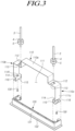
- the worker may finish the installation work by fixing the indoor unit 1 supported on the support surface 114 of the installation structure 100 using a fixing member 130 (or a fastening member).
- an opening O' should be formed which has an area of the area the plane M' of the indoor unit 1 plus the portion where the hanger 810 and the full-threaded bolt 820 are coupled.
- the first length L1' of the opening O' e.g., the length of the long side of the opening O'
- the second length L2' e.g., the length of the long side of the indoor unit 1
- the installation structure 100 may be disposed to overlap a portion of the indoor unit when viewed from above in a state in which the indoor unit 1 is installed.
- the first length L1 (e.g., the length of the long side of the opening O) of the opening O may be equal to or shorter than the second length L2 (e.g., the length of the long side of the indoor unit 1) parallel to the first length L1 in the area occupied by the plane M of the indoor unit 1.
- installation is completed by passing the indoor unit 1 with it inclined, through the opening O and mounting one side on one installation structure 100 and then mounting the other side on another installation structure 100, so that only the opening having the first length L1 shorter than the second length L2 of the indoor unit 1 is formed to install the indoor unit 1 on the ceiling.
- the indoor unit 1 may be installed by utilizing the smaller area of the opening O.
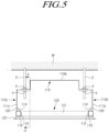
- FIG. 10 is a view illustrating a state in which an installation structure is fixed to a ceiling according to an embodiment.
- FIG. 10 is a view illustrating a state in which an installation structure 1000 is coupled to a full-threaded bolt 3 for convenience of description.
- the installation structure 1000 illustrated in FIG. 10 may be substantially the same as the installation structure 1000 described with reference to FIGS. 1 to 7D .
- the installation structure 1000 may include a hanger member 1010 or a lower member 1020.
- the indoor unit 1 may be installed on the ceiling in a manner to mount the indoor unit 1 on the hanger member 1010 after the installation structure 1000 is coupled to the full-threaded bolt 3 and installed on the ceiling. If the installation structure 1000 is coupled to the full-threaded bolt 3, the lower member 1020 may contact the surroundings of the opening O of the ceiling surface C.
- the hanger member 1010 may be installed to be fixed to a ceiling wall (e.g., the ceiling wall W of FIG. 4 ).
- the hanger member 1010 may be formed of, e.g., a fire-resistant material.
- the hanger member 1010 may include, e.g., a steel or stainless material, but is not limited thereto. Therefore, the installation structure 1000 may be maintained in its shape without being burned or melted by fire, preventing indoor unit 1 from falling even if a fire occurs.
- the hanger member 1010 may include an upper portion 1010a, a first side portion 1010b, and a second side portion 1010c.
- the hanger member 1010 may have a shape with an open lower side.
- the hanger member 1010 may provide a mounting space 1011 in which a portion of the indoor unit 1 is mounted.
- the mounting space 1011 may be defined by the upper portion 1010a, the first side portion 1010b, and the second side portion 1010c.
- the hanger member 1010 may include a through portion (not shown) configured to allow the full-threaded bolt 3 fixed to the ceiling wall W to pass there through.
- the through portion may be positioned, e.g., in the upper portion 1010a of the hanger member 1010.
- the hanger member 1010 may include an insertion portion 1012 provided to be open to allow the full-threaded bolt 3 to be inserted into the through portion when the installation structure 1000 is installed.
- the hanger member 1010 may be configured to mount the indoor unit 1.
- the hanger member 1010 may include a support surface 1014 for mounting or supporting the indoor unit 1.
- the support surface 1014 may be positioned on each of the first side portion 1010b and the second side portion 1010c.
- the support surface 1014 may be positioned under the hanger member 1010 and may extend toward the inside of the hanger member 1010.
- the inside may refer to a direction toward the mounting space 1011.
- the support surface 1014 may extend in, e.g., a horizontal direction.
- the support surface 1014 may extend, e.g., in a direction perpendicular to the first side portion 1010b or the second side portion 1010c.
- the first support surface 1014 formed on the first side portion 1010b and the second support surface 1014 formed on the second side portion 1010c may be positioned at substantially the same height.
- the support surface 1014 may include an opening 1014a.
- the installation structure 1000 may include a fixing member 1030 (or a fastening member).
- the fixing member 1030 may pass through the opening 1014a of the support surface 1014. If the indoor unit 1 is mounted on the support surface 1014, the fixing member 1030 may pass through the opening 1014a of the support surface 1014 to be fastened to the indoor unit 1. As the fixing member 1030 is fastened to the indoor unit 1, the indoor unit 1 may be fixedly coupled to the installation structure 1000. Therefore, it is possible to prevent the indoor unit 1 from moving with respect to the installation structure 1000 due to vibration generated while the indoor unit 1 is operating.
- the lower member 1020 may include a vertical surface 1021 and an edge rib 1022.
- the edge rib 1022 may horizontally extend outward from the vertical surface 1021.
- the edge rib 1022 may extend from at least a portion of a lower end of the vertical surface 1021, but is not limited thereto, may extend from another portion of the vertical surface 1021.
- the edge rib 1022 may be a portion in contact with the ceiling surface C when the installation structure 1000 is coupled to the full-threaded bolt 3.
- the installation structure 1000 may be installed so that the edge rib 1022 faces the ceiling surface C.
- the lower member 1020 may be formed to contact the edge of the opening O of the ceiling surface C for positioning the indoor unit 1.
- the vertical surface 1021 of the lower member 1020 may be formed to contact the edge of the opening O of the ceiling surface C.
- the lower member 1020 may have, e.g., the same shape as the opening O of the ceiling surface C.
- the lower member 1020 may have a rectangular cross-sectional shape corresponding to the opening O of the ceiling surface C as illustrated.
- the vertical surface 1021 of the lower member 1020 may have the same shape as the opening O of the ceiling surface C.
- the edge rib 1022 may be configured to be visible when viewed from below the ceiling surface C.
- the edge rib 1022 may contact the lower surface of the ceiling surface C, for example.
- the edge rib 1022 may support the ceiling surface C.
- the shape of the edge rib 1022 is not limited to the foregoing, and may be configured to be invisible when viewed from below the ceiling surface C. In this case, the edge rib 1022 may contact the upper surface of the ceiling surface C.
- FIG. 11 is a view illustrating a state in which an installation structure is fixed to a ceiling according to an embodiment.
- FIG. 11 is a view illustrating a state in which an installation structure 1100 is coupled to a full-threaded bolt 3 for convenience of description.
- the installation structure 1100 may include a hanger member 1110 or a lower member 1120.
- the indoor unit 1 may be installed on the ceiling in a manner to mount the indoor unit 1 on the hanger member 1110 after the installation structure 1100 is coupled to the full-threaded bolt 3 and installed on the ceiling. If the installation structure 1100 is coupled to the full-threaded bolt 3, the lower member 1120 may contact the surroundings of the opening O of the ceiling surface C.
- Each installation structure 1100 may be disposed by being coupled to one full-threaded bolt 3, for example.
- installation structures 1100 as many installation structures 1100 as the number of full-threaded bolts fixed to the ceiling wall (e.g., the ceiling wall W of FIG. 4 ) may be provided.
- the ceiling wall W of FIG. 4 e.g., the ceiling wall W of FIG. 4
- four installation structures 1100 may be provided as illustrated.
- Each installation structure 1100 may be positioned at a corner portion of the opening O of the ceiling surface C.
- the hanger member 1110 may be installed to be fixed to the ceiling wall W.
- the hanger member 1110 may be formed of, e.g., a fire-resistant material.
- the hanger member 1110 may include, e.g., a steel or stainless material, but is not limited thereto. Therefore, the installation structure 1100 may be maintained in its shape without being burned or melted by fire, preventing indoor unit 1 from falling even if a fire occurs.
- the hanger member 1110 may include an upper surface 1110a, a first side surface 1110b, and a second side surface 1110c perpendicular to the first side surface 1110b.
- the upper surface 1110a may be, e.g., a portion coupled to the full-threaded bolt 3.
- the first side surface 1110b and the second side surface 1110c may extend to be perpendicular from the upper surface 1110a to be coupled to the lower member 1120.
- the hanger member 1110 may include a through portion (not shown) configured to allow the full-threaded bolt 3 fixed to the ceiling wall W to pass therethrough.
- the through portion may be positioned, e.g., on the upper surface 1110a of the hanger member 1110.
- the hanger member 1110 may include an insertion portion 1112 provided to be open to allow the full-threaded bolt 3 to be inserted into the through portion when the installation structure 1100 is installed.
- the insertion portion 1112 may be formed to extend along a portion of the upper surface 1110a and the first side surface 1110b, for example. In other words, the first side surface 1110b may be formed to be partially open. Due to the open shape, when the full-threaded bolt 3 is inserted laterally into the hanger member 1110, it may be inserted more conveniently.
- the hanger member 1110 may be configured to mount the indoor unit 1.
- the hanger member 1110 may include a support surface 1114 for mounting or supporting the indoor unit 1.
- the support surface 1114 may be formed to extend from the second side surface 1110c.
- the support surface 1114 may be positioned under the hanger member 1110 and may extend toward the inside of the hanger member 1110.
- the inside may refer to a direction toward the indoor unit (e.g., the indoor unit 1 of FIG. 1 ).
- the support surface 1114 may extend in, e.g., a horizontal direction.
- the support surface 1114 may extend in a direction perpendicular to the second side surface 1110c, for example.
- the support surface 1114 may include an opening 1114a.
- the installation structure 1100 may include a fixing member 1130 (or a fastening member).
- the fixing member 1130 may pass through the opening 1114a of the support surface 1114. If the indoor unit 1 is mounted on the support surface 1114, the fixing member 1130 may pass through the opening 1114a of the support surface 1114 to be fastened to the indoor unit 1. As the fixing member 1130 is fastened to the indoor unit 1, the indoor unit 1 may be fixedly coupled to the installation structure 1100. Therefore, it is possible to prevent the indoor unit 1 from moving with respect to the installation structure 1100 due to vibration generated while the indoor unit 1 is operating.
- the lower member 1120 may be coupled to a lower portion of the hanger member 1110.
- the lower member 1120 may be coupled to the hanger member 1110 by, e.g., a fixing member 1130 (or a fastening member).
- the lower member 1120 may be manufactured by an injection method.
- the lower member 1120 may be formed of, e.g., a plastic material, but is not limited thereto.
- the lower member 1120 may include a vertical surface 1121 and an edge rib 1122.
- the edge rib 1122 may horizontally extend outward from the vertical surface 1121.
- the edge rib 1122 may extend from at least a portion of a lower end of the vertical surface 1121, but is not limited thereto, may extend from another portion of the vertical surface 1121.
- the edge rib 1122 may be a portion in contact with the ceiling surface C when the installation structure 1100 is coupled to the full-threaded bolt 3.
- the installation structure 1100 may be installed so that the edge rib 1122 faces the ceiling surface C.
- the lower member 1120 may be formed to contact the edge of the opening O of the ceiling surface C for positioning the indoor unit 1.
- the vertical surface 1121 of the lower member 1120 may be formed to contact the edge of the opening O of the ceiling surface C.
- the lower member 1120 may have, e.g., the same shape as the opening O of the ceiling surface C.
- the lower member 1120 may have a rectangular cross-sectional shape corresponding to the opening O of the ceiling surface C as illustrated.
- the vertical surface 1121 of the lower member 1120 may have the same shape as the opening O of the ceiling surface C.
- a plurality of hanger members 1110 may be coupled to the lower member 1120.
- two hanger members 1110 may be coupled on two opposite sides of the lower member 1120 formed to surround the edge of the opening O of the ceiling surface C.
- the number of hanger members 1110 coupled to the lower member 1120 is not limited thereto, and three or more hanger members 1110 may be coupled to the lower member 1120.
- the edge rib 1122 may be configured to be visible when viewed from below the ceiling surface C.
- the edge rib 1122 may contact the lower surface of the ceiling surface C, for example.
- the edge rib 1122 may support the ceiling surface C.
- the shape of the edge rib 1122 is not limited to the foregoing, and may be configured to be invisible when viewed from below the ceiling surface C. In this case, the edge rib 1122 may contact the upper surface of the ceiling surface C.
- each of such phrases as “A or B,” “at least one of A and B,” “at least one of A or B,” “A, B, or C,” “at least one of A, B, and C,” and “at least one of A, B, or C,” may include all possible combinations of the items enumerated together in a corresponding one of the phrases.
- the term 'and/or' should be understood as encompassing any and all possible combinations by one or more of the enumerated items.
- the terms “include,” “have,” and “comprise” are used merely to designate the presence of the feature, component, part, or a combination thereof described herein, but use of the term does not exclude the likelihood of presence or adding one or more other features, components, parts, or combinations thereof.
- the terms “first” and “second” may modify various components regardless of importance and/or order and are used to distinguish a component from another without limiting the components.
- the terms “configured to” may be interchangeably used with the terms “suitable for,” “having the capacity to,” “designed to,” “adapted to,” “made to,” or “capable of” depending on circumstances.
- the term “configured to” does not essentially mean “specifically designed in hardware to.” Rather, the term “configured to” may mean that a device can perform an operation together with another device or parts.
- a 'device configured (or set) to perform A, B, and C' may be a dedicated device to perform the corresponding operation or may mean a general-purpose device capable of various operations including the corresponding operation.
Landscapes
- Engineering & Computer Science (AREA)
- Chemical & Material Sciences (AREA)
- Combustion & Propulsion (AREA)
- Mechanical Engineering (AREA)
- General Engineering & Computer Science (AREA)
- Connection Of Plates (AREA)
- Residential Or Office Buildings (AREA)
Applications Claiming Priority (2)
| Application Number | Priority Date | Filing Date | Title |
|---|---|---|---|
| KR1020220173826A KR20240090073A (ko) | 2022-12-13 | 2022-12-13 | 천장형 실내기 설치 구조 |
| PCT/KR2023/014901 WO2024128492A1 (fr) | 2022-12-13 | 2023-09-26 | Structure pour installer une unité intérieure de type plafond |
Publications (2)
| Publication Number | Publication Date |
|---|---|
| EP4575331A1 true EP4575331A1 (fr) | 2025-06-25 |
| EP4575331A4 EP4575331A4 (fr) | 2026-03-18 |
Family
ID=91485107
Family Applications (1)
| Application Number | Title | Priority Date | Filing Date |
|---|---|---|---|
| EP23903696.5A Pending EP4575331A4 (fr) | 2022-12-13 | 2023-09-26 | Structure pour installer une unité intérieure de type plafond |
Country Status (4)
| Country | Link |
|---|---|
| US (1) | US20250230952A1 (fr) |
| EP (1) | EP4575331A4 (fr) |
| KR (1) | KR20240090073A (fr) |
| WO (1) | WO2024128492A1 (fr) |
Family Cites Families (8)
| Publication number | Priority date | Publication date | Assignee | Title |
|---|---|---|---|---|
| JPH1019309A (ja) * | 1996-07-01 | 1998-01-23 | Nemii Kogyo Kk | 組立式多目的架台 |
| KR100360423B1 (ko) * | 2000-04-29 | 2002-11-08 | 주식회사 엘지이아이 | 천정카세트형 공기조화기 |
| KR20050039975A (ko) * | 2003-10-27 | 2005-05-03 | 엘지전자 주식회사 | 덕트형 공기조화기의 실내기에서 캐비닛의 고정구조 |
| JP4297819B2 (ja) * | 2004-03-30 | 2009-07-15 | 三洋電機株式会社 | 天井埋込型空気調和装置 |
| KR101355402B1 (ko) * | 2011-11-28 | 2014-01-28 | 주식회사 힘펠 | 토출관 기반의 환풍기 설치장치 및 이를 이용한 환풍기 설치 방법 |
| KR101861104B1 (ko) * | 2017-09-28 | 2018-06-29 | (주)센도리 | 승하강식 공기순환기 |
| CN108443998A (zh) * | 2018-02-08 | 2018-08-24 | 北京中科纳清科技股份有限公司 | 一种嵌入式空气净化装置、空气净化系统及新风净化系统 |
| KR102369362B1 (ko) * | 2019-12-27 | 2022-03-04 | 대륙종합건설 주식회사 | 실내 천장용 친환경 마감 구조물 |
-
2022
- 2022-12-13 KR KR1020220173826A patent/KR20240090073A/ko active Pending
-
2023
- 2023-09-26 WO PCT/KR2023/014901 patent/WO2024128492A1/fr not_active Ceased
- 2023-09-26 EP EP23903696.5A patent/EP4575331A4/fr active Pending
-
2025
- 2025-04-03 US US19/169,634 patent/US20250230952A1/en active Pending
Also Published As
| Publication number | Publication date |
|---|---|
| KR20240090073A (ko) | 2024-06-21 |
| EP4575331A4 (fr) | 2026-03-18 |
| US20250230952A1 (en) | 2025-07-17 |
| WO2024128492A1 (fr) | 2024-06-20 |
Similar Documents
| Publication | Publication Date | Title |
|---|---|---|
| US7654495B2 (en) | Hanger assembly | |
| KR100349978B1 (ko) | 창문형 공기조화기 | |
| AU2017202673B2 (en) | Unit attaching device and indoor unit | |
| KR101470537B1 (ko) | 공기조화기 | |
| US20150176856A1 (en) | Indoor unit and air-conditioning apparatus | |
| EP4575331A1 (fr) | Structure pour installer une unité intérieure de type plafond | |
| EP3091304B1 (fr) | Climatiseur | |
| JP3080086B2 (ja) | 空気調和機の据付具及び据付構造 | |
| JP3267599B2 (ja) | 空調機器の室内機固定装置 | |
| JP3756395B2 (ja) | 天井装着式空調機 | |
| JP7843874B2 (ja) | 仮掛け構造、室内機、および空気調和機 | |
| KR102490944B1 (ko) | 공기 조화기 | |
| KR20090129198A (ko) | 공기조화기의 실외기 | |
| US20250216094A1 (en) | Clip member and installation structure including same | |
| JP2013096649A (ja) | 空調機器の脱落防止金具 | |
| JP2000274808A (ja) | 天井埋込型空気調和機 | |
| JPH0440113Y2 (fr) | ||
| JP6952912B2 (ja) | 化粧パネル及び室内機 | |
| WO2024111046A1 (fr) | Unité d'intérieur de climatiseur | |
| KR200300019Y1 (ko) | 벽걸이형 에어콘의 걸림구조 | |
| JPH112426A (ja) | 空調用室内機 | |
| JP2597218Y2 (ja) | 空調機グリル取付構造 | |
| JP3208950B2 (ja) | クーリングユニットの取付構造 | |
| KR20050060559A (ko) | 공기조화기 | |
| KR980009019U (ko) | 분리형 공기조화기의 실내기 설치대 |
Legal Events
| Date | Code | Title | Description |
|---|---|---|---|
| STAA | Information on the status of an ep patent application or granted ep patent |
Free format text: STATUS: THE INTERNATIONAL PUBLICATION HAS BEEN MADE |
|
| PUAI | Public reference made under article 153(3) epc to a published international application that has entered the european phase |
Free format text: ORIGINAL CODE: 0009012 |
|
| STAA | Information on the status of an ep patent application or granted ep patent |
Free format text: STATUS: REQUEST FOR EXAMINATION WAS MADE |
|
| 17P | Request for examination filed |
Effective date: 20250321 |
|
| AK | Designated contracting states |
Kind code of ref document: A1 Designated state(s): AL AT BE BG CH CY CZ DE DK EE ES FI FR GB GR HR HU IE IS IT LI LT LU LV MC ME MK MT NL NO PL PT RO RS SE SI SK SM TR |
|
| A4 | Supplementary search report drawn up and despatched |
Effective date: 20260213 |
|
| RIC1 | Information provided on ipc code assigned before grant |
Ipc: F24F 1/0047 20190101AFI20260209BHEP Ipc: F24F 13/32 20060101ALI20260209BHEP |
|
| DAV | Request for validation of the european patent (deleted) | ||
| DAX | Request for extension of the european patent (deleted) |