JP2006104792A - 鉄筋篭 - Google Patents
鉄筋篭 Download PDFInfo
- Publication number
- JP2006104792A JP2006104792A JP2004293672A JP2004293672A JP2006104792A JP 2006104792 A JP2006104792 A JP 2006104792A JP 2004293672 A JP2004293672 A JP 2004293672A JP 2004293672 A JP2004293672 A JP 2004293672A JP 2006104792 A JP2006104792 A JP 2006104792A
- Authority
- JP
- Japan
- Prior art keywords
- vertical
- bars
- horizontal
- reinforcements
- assembly
- Prior art date
- Legal status (The legal status is an assumption and is not a legal conclusion. Google has not performed a legal analysis and makes no representation as to the accuracy of the status listed.)
- Granted
Links
- 230000000712 assembly Effects 0.000 claims abstract description 17
- 238000000429 assembly Methods 0.000 claims abstract description 17
- 230000003014 reinforcing effect Effects 0.000 claims description 24
- 229910000831 Steel Inorganic materials 0.000 claims description 2
- 239000010959 steel Substances 0.000 claims description 2
- 230000002787 reinforcement Effects 0.000 abstract description 25
- 238000003466 welding Methods 0.000 abstract description 4
- 238000000034 method Methods 0.000 description 8
- 239000004567 concrete Substances 0.000 description 3
- 239000011150 reinforced concrete Substances 0.000 description 3
- 229910001294 Reinforcing steel Inorganic materials 0.000 description 2
- 238000013459 approach Methods 0.000 description 1
- 210000001217 buttock Anatomy 0.000 description 1
- 230000000694 effects Effects 0.000 description 1
Images
Landscapes
- Reinforcement Elements For Buildings (AREA)
Abstract
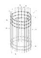
【解決手段】 直線状の縦筋と、円弧状の横筋とを縦横に組んだ少なくとも3個の円弧面状の組立体を形成し、各組立体を構成する横筋の一方の端部には隣接する組立体の他方の端部の縦筋に係合する鉤部を形成し、これら鉤部をそれぞれ縦筋に係合させて組立体を円筒状にした後に、複数のループ筋を円筒状の内側に配設して固定する組立式の鉄筋篭であって、前記縦筋は、該縦筋の上部または下部の端部寄りに配設する二本の横筋とのそれぞれの交点を溶接して接合し、他の横筋とのそれぞれの交点を結束して係止することにより、地震等の振動に対して、縦筋と横筋とにおける係止が不完全な状態にならないようにできると共に、縦筋と横筋とを係止させる際に、これら縦筋と横筋とが歪んだ状態にならないようにできるようになる。
【選択図】図1
Description
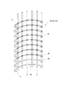
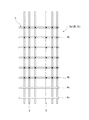
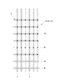
本発明の実施の形態に係る鉄筋篭1の略示的な斜視図を図1に示し、該鉄筋篭1を構成する組立体2a、2b、2cのうち1つの組立体2aを略示的に示した斜視図を図2に示し、その平面図を図3に示す。なお、組立体2a、2b、2cにおいては、いずれも同様の構成であるため、代表して組立体2aを用いて説明し、組立体2b、2cについては説明を省略する。
2a、2b、2c 組立体
3 縦筋
4a、4b 横筋
5 鉤部
Claims (1)
- 直線状の縦筋と、円弧状の横筋とを縦横に組んだ少なくとも3個の円弧面状の組立体を形成し、各組立体を構成する横筋の一方の端部には隣接する組立体の他方の端部の縦筋に係合する鉤部を形成し、これら鉤部をそれぞれ縦筋に係合させて組立体を円筒状にした後に、複数のループ筋を円筒状の内側に配設して固定する組立式の鉄筋篭であって、
前記縦筋は、該縦筋の上部または下部の端部寄りに配設する二本の横筋とのそれぞれの交点を溶接して接合し、他の横筋とのそれぞれの交点を結束して係止すること
を特徴とする鉄筋篭。
Priority Applications (1)
| Application Number | Priority Date | Filing Date | Title |
|---|---|---|---|
| JP2004293672A JP4235596B2 (ja) | 2004-10-06 | 2004-10-06 | 鉄筋篭 |
Applications Claiming Priority (1)
| Application Number | Priority Date | Filing Date | Title |
|---|---|---|---|
| JP2004293672A JP4235596B2 (ja) | 2004-10-06 | 2004-10-06 | 鉄筋篭 |
Publications (2)
| Publication Number | Publication Date |
|---|---|
| JP2006104792A true JP2006104792A (ja) | 2006-04-20 |
| JP4235596B2 JP4235596B2 (ja) | 2009-03-11 |
Family
ID=36374843
Family Applications (1)
| Application Number | Title | Priority Date | Filing Date |
|---|---|---|---|
| JP2004293672A Expired - Fee Related JP4235596B2 (ja) | 2004-10-06 | 2004-10-06 | 鉄筋篭 |
Country Status (1)
| Country | Link |
|---|---|
| JP (1) | JP4235596B2 (ja) |
Citations (4)
| Publication number | Priority date | Publication date | Assignee | Title |
|---|---|---|---|---|
| JPH0420054B2 (ja) * | 1984-04-03 | 1992-03-31 | Hiroshi Suwa | |
| JPH0644856U (ja) * | 1992-03-02 | 1994-06-14 | 有限会社西山鉄網製作所 | 建築用鉄筋ユニット |
| JPH09177247A (ja) * | 1995-12-25 | 1997-07-08 | Takenaka Komuten Co Ltd | 場所打ち杭の鉄筋籠ユニット化工法 |
| JP3313145B2 (ja) * | 1992-07-17 | 2002-08-12 | 林精工株式会社 | 円筒状鉄筋組立枠 |
-
2004
- 2004-10-06 JP JP2004293672A patent/JP4235596B2/ja not_active Expired - Fee Related
Patent Citations (4)
| Publication number | Priority date | Publication date | Assignee | Title |
|---|---|---|---|---|
| JPH0420054B2 (ja) * | 1984-04-03 | 1992-03-31 | Hiroshi Suwa | |
| JPH0644856U (ja) * | 1992-03-02 | 1994-06-14 | 有限会社西山鉄網製作所 | 建築用鉄筋ユニット |
| JP3313145B2 (ja) * | 1992-07-17 | 2002-08-12 | 林精工株式会社 | 円筒状鉄筋組立枠 |
| JPH09177247A (ja) * | 1995-12-25 | 1997-07-08 | Takenaka Komuten Co Ltd | 場所打ち杭の鉄筋籠ユニット化工法 |
Also Published As
| Publication number | Publication date |
|---|---|
| JP4235596B2 (ja) | 2009-03-11 |
Similar Documents
| Publication | Publication Date | Title |
|---|---|---|
| JP2010084490A (ja) | 鉄筋籠およびその製造方法、並びに鉄筋籠用半体およびその製造方法 | |
| JP4712021B2 (ja) | 鉄筋コンクリート構造物中の配筋に用いる補強鉄筋及び配筋構造 | |
| TWI694199B (zh) | 鋼筋籠及鋼筋籠之形狀回復方法 | |
| JP2018076653A (ja) | W壁構築工法とw壁構造体、w壁用のプレキャストコンクリート板と型枠支持治具 | |
| JP5035984B2 (ja) | プレキャスト床版と梁との接合構造 | |
| JP6428027B2 (ja) | 柱鉄筋接続パネルおよび鉄筋構造物 | |
| JP2020063617A (ja) | プレキャストコンクリート部材の継手構造 | |
| JP3272530B2 (ja) | 鉄筋コンクリート有孔梁用の貫通孔上下部補強金物 | |
| JP5346244B2 (ja) | 場所打ちコンクリート杭用鉄筋籠の組立方法及び分割鉄筋籠組立装置 | |
| JP4235596B2 (ja) | 鉄筋篭 | |
| JP2019203239A (ja) | 柱梁接合構造 | |
| JP7370577B2 (ja) | 鉄筋コンクリート有孔梁の補強金具及び補強構造 | |
| JP6262459B2 (ja) | 鉄筋ユニット及び鉄筋コンクリート構造 | |
| JP7483569B2 (ja) | 柱の外殻PCa部材片及び柱の外殻PCa部材 | |
| JP5780829B2 (ja) | 鉄筋コンクリート構造物における配筋構造および配筋方法 | |
| JP2020002715A (ja) | 組立構造体、当該組立構造体の組立て方法、及び構造体 | |
| JP2000136597A5 (ja) | ||
| KR102922146B1 (ko) | 전단철물을 이용한 복합구조의 흙막이벽체 엄지말뚝 | |
| JP2008208605A (ja) | ユニット鉄筋の連結方法 | |
| JP7291001B2 (ja) | ブレース構造 | |
| JP4298678B2 (ja) | 接続構造 | |
| JPH0633601A (ja) | 円筒状鉄筋組立枠 | |
| JP7158997B2 (ja) | プレキャストコンクリート部材の接合構造および接合方法 | |
| JP6879634B2 (ja) | プレキャスト梁部材の接合構造及び接合方法 | |
| JP2813264B2 (ja) | 鉄筋コンクリート柱の剪断補強方法 |
Legal Events
| Date | Code | Title | Description |
|---|---|---|---|
| A621 | Written request for application examination |
Free format text: JAPANESE INTERMEDIATE CODE: A621 Effective date: 20060713 |
|
| A977 | Report on retrieval |
Free format text: JAPANESE INTERMEDIATE CODE: A971007 Effective date: 20081113 |
|
| TRDD | Decision of grant or rejection written | ||
| A01 | Written decision to grant a patent or to grant a registration (utility model) |
Free format text: JAPANESE INTERMEDIATE CODE: A01 Effective date: 20081125 |
|
| A01 | Written decision to grant a patent or to grant a registration (utility model) |
Free format text: JAPANESE INTERMEDIATE CODE: A01 |
|
| A61 | First payment of annual fees (during grant procedure) |
Free format text: JAPANESE INTERMEDIATE CODE: A61 Effective date: 20081215 |
|
| FPAY | Renewal fee payment (event date is renewal date of database) |
Free format text: PAYMENT UNTIL: 20111219 Year of fee payment: 3 |
|
| R150 | Certificate of patent or registration of utility model |
Ref document number: 4235596 Country of ref document: JP Free format text: JAPANESE INTERMEDIATE CODE: R150 Free format text: JAPANESE INTERMEDIATE CODE: R150 |
|
| FPAY | Renewal fee payment (event date is renewal date of database) |
Free format text: PAYMENT UNTIL: 20121219 Year of fee payment: 4 |
|
| R250 | Receipt of annual fees |
Free format text: JAPANESE INTERMEDIATE CODE: R250 |
|
| FPAY | Renewal fee payment (event date is renewal date of database) |
Free format text: PAYMENT UNTIL: 20131219 Year of fee payment: 5 |
|
| R250 | Receipt of annual fees |
Free format text: JAPANESE INTERMEDIATE CODE: R250 |
|
| R250 | Receipt of annual fees |
Free format text: JAPANESE INTERMEDIATE CODE: R250 |
|
| R250 | Receipt of annual fees |
Free format text: JAPANESE INTERMEDIATE CODE: R250 |
|
| R250 | Receipt of annual fees |
Free format text: JAPANESE INTERMEDIATE CODE: R250 |
|
| R250 | Receipt of annual fees |
Free format text: JAPANESE INTERMEDIATE CODE: R250 |
|
| R250 | Receipt of annual fees |
Free format text: JAPANESE INTERMEDIATE CODE: R250 |
|
| R250 | Receipt of annual fees |
Free format text: JAPANESE INTERMEDIATE CODE: R250 |
|
| R250 | Receipt of annual fees |
Free format text: JAPANESE INTERMEDIATE CODE: R250 |
|
| R250 | Receipt of annual fees |
Free format text: JAPANESE INTERMEDIATE CODE: R250 |
|
| LAPS | Cancellation because of no payment of annual fees |