JP2017537277A - 分離油圧カプラ - Google Patents
分離油圧カプラ Download PDFInfo
- Publication number
- JP2017537277A JP2017537277A JP2017519560A JP2017519560A JP2017537277A JP 2017537277 A JP2017537277 A JP 2017537277A JP 2017519560 A JP2017519560 A JP 2017519560A JP 2017519560 A JP2017519560 A JP 2017519560A JP 2017537277 A JP2017537277 A JP 2017537277A
- Authority
- JP
- Japan
- Prior art keywords
- locking member
- coupler
- hydraulic coupler
- hydraulic
- locking
- Prior art date
- Legal status (The legal status is an assumption and is not a legal conclusion. Google has not performed a legal analysis and makes no representation as to the accuracy of the status listed.)
- Granted
Links
Images




Classifications
-
- F—MECHANICAL ENGINEERING; LIGHTING; HEATING; WEAPONS; BLASTING
- F16—ENGINEERING ELEMENTS AND UNITS; GENERAL MEASURES FOR PRODUCING AND MAINTAINING EFFECTIVE FUNCTIONING OF MACHINES OR INSTALLATIONS; THERMAL INSULATION IN GENERAL
- F16K—VALVES; TAPS; COCKS; ACTUATING-FLOATS; DEVICES FOR VENTING OR AERATING
- F16K17/00—Safety valves; Equalising valves, e.g. pressure relief valves
- F16K17/40—Safety valves; Equalising valves, e.g. pressure relief valves with a fracturing member, e.g. fracturing diaphragm, glass, fusible joint
-
- F—MECHANICAL ENGINEERING; LIGHTING; HEATING; WEAPONS; BLASTING
- F16—ENGINEERING ELEMENTS AND UNITS; GENERAL MEASURES FOR PRODUCING AND MAINTAINING EFFECTIVE FUNCTIONING OF MACHINES OR INSTALLATIONS; THERMAL INSULATION IN GENERAL
- F16L—PIPES; JOINTS OR FITTINGS FOR PIPES; SUPPORTS FOR PIPES, CABLES OR PROTECTIVE TUBING; MEANS FOR THERMAL INSULATION IN GENERAL
- F16L27/00—Adjustable joints; Joints allowing movement
- F16L27/08—Adjustable joints; Joints allowing movement allowing adjustment or movement only about the axis of one pipe
- F16L27/0804—Adjustable joints; Joints allowing movement allowing adjustment or movement only about the axis of one pipe the fluid passing axially from one joint element to another
- F16L27/0808—Adjustable joints; Joints allowing movement allowing adjustment or movement only about the axis of one pipe the fluid passing axially from one joint element to another the joint elements extending coaxially for some distance from their point of separation
- F16L27/0824—Adjustable joints; Joints allowing movement allowing adjustment or movement only about the axis of one pipe the fluid passing axially from one joint element to another the joint elements extending coaxially for some distance from their point of separation with ball or roller bearings
- F16L27/0828—Adjustable joints; Joints allowing movement allowing adjustment or movement only about the axis of one pipe the fluid passing axially from one joint element to another the joint elements extending coaxially for some distance from their point of separation with ball or roller bearings having radial bearings
-
- F—MECHANICAL ENGINEERING; LIGHTING; HEATING; WEAPONS; BLASTING
- F16—ENGINEERING ELEMENTS AND UNITS; GENERAL MEASURES FOR PRODUCING AND MAINTAINING EFFECTIVE FUNCTIONING OF MACHINES OR INSTALLATIONS; THERMAL INSULATION IN GENERAL
- F16L—PIPES; JOINTS OR FITTINGS FOR PIPES; SUPPORTS FOR PIPES, CABLES OR PROTECTIVE TUBING; MEANS FOR THERMAL INSULATION IN GENERAL
- F16L37/00—Couplings of the quick-acting type
- F16L37/02—Couplings of the quick-acting type in which the connection is maintained only by friction of the parts being joined
-
- B—PERFORMING OPERATIONS; TRANSPORTING
- B67—OPENING, CLOSING OR CLEANING BOTTLES, JARS OR SIMILAR CONTAINERS; LIQUID HANDLING
- B67D—DISPENSING, DELIVERING OR TRANSFERRING LIQUIDS, NOT OTHERWISE PROVIDED FOR
- B67D7/00—Apparatus or devices for transferring liquids from bulk storage containers or reservoirs into vehicles or into portable containers, e.g. for retail sale purposes
- B67D7/06—Details or accessories
- B67D7/32—Arrangements of safety or warning devices; Means for preventing unauthorised delivery of liquid
- B67D7/3218—Arrangements of safety or warning devices; Means for preventing unauthorised delivery of liquid relating to emergency shut-off means
-
- F—MECHANICAL ENGINEERING; LIGHTING; HEATING; WEAPONS; BLASTING
- F16—ENGINEERING ELEMENTS AND UNITS; GENERAL MEASURES FOR PRODUCING AND MAINTAINING EFFECTIVE FUNCTIONING OF MACHINES OR INSTALLATIONS; THERMAL INSULATION IN GENERAL
- F16L—PIPES; JOINTS OR FITTINGS FOR PIPES; SUPPORTS FOR PIPES, CABLES OR PROTECTIVE TUBING; MEANS FOR THERMAL INSULATION IN GENERAL
- F16L55/00—Devices or appurtenances for use in, or in connection with, pipes or pipe systems
- F16L55/10—Means for stopping flow in pipes or hoses
- F16L55/1015—Couplings closed automatically when disengaging force exceeds preselected value
-
- F—MECHANICAL ENGINEERING; LIGHTING; HEATING; WEAPONS; BLASTING
- F16—ENGINEERING ELEMENTS AND UNITS; GENERAL MEASURES FOR PRODUCING AND MAINTAINING EFFECTIVE FUNCTIONING OF MACHINES OR INSTALLATIONS; THERMAL INSULATION IN GENERAL
- F16L—PIPES; JOINTS OR FITTINGS FOR PIPES; SUPPORTS FOR PIPES, CABLES OR PROTECTIVE TUBING; MEANS FOR THERMAL INSULATION IN GENERAL
- F16L37/00—Couplings of the quick-acting type
- F16L37/22—Couplings of the quick-acting type in which the connection is maintained by means of balls, rollers or helical springs under radial pressure between the parts
- F16L37/23—Couplings of the quick-acting type in which the connection is maintained by means of balls, rollers or helical springs under radial pressure between the parts by means of balls
Landscapes
- Engineering & Computer Science (AREA)
- General Engineering & Computer Science (AREA)
- Mechanical Engineering (AREA)
- Quick-Acting Or Multi-Walled Pipe Joints (AREA)
- Preventing Unauthorised Actuation Of Valves (AREA)
Abstract
Description
Claims (23)
- 流体を形成するために給油栓に取り外し可能に取り付け可能であるカプラ本体アセンブリと、
ロック位置と非ロック位置との間を移動可能な少なくとも1つの第1のロック部材を有する前記カプラ本体アセンブリを備える経路と、
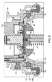
前記カプラ本体アセンブリに連結され、脆弱領域を有する第2のロック部材を含むスリーブアセンブリであって、前記第2のロック部材は、前記少なくとも1つの第1のロック部材をロック位置に移動させ、前記カプラ本体を前記給油栓に取り付けるために、前記少なくとも1つの第1のロック部材と選択的に移動可能に係合し、前記少なくとも1つの第1のロック部材を前記非ロック位置に動かすことができ、前記カプラ本体を前記給油栓から分離させることができるために、前記少なくとも1つの第1のロック部材から移動可能に係脱する、スリーブアセンブリとを備え、
前記油圧カプラの外部に所定量を超える負荷を加えると、前記少なくとも1つの第1のロック部材は前記第2のロック部材に充分な力を加えることにより、前記第2のロック部材の前記脆弱領域がずれ、前記少なくとも1つの第1のロック部材が前記ロック位置から前記非ロック位置に移動でき、前記油圧カプラを前記給油栓から取り外すことができる、分離油圧カプラ。 - 前記油圧カプラを通って流れる流体によってもたらされる圧力は直接付与されない、または前記第2のロック部材に名目上最小に付与される、請求項1に記載の油圧カプラ。
- 前記スリーブアセンブリは、前記第2のロック部材を選択的に移動させて前記少なくとも1つの第1のロック部材に係合させ、また前記少なくとも1つの第1のロック部材から係脱させるように、前記カプラ本体に摺動可能に連結される、請求項1に記載の油圧カプラ。
- 前記第2のロック部材は複数の離間した脆弱領域を含む、請求項1に記載の油圧カプラ。
- 前記脆弱領域は互いから概ね等しく離間される、請求項4に記載の油圧カプラ。
- 前記第2のロック部材の前記脆弱領域は、破断可能なリガメントを形成する低減された断面積を備える、請求項1に記載の油圧カプラ。
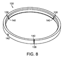
- 前記第2のロック部材は破断リングを備える、請求項1に記載の油圧カプラ。
- 前記破断リングは前記スリーブアセンブリの溝内に配置される、請求項7に記載の油圧カプラ。
- 前記少なくとも1つの第1のロック部材は、前記カプラ本体アセンブリの空洞内に少なくとも一部が配置され、前記少なくとも1つの第1のロック部材が前記ロック位置に移動する際に少なくとも一部が前記空洞から出て延在する、請求項1に記載の油圧カプラ。
- 前記少なくとも1つの第1のロック部材は複数の離間した第1のロック部材を備え、それぞれは前記カプラ本体アセンブリの空洞内に少なくとも一部が配置される、請求項9に記載の油圧カプラ。
- 前記第1のロック部材は概ね球形状を有する、請求項10に記載の油圧カプラ。
- 前記離間した第1のロック部材は、前記第1のロック部材が前記第2のロック部材の前記脆弱領域に直接接触しないように、前記第2のロック部材に位置合わせされる、請求項9に記載の油圧カプラ。
- 前記第2のロック部材の前記脆弱領域は隣接した第1のロック部材の間に等しい距離で位置付けられる、請求項12に記載の油圧カプラ。
- 前記第2のロック部材の前記脆弱領域の強度は、所定の負荷が前記少なくとも1つの第1のロック部材により前記第2のロック部材に加えられるとずれるように計算される、請求項1に記載の油圧カプラ。
- 前記第2のロック部材は、前記少なくとも1つの第1のロック部材から前記第2のロック部材の前記脆弱領域に力を均等に分散するように、前記少なくとも1つの第1のロック部材に対して位置合わせされる、請求項4に記載の油圧カプラ。
- 燃料ピットバルブ給油栓とともに流体経路を形成するために前記燃料ピットバルブ給油栓に取り外し可能に取り付け可能なカプラ本体アセンブリであって、前記カプラ本体アセンブリは、ロック位置と非ロック位置との間で移動可能な複数の離間した第1のロック部材を有し、前記ロック部材は前記カプラ本体アセンブリの離間した空洞内に少なくとも一部が配置され、空洞から少なくとも一部が延在し、前記第1のロック部材が前記ロック位置に移動すると前記燃料ピットバルブ給油栓と係合する、カプラ本体アセンブリと、
前記カプラ本体アセンブリに連結されたスリーブアセンブリと、
前記スリーブアセンブリの溝内に配置された破断リングから構成され、それに所定の負荷が加えられるとずれるように計算された脆弱領域を有する第2のロック部材であって、前記破断リングは、前記カプラ本体を前記給油栓に取り付けるロック位置に前記第1のロック部材を動かすために、前記第1のロック部材と選択的に移動可能に係合され、前記第1のロック部材を前記非ロック位置に動かすことができ、前記カプラ本体を前記給油栓から取り外すことができるために、前記第1のロック部材から係脱させるように選択的に移動可能である、第2のロック部材とを備え、
前記スリーブアセンブリは、前記破断リングを選択的に移動させて前記第1のロック部材に係合させ、また前記第1のロック部材から係脱させるために前記カプラ本体アセンブリに摺動可能に結合され、
前記油圧カプラの外部に所定量を超える負荷を加えると、前記少なくとも1つの第1のロック部材は前記破断リングに充分な力を加えることにより、前記破断リングの前記脆弱領域がずれ、前記第1のロック部材が前記ロック位置から前記非ロック位置に移動でき、前記油圧カプラを前記給油栓から取り外すことができる、分離油圧カプラ。 - 前記油圧カプラを通って流れる流体によってもたらされる圧力は前記破断リングに直接付与されない、または名目上最小に付与される、請求項16に記載の油圧カプラ。
- 前記破断リングは互いから概ね等しく離間された複数の脆弱領域を含む、請求項16に記載の油圧カプラ。
- 前記破断リングは、前記第1のロック部材から前記破断リングの前記脆弱領域に力を均等に分散するように、前記第1のロック部材に対して位置合わせされる、請求項18に記載の油圧カプラ。
- 前記破断リングの前記脆弱領域は、破断可能なリガメントを形成する低減された断面積を備える、請求項16に記載の油圧カプラ。
- 前記第1のロック部材は概ね球形状を有する、請求項16に記載の油圧カプラ。
- 前記第1のロック部材は、前記第1のロック部材が前記破断リングの前記脆弱領域に直接接触しないように、前記破断リングに位置合わせされる、請求項16に記載の油圧カプラ。
- 前記破断リングの前記脆弱領域は隣接した第1のロック部材の間に等しい距離で位置付けられる、請求項16に記載の油圧カプラ。
Applications Claiming Priority (5)
| Application Number | Priority Date | Filing Date | Title |
|---|---|---|---|
| US201462067899P | 2014-10-23 | 2014-10-23 | |
| US62/067,899 | 2014-10-23 | ||
| US14/856,227 US10697571B2 (en) | 2014-10-23 | 2015-09-16 | Breakaway hydraulic coupler |
| US14/856,227 | 2015-09-16 | ||
| PCT/US2015/050598 WO2016064496A1 (en) | 2014-10-23 | 2015-09-17 | Breakaway hydraulic coupler |
Publications (2)
| Publication Number | Publication Date |
|---|---|
| JP2017537277A true JP2017537277A (ja) | 2017-12-14 |
| JP6632617B2 JP6632617B2 (ja) | 2020-01-22 |
Family
ID=55761303
Family Applications (1)
| Application Number | Title | Priority Date | Filing Date |
|---|---|---|---|
| JP2017519560A Expired - Fee Related JP6632617B2 (ja) | 2014-10-23 | 2015-09-17 | 分離油圧カプラ |
Country Status (11)
| Country | Link |
|---|---|
| US (1) | US10697571B2 (ja) |
| EP (1) | EP3209914B1 (ja) |
| JP (1) | JP6632617B2 (ja) |
| KR (1) | KR102357771B1 (ja) |
| CN (1) | CN107110390B (ja) |
| AU (1) | AU2015337065B2 (ja) |
| CA (1) | CA2962743C (ja) |
| ES (1) | ES2766552T3 (ja) |
| IL (1) | IL251762B (ja) |
| RU (1) | RU2688088C2 (ja) |
| WO (1) | WO2016064496A1 (ja) |
Families Citing this family (5)
| Publication number | Priority date | Publication date | Assignee | Title |
|---|---|---|---|---|
| CN110966480B (zh) * | 2019-12-30 | 2021-08-17 | 武昌船舶重工集团有限公司 | 一种密封装置 |
| ES2960592T3 (es) | 2020-07-09 | 2024-03-05 | Vimasol E Hijos S L | Dispositivo para el suministro de combustible a aeronaves |
| US11603954B2 (en) * | 2020-08-28 | 2023-03-14 | Opw Fueling Components, Llc | Breakaway assembly |
| EP4432487A1 (en) | 2023-03-13 | 2024-09-18 | Universität Stuttgart | Radiation amplifying system |
| CN117030233B (zh) * | 2023-10-10 | 2023-12-08 | 安徽禄讯电子科技有限公司 | 一种耦合器拉力试验装置 |
Citations (7)
| Publication number | Priority date | Publication date | Assignee | Title |
|---|---|---|---|---|
| JPS4878428U (ja) * | 1971-12-25 | 1973-09-27 | ||
| JPS5192706U (ja) * | 1975-01-22 | 1976-07-24 | ||
| JPS5129547Y1 (ja) * | 1967-02-01 | 1976-07-26 | ||
| JPS52127626A (en) * | 1976-04-20 | 1977-10-26 | Tokico Ltd | Safty valve |
| JPS56144800U (ja) * | 1980-03-28 | 1981-10-31 | ||
| JPS60188689A (ja) * | 1984-03-09 | 1985-09-26 | 株式会社東京タツノ | 流体接手 |
| JPS6156300U (ja) * | 1984-09-19 | 1986-04-15 |
Family Cites Families (13)
| Publication number | Priority date | Publication date | Assignee | Title |
|---|---|---|---|---|
| US2836207A (en) * | 1955-06-13 | 1958-05-27 | Donald G Griswold | Aviation fueling hydrant valve |
| US3034544A (en) | 1957-01-11 | 1962-05-15 | Donald G Griswold | Hydrant valve |
| US3052488A (en) * | 1957-12-13 | 1962-09-04 | Earl F Bruning | Coupling with locking ball followers |
| US3317220A (en) * | 1963-04-15 | 1967-05-02 | Earl F Bruning | Releasable fluid coupling |
| US3398977A (en) * | 1965-02-13 | 1968-08-27 | Yoneda Rikizo | Pipe coupling |
| US4078577A (en) | 1973-03-26 | 1978-03-14 | International Telephone And Telegraph Corporation | Pressure control valve and coupling |
| US4348039A (en) | 1980-07-17 | 1982-09-07 | Big Inch Marine Systems, Inc. | Release coupling |
| US4691941A (en) | 1984-06-11 | 1987-09-08 | Charles Rabushka | Tension actuated uncoupler |
| US5145213A (en) * | 1990-11-30 | 1992-09-08 | Aeroquip Corporation | Frangible fitting assembly |
| JPH0753032Y2 (ja) * | 1991-06-11 | 1995-12-06 | 日東工器株式会社 | 管継手 |
| US6056010A (en) * | 1998-07-23 | 2000-05-02 | Aeroquip Corporation | Anti-check low spill fluid coupling |
| US6497120B1 (en) * | 2000-11-15 | 2002-12-24 | Joseph W. Kozora | Quick change connector for plunger for glass container forming process and equipment |
| US8006713B2 (en) | 2008-09-16 | 2011-08-30 | Eaton Corporation | Aviation fueling hydrant coupler with internal actuating collar lock |
-
2015
- 2015-09-16 US US14/856,227 patent/US10697571B2/en active Active
- 2015-09-17 RU RU2017109589A patent/RU2688088C2/ru active
- 2015-09-17 KR KR1020177014012A patent/KR102357771B1/ko not_active Expired - Fee Related
- 2015-09-17 AU AU2015337065A patent/AU2015337065B2/en not_active Ceased
- 2015-09-17 CN CN201580055243.8A patent/CN107110390B/zh not_active Expired - Fee Related
- 2015-09-17 CA CA2962743A patent/CA2962743C/en active Active
- 2015-09-17 EP EP15852813.3A patent/EP3209914B1/en active Active
- 2015-09-17 ES ES15852813T patent/ES2766552T3/es active Active
- 2015-09-17 WO PCT/US2015/050598 patent/WO2016064496A1/en not_active Ceased
- 2015-09-17 JP JP2017519560A patent/JP6632617B2/ja not_active Expired - Fee Related
-
2017
- 2017-04-18 IL IL251762A patent/IL251762B/en unknown
Patent Citations (7)
| Publication number | Priority date | Publication date | Assignee | Title |
|---|---|---|---|---|
| JPS5129547Y1 (ja) * | 1967-02-01 | 1976-07-26 | ||
| JPS4878428U (ja) * | 1971-12-25 | 1973-09-27 | ||
| JPS5192706U (ja) * | 1975-01-22 | 1976-07-24 | ||
| JPS52127626A (en) * | 1976-04-20 | 1977-10-26 | Tokico Ltd | Safty valve |
| JPS56144800U (ja) * | 1980-03-28 | 1981-10-31 | ||
| JPS60188689A (ja) * | 1984-03-09 | 1985-09-26 | 株式会社東京タツノ | 流体接手 |
| JPS6156300U (ja) * | 1984-09-19 | 1986-04-15 |
Also Published As
| Publication number | Publication date |
|---|---|
| KR102357771B1 (ko) | 2022-02-03 |
| CN107110390B (zh) | 2019-05-07 |
| AU2015337065A1 (en) | 2017-04-06 |
| RU2688088C2 (ru) | 2019-05-17 |
| KR20170072937A (ko) | 2017-06-27 |
| EP3209914A4 (en) | 2018-06-27 |
| AU2015337065B2 (en) | 2019-06-06 |
| US10697571B2 (en) | 2020-06-30 |
| CA2962743C (en) | 2021-05-25 |
| IL251762B (en) | 2021-07-29 |
| EP3209914A1 (en) | 2017-08-30 |
| CA2962743A1 (en) | 2016-04-28 |
| RU2017109589A3 (ja) | 2019-03-05 |
| IL251762A0 (en) | 2017-06-29 |
| JP6632617B2 (ja) | 2020-01-22 |
| US20160116094A1 (en) | 2016-04-28 |
| CN107110390A (zh) | 2017-08-29 |
| RU2017109589A (ru) | 2018-11-27 |
| ES2766552T3 (es) | 2020-06-12 |
| EP3209914B1 (en) | 2019-12-04 |
| WO2016064496A1 (en) | 2016-04-28 |
Similar Documents
| Publication | Publication Date | Title |
|---|---|---|
| JP6632617B2 (ja) | 分離油圧カプラ | |
| US9644443B1 (en) | Remotely-operated wellhead pressure control apparatus | |
| CN109642691B (zh) | 动力紧急释放联接器控制与监视系统 | |
| US8499842B2 (en) | Dual barrier plug system for a wellhead | |
| NO300146B1 (no) | Hydraulisk undervannskopling | |
| NO341261B1 (no) | Isolering av en rørledning | |
| NO20130705A1 (no) | Rørstreng med sperresystem | |
| CN107002894A (zh) | 可隔离的无撞击活塞式止回阀 | |
| EP3129694B1 (en) | Bi-directional hose break-away assembly | |
| US9845896B2 (en) | Shear valve | |
| EP2326863B1 (en) | Aviation fueling hydrant coupler with internal actuating collar lock | |
| US10597166B2 (en) | In-flight refueling probe for an aircraft | |
| CN111279110A (zh) | 改进的带减压装置的联接件 | |
| US20150047715A1 (en) | Valve assembly for use in a fuel dispensing system | |
| US7628172B2 (en) | Hose connection device | |
| RU2813001C1 (ru) | Муфта аварийного разъединения | |
| US9676495B2 (en) | Hydrant coupler with articulating handle assembly | |
| KR200487465Y1 (ko) | 하역암 스토퍼 핀 | |
| US20150226240A1 (en) | Fluid isolator | |
| Krywitsky et al. | An evaluation of technologies used for hazardous product transfer with regard to safety, environmental compliancy, and economic efficiency | |
| BR112019019013B1 (pt) | Método de conexão de um membro de conexão a um membro de perfil roscado | |
| HK1222224A1 (zh) | 用於燃料分配器的测试端口 |
Legal Events
| Date | Code | Title | Description |
|---|---|---|---|
| A621 | Written request for application examination |
Free format text: JAPANESE INTERMEDIATE CODE: A621 Effective date: 20180814 |
|
| A131 | Notification of reasons for refusal |
Free format text: JAPANESE INTERMEDIATE CODE: A131 Effective date: 20190716 |
|
| A977 | Report on retrieval |
Free format text: JAPANESE INTERMEDIATE CODE: A971007 Effective date: 20190712 |
|
| A521 | Request for written amendment filed |
Free format text: JAPANESE INTERMEDIATE CODE: A523 Effective date: 20190917 |
|
| TRDD | Decision of grant or rejection written | ||
| A01 | Written decision to grant a patent or to grant a registration (utility model) |
Free format text: JAPANESE INTERMEDIATE CODE: A01 Effective date: 20191126 |
|
| A61 | First payment of annual fees (during grant procedure) |
Free format text: JAPANESE INTERMEDIATE CODE: A61 Effective date: 20191210 |
|
| R150 | Certificate of patent or registration of utility model |
Ref document number: 6632617 Country of ref document: JP Free format text: JAPANESE INTERMEDIATE CODE: R150 |
|
| R250 | Receipt of annual fees |
Free format text: JAPANESE INTERMEDIATE CODE: R250 |
|
| LAPS | Cancellation because of no payment of annual fees |