JP2019085259A - Conveyance device, conveyance method, and actuator unit - Google Patents
Conveyance device, conveyance method, and actuator unit Download PDFInfo
- Publication number
- JP2019085259A JP2019085259A JP2017216829A JP2017216829A JP2019085259A JP 2019085259 A JP2019085259 A JP 2019085259A JP 2017216829 A JP2017216829 A JP 2017216829A JP 2017216829 A JP2017216829 A JP 2017216829A JP 2019085259 A JP2019085259 A JP 2019085259A
- Authority
- JP
- Japan
- Prior art keywords
- displacement
- actuator
- expansion
- transport
- contraction element
- Prior art date
- Legal status (The legal status is an assumption and is not a legal conclusion. Google has not performed a legal analysis and makes no representation as to the accuracy of the status listed.)
- Granted
Links
Images




Landscapes
- Jigging Conveyors (AREA)
- General Electrical Machinery Utilizing Piezoelectricity, Electrostriction Or Magnetostriction (AREA)
Abstract
【課題】振動搬送の技術を用いて物品を効率良く搬送することができる技術を提供する。【解決手段】所定の方向に伸縮変位する伸縮素子201の変位に対応する変位波形を出力するアクチュエータ200と、アクチュエータ200に、伸縮素子201の伸縮変位に対応する第1方向の変位と第1方向とは逆の第2方向の変位を繰り返す変位波形を生じさせ、アクチュエータ200が第1方向または第2方向に変位する際に、変位の変曲点が形成されるようにアクチュエータ200を動作させる駆動部300と、アクチュエータ200の変位が伝達され、その上を所定の物品が第1の方向または第2の方向に搬送される搬送レール400とを具備する。【選択図】図1PROBLEM TO BE SOLVED: To provide a technique capable of efficiently transporting an article by using a technique of vibration transport. SOLUTION: An actuator 200 that outputs a displacement waveform corresponding to a displacement of a telescopic element 201 that expands and contracts in a predetermined direction, and a displacement in a first direction and a first direction corresponding to the expansion and contraction displacement of the telescopic element 201 to the actuator 200. A drive that generates a displacement waveform that repeats displacement in the second direction opposite to that of the above, and operates the actuator 200 so that a displacement point is formed when the actuator 200 is displaced in the first direction or the second direction. A unit 300 and a transfer rail 400 on which the displacement of the actuator 200 is transmitted and a predetermined article is conveyed in the first direction or the second direction. [Selection diagram] Fig. 1
Description
本発明は、物品を搬送する搬送装置、搬送方法、およびそれに用いるアクチュエータユニットに関する。 BACKGROUND OF THE INVENTION Field of the Invention The present invention relates to a transfer device for transferring an article, a transfer method, and an actuator unit used therefor.
物品を搬送する搬送装置として、板ばね等で支持された搬送路を電磁石や圧電素子などのアクチュエータにより振動させることによって、搬送路上の物品を搬送するパーツフィーダが知られている。 As a conveying apparatus for conveying articles, there is known a parts feeder which conveys articles on a conveyance path by vibrating a conveyance path supported by a plate spring or the like by an actuator such as an electromagnet or a piezoelectric element.
パーツフィーダとして、特許文献1には、水平回転するボウルまたは水平に直線移動するフィーダを、カム機構を用い、往復に加速度差をつけて水平振動させることにより、摩擦力と慣性力を利用して被搬送体である物品(ワーク)を搬送するものが記載されている。 As a parts feeder, Patent Document 1 uses friction force and inertia force by horizontally oscillating a horizontally rotating bowl or a horizontally linearly moving feeder using a cam mechanism and oscillating horizontally with a reciprocating acceleration difference. What conveys the article (work) which is a to-be-conveyed body is described.
また、特許文献2には、両端が互いに平行な平面とされ、これら2つの平面に電極が形成されるとともに、その電極の形成された平面に平行に分極された圧電素子を設け、この圧電素子の一端を基板上に固定し、他端を被搬送体である物品と接する作用部として配設し、圧電素子の電極間に電圧を印加することにより作用部に、第1振動方向の速度と、この速度よりも小さな第2振動方向の速度とを発生させ、物品を第2振動方向へ送る搬送装置が記載されている。すなわち、速度が小さい第2振動方向の移動により、移動体は作用部とともに移動し、圧電素子が第1振動方向へ移動する際には速度が大きく、動摩擦係数は静摩擦係数よりも小さいため、物品は移動した後の位置からは動かず、圧電素子のみが第1振動方向に移動する。このため、この動作を繰り返すことにより、物品を第2振動方向に移動させることができる。
Further, in
上記特許文献1に記載された搬送装置では、相対滑りを生じさせて被搬送体である物品(ワーク)を効率良く搬送しようとしているが、滑りを生じさせ易くするためには、大きな駆動力により物品の摺動抵抗を軽減しなければならず、効率の良い搬送を行うことは困難である。また、搬送時の加速度が物品との静摩擦係数より大きくなると物品との間に滑りが発生して搬送効率が低下してしまう。 In the conveyance device described in the above-mentioned patent document 1, although relative slippage is caused to try to efficiently convey the article (workpiece) to be conveyed, in order to facilitate slippage, a large driving force is required. The sliding resistance of the article has to be reduced, and efficient transport is difficult. In addition, when the acceleration at the time of conveyance becomes larger than the coefficient of static friction with the article, slippage occurs with the article and the conveyance efficiency is lowered.
また、特許文献2の技術では、被搬送体である物品を搬送するためには、圧電素子を第2振動方向へゆっくりと伸長させた後、第1振動方向へ急速に縮退させるが、小型の物品を搬送する際には、圧電素子を第1振動方向へ急速に縮退しても、物品がそれに追従して第1振動方向に移動してしまう場合があり、また、圧電素子にこのような変位を高速で行わせると残留振動により効率の良い搬送は困難である。
Further, in the technique of
したがって、本発明は、振動搬送の技術を用いて被搬送体を効率良くかつ高速で搬送することができる技術を提供することを課題とする。 Therefore, an object of the present invention is to provide a technique capable of efficiently transporting a transported object at high speed using a technique of vibration transportation.
上記課題を解決するため、本発明は、以下の(1)〜(17)を提供する。 In order to solve the above-mentioned subject, the present invention provides the following (1)-(17).
(1)所定の方向に伸縮変位する伸縮素子の変位に対応する変位波形を出力するアクチュエータと、
前記アクチュエータに、前記伸縮素子の伸縮変位に対応する第1方向の変位と前記第1方向とは逆の第2方向の変位を繰り返す変位波形を生じさせ、前記アクチュエータが前記第1方向または前記第2方向に変位する際に、変位の変曲点が形成されるように前記アクチュエータを動作させる駆動部と、
前記アクチュエータの変位が伝達され、その上を被搬送体が前記第1の方向または前記第2の方向に搬送される搬送レールと
を具備することを特徴とする搬送装置。
(1) An actuator which outputs a displacement waveform corresponding to the displacement of the expansion / contraction element which is expanded / contracted in a predetermined direction,
The actuator generates a displacement waveform which repeats a displacement in a first direction corresponding to the expansion and contraction displacement of the expansion / contraction element and a displacement in a second direction opposite to the first direction, and the actuator generates the displacement waveform in the first direction or A driving unit that operates the actuator such that an inflection point of displacement is formed when displacing in two directions;
A transport apparatus comprising: a transport rail on which displacement of the actuator is transmitted, and on which the transported object is transported in the first direction or the second direction.
(2)前記駆動部は、前記アクチュエータが前記第1方向に変位している際に前記変曲点が形成されるように前記アクチュエータを動作させ、前記被搬送体は前記第1方向に搬送されることを特徴とする(1)に記載の搬送装置。 (2) The drive unit operates the actuator so that the inflection point is formed when the actuator is displaced in the first direction, and the transported object is transported in the first direction. The conveyance device according to (1), characterized in that
(3)前記駆動部は、前記アクチュエータが前記第2方向に変位している際に前記変曲点が形成されるように前記アクチュエータを動作させ、前記被搬送体は前記第2方向に搬送されることを特徴とする(1)に記載の搬送装置。 (3) The drive unit operates the actuator so that the inflection point is formed when the actuator is displaced in the second direction, and the transported object is transported in the second direction. The conveyance device according to (1), characterized in that
(4)前記アクチュエータは、前記伸縮素子の変位を前記搬送レールに伝達する変位伝達機構をさらに有することを特徴とする(1)から(3)のいずれかに記載の搬送装置。 (4) The conveyance device according to any one of (1) to (3), wherein the actuator further includes a displacement transmission mechanism that transmits the displacement of the expansion and contraction element to the conveyance rail.
(5)前記変位伝達機構は、前記伸縮素子の変位を拡大して出力し、前記搬送レールに伝達する変位拡大機構であることを特徴とする(4)に記載の搬送装置。 (5) The conveyance device according to (4), wherein the displacement transmission mechanism is a displacement enlargement mechanism that enlarges and outputs the displacement of the expansion and contraction element and transmits the displacement to the conveyance rail.
(6)前記アクチュエータは、前記第1方向および前記第2方向の変位を出力する変位出力部を有し、前記変位出力部に前記搬送レールの一方の端部が取り付けられ、前記変位出力部の変位が前記搬送レールに伝達されることを特徴とする(1)から(5)のいずれかに記載の搬送装置。 (6) The actuator has a displacement output unit for outputting displacements in the first direction and the second direction, one end of the transport rail is attached to the displacement output unit, and The transfer apparatus according to any one of (1) to (5), wherein the displacement is transmitted to the transfer rail.
(7)前記アクチュエータは、前記伸縮素子の変位を前記搬送レールに伝達する変位伝達機構をさらに有し、前記伸縮素子が水平方向に伸縮するように前記変位伝達機構に装着され、前記変位伝達機構は、前記伸縮素子の上方に設けられ、前記伸縮素子の伸縮変位と対応する方向に前記第1方向および前記第2方向の変位を出力する変位出力部材を有し、前記搬送レールは前記変位出力部材の上に取り付けられることを特徴とする(1)から(3)のいずれかに記載の搬送装置。 (7) The actuator further includes a displacement transmission mechanism for transmitting the displacement of the expansion and contraction element to the transport rail, and the expansion and contraction element is mounted on the displacement transmission mechanism so as to expand and contract in the horizontal direction. A displacement output member provided above the expansion and contraction element for outputting the displacement in the first direction and the second direction in a direction corresponding to the expansion and contraction displacement of the expansion and contraction element; The transport apparatus according to any one of (1) to (3), which is mounted on a member.
(8)搬送レール上で被搬送体を搬送する搬送方法であって、
所定の方向に伸縮変位する伸縮素子の変位に対応する変位波形を出力するアクチュエータに、前記伸縮素子の伸縮変位に対応する第1方向の変位と前記第1方向とは逆の第2方向の変位を繰り返す変位波形を生じさせ、前記アクチュエータが前記第1方向または前記第2方向に変位する際に、変位の変曲点が形成されるように前記アクチュエータを動作させ、
前記アクチュエータの変位を前記搬送レールに伝達させて、前記被搬送体を前記搬送レール上で前記第1方向または前記第2方向に搬送することを特徴とする搬送方法。
(8) A transport method for transporting a transported object on a transport rail, the transport method comprising:
The actuator for outputting a displacement waveform corresponding to the displacement of the expansion and contraction element displaced in a predetermined direction, the displacement in the first direction corresponding to the expansion and contraction displacement of the expansion and contraction element and the displacement in the second direction opposite to the first direction Generating a displacement waveform that is repeated, and operating the actuator such that an inflection point of displacement is formed when the actuator is displaced in the first direction or the second direction,
And transferring the displacement of the actuator to the transport rail to transport the transported object in the first direction or the second direction on the transport rail.
(9)前記アクチュエータが前記第1方向に変位している際に前記変曲点が形成されるように前記アクチュエータを動作させ、前記被搬送体は前記第1方向に搬送されることを特徴とする(8)に記載の搬送方法。 (9) The actuator is operated such that the inflection point is formed when the actuator is displaced in the first direction, and the transported object is transported in the first direction. The conveyance method as described in (8).
(10)前記アクチュエータが前記第2方向に変位している際に前記変曲点が形成されるように前記アクチュエータを動作させ、前記被搬送体は前記第2方向に搬送されることを特徴とする(8)に記載の搬送方法。 (10) The actuator is operated such that the inflection point is formed when the actuator is displaced in the second direction, and the transported object is transported in the second direction. The conveyance method as described in (8).
(11)搬送レール上で被搬送体を搬送するためのアクチュエータユニットであって、
所定の方向に伸縮変位する伸縮素子の変位に対応する変位波形を出力するアクチュエータと、
前記アクチュエータに、前記伸縮素子の伸縮変位に対応する第1方向の変位と前記第1方向とは逆の第2方向の変位を繰り返す変位波形を生じさせ、前記アクチュエータが前記第1方向または前記第2方向に変位する際に、変位の変曲点が形成されるように前記アクチュエータを動作させる駆動部と
を具備し、
前記搬送レールに前記アクチュエータの変位が伝達され、前記搬送レール上を前記被搬送体が前記第1の方向または前記第2の方向に搬送されることを特徴とするアクチュエータユニット。
(11) An actuator unit for transporting a transported object on a transport rail, the actuator unit comprising:
An actuator that outputs a displacement waveform corresponding to the displacement of the expansion / contraction element that is elastically displaced in a predetermined direction;
The actuator generates a displacement waveform which repeats a displacement in a first direction corresponding to the expansion and contraction displacement of the expansion / contraction element and a displacement in a second direction opposite to the first direction, and the actuator generates the displacement waveform in the first direction or And a drive unit for operating the actuator such that an inflection point of displacement is formed when displacing in two directions.
An actuator unit characterized in that the displacement of the actuator is transmitted to the transport rail, and the transported object is transported on the transport rail in the first direction or the second direction.
(12)前記駆動部は、前記アクチュエータが前記第1方向に変位している際に前記変曲点が形成されるように前記アクチュエータを動作させ、前記被搬送体は前記第1方向に搬送されることを特徴とする(11)に記載のアクチュエータユニット。 (12) The drive unit operates the actuator so that the inflection point is formed when the actuator is displaced in the first direction, and the transported object is transported in the first direction. The actuator unit according to (11), characterized in that
(13)前記駆動部は、前記アクチュエータが前記第2方向に変位している際に前記変曲点が形成されるように前記アクチュエータを動作させ、前記被搬送体は前記第2方向に搬送されることを特徴とする(11)に記載のアクチュエータユニット。 (13) The drive unit operates the actuator so that the inflection point is formed when the actuator is displaced in the second direction, and the transported object is transported in the second direction. The actuator unit according to (11), characterized in that
(14)前記アクチュエータは、前記伸縮素子の変位を前記搬送レールに伝達する変位伝達機構をさらに有することを特徴とする(11)から(13)のいずれかに記載のアクチュエータユニット。 (14) The actuator unit according to any one of (11) to (13), wherein the actuator further includes a displacement transmission mechanism that transmits the displacement of the telescopic element to the transport rail.
(15)前記変位伝達機構は、前記伸縮素子の変位を拡大して出力し、前記搬送レールに伝達する変位拡大機構であることを特徴とする(14)に記載のアクチュエータユニット。 (15) The actuator unit according to (14), wherein the displacement transmission mechanism is a displacement magnification mechanism that magnifies and outputs the displacement of the expansion and contraction element and transmits the displacement to the transport rail.
(16)前記アクチュエータは、前記第1方向および前記第2方向の変位を出力する変位出力部を有し、前記変位出力部に前記搬送レールの一方の端部が取り付けられ、前記変位出力部の変位が前記搬送レールに伝達されることを特徴とする(11)から(15)のいずれかに記載のアクチュエータユニット。 (16) The actuator has a displacement output unit that outputs displacement in the first direction and the second direction, one end of the transport rail is attached to the displacement output unit, and The actuator unit according to any one of (11) to (15), wherein a displacement is transmitted to the transport rail.
(17)前記アクチュエータは、前記伸縮素子の変位を前記搬送レールに伝達する変位伝達機構をさらに有し、前記伸縮素子が水平方向に伸縮するように前記変位伝達機構に装着され、前記変位伝達機構は、前記伸縮素子の上方に設けられ、前記伸縮素子の伸縮変位と対応する方向に前記第1方向および前記第2方向の変位を出力する変位出力部材を有し、前記搬送レールは前記変位出力部材の上に取り付けられることを特徴とする(11)から(13)のいずれかに記載のアクチュエータユニット。 (17) The actuator further includes a displacement transmission mechanism for transmitting the displacement of the expansion and contraction element to the transport rail, and the expansion and contraction element is mounted on the displacement transmission mechanism so as to expand and contract in the horizontal direction. A displacement output member provided above the expansion and contraction element for outputting the displacement in the first direction and the second direction in a direction corresponding to the expansion and contraction displacement of the expansion and contraction element; The actuator unit according to any one of (11) to (13), which is mounted on a member.
本発明によれば、振動搬送の技術を用いて少ない消費電力で効率良く、被搬送体の搬送量を稼ぐことができ、かつ高速搬送を実現することができる。 According to the present invention, it is possible to earn the amount of conveyance of the object to be conveyed efficiently and with low power consumption by using the technique of vibration conveyance, and to realize high-speed conveyance.
以下、本発明の実施の形態について詳細に説明する。
<第1の実施形態>
最初に本発明の第1の実施形態について説明する。
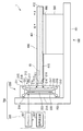
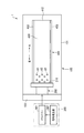
図1は本発明の第1の実施形態に係る搬送装置を示す側面図、図2はその平面図である。
これらの図に示すように、本実施形態の搬送装置1は、水平部101および垂直部102を有するベース部材100と、ベース部材100の垂直部102に固定され所定波形の変位を出力するアクチュエータ200と、アクチュエータ200を駆動する駆動部300と、アクチュエータ200の変位が伝達され、物品10を搬送する搬送レール400と、ベース部材100の水平部101に取り付けられ、搬送レール400を移動可能に支持する支持部500と、支持部500と搬送レール400の間に設けられたリニアガイド600とを有する。アクチュエータ200と駆動部300とによりアクチュエータユニット700を構成する。
Hereinafter, embodiments of the present invention will be described in detail.
First Embodiment
First, the first embodiment of the present invention will be described.
FIG. 1 is a side view showing a transport apparatus according to a first embodiment of the present invention, and FIG. 2 is a plan view thereof.
As shown in these figures, the transport apparatus 1 of the present embodiment includes a
アクチュエータ200は、電圧等のトリガーを与えることにより伸縮する伸縮素子201と、この伸縮素子201が装着され、伸縮素子201の変位を搬送レール400に伝達する変位伝達機構としての変位拡大機構210とを具備している。
The
伸縮素子201は、長尺状をなし、長手方向を鉛直にして配置されている。伸縮素子201としては、トリガーが与えられることにより主に長手方向に伸縮する素子であればよく、電圧に応じて変位する圧電素子、磁界に応じて変位する磁歪素子、温度に応じて変位する形状記憶合金素子等を挙げることができる。いずれの素子の場合にも電源からの電圧を直接印加するか、または電圧を適宜の手段で磁界や温度に変換して用いることにより電圧に応じた変位を実現することができる。 The expansion and contraction element 201 has a long shape and is disposed with its longitudinal direction vertical. The expansion / contraction element 201 may be any element that can be expanded / contracted mainly in the longitudinal direction by the application of a trigger, a piezoelectric element displaced according to voltage, a magnetostrictive element displaced according to a magnetic field, a shape displaced according to temperature A memory alloy element etc. can be mentioned. In any of the elements, displacement according to the voltage can be realized by directly applying a voltage from a power supply or converting the voltage into a magnetic field or temperature by an appropriate means.
伸縮素子201としては、圧電素子が好ましい。圧電素子を用いたアクチュエータは、(1)投入される電気エネルギーに対して実に60%以上が機械エネルギーに変換され、例えば10mm×10mmの素子で発生する力が300kgfに達し、エネルギー効率が極めて高い、(2)数kHz以上の高速応答が可能である、(3)物体を一定の位置で保持する場合に、電圧を印加する必要はあるが、電流は流れなくて済むため、電気エネルギー消費を抑えることができる、(4)小型化、薄型化に適している、等の優れた点を有している。 As the expansion and contraction element 201, a piezoelectric element is preferable. In an actuator using a piezoelectric element, (1) 60% or more of the input electric energy is actually converted to mechanical energy, and a force generated by, for example, a 10 mm × 10 mm element reaches 300 kgf, and the energy efficiency is extremely high (2) A high speed response of several kHz or more is possible. (3) When an object is held at a fixed position, although it is necessary to apply a voltage, no current flows, so electrical energy consumption is reduced. (4) suitable for downsizing and thinning, and the like.
伸縮素子201として用いられる圧電素子としては、板状の圧電体が電極を挟んで複数積層されて構成された積層タイプのものが用いられる。例えば、10mm×10mmの圧電体を40mm程度の長さに積層して直方体として構成される。圧電体を構成する圧電材料としては、圧電効果を有するセラミック材料が用いられ、そのような材料として、典型的にはチタン酸ジルコン酸鉛(Pb(Zr,Ti)O3;PZT)を挙げることができる。伸縮素子201の形状は直方体に限らず、例えば三角柱や六角柱等の多角柱であっても、円柱であってもよい。 As a piezoelectric element used as the expansion and contraction element 201, a laminated type in which a plurality of plate-like piezoelectric members are stacked with an electrode interposed therebetween is used. For example, a 10 mm × 10 mm piezoelectric body is stacked in a length of about 40 mm to form a rectangular parallelepiped. As a piezoelectric material constituting the piezoelectric body, a ceramic material having a piezoelectric effect is used. As such a material, typically, lead zirconate titanate (Pb (Zr, Ti) O 3 ; PZT) is mentioned Can. The shape of the expansion and contraction element 201 is not limited to a rectangular parallelepiped, and may be, for example, a polygonal prism such as a triangular prism or a hexagonal prism, or a cylinder.
変位拡大機構210は、伸縮素子201の変位を拡大して出力し、その拡大された変位を搬送レール400に伝達するものであり、本例では、長尺体からなる伸縮素子201の一端面および他端面にそれぞれ固定された第1の取り付け部材211および第2の取り付け部材212と、伸縮素子201の一方の側面に、これら第1の取り付け部材211および第2の取り付け部材212を連結するように設けられ、圧電素子の変位方向に直交する方向に拡大された変位を出力する変位伝達部213と、伸縮素子201の他方の側面に、第1の取り付け部材211および第2の取り付け部材212を、可撓性を有するヒンジ216を介して連結するように設けられた固定部材214とを有する。変位伝達部213は、中央に出力部材215を有し、複数の可撓性を有するヒンジ216および複数のアーム217の作用により出力部材215から拡大された変位を出力することが可能となっている。出力部材215には搬送レール400が取り付けられる取り付け部材218が装着されている。固定部材214の表面は固定面であり、ベース部材100の垂直部102に固定される。
The
このような構成の変位拡大機構210に伸縮素子201が装着されることによりアクチュエータ200が構成される。なお、変位拡大機構は、図示したような構成に限らず種々の構成をとることができる。また、変位伝達機構としては、変位を拡大せずに伸縮素子201の変位を伝達する機能のみを有するものであってもよい。また、変位伝達機構を用いずに、伸縮素子のみでアクチュエータ200を構成してもよい。
The
伸縮素子201が圧電素子の場合、脆性材料であるセラミックス材料で構成されており、引張り力に対して弱い。このため、図示するように、伸縮素子201に与圧機構220により長手方向に圧縮力を与えられた状態で変位拡大機構210に装着されることが好ましい。与圧機構220により予め圧縮力を与えることによりこのような欠点を軽減することができる。与圧機構220は、本例では、伸縮素子201の一端面および他端面に固定される一対のヘッドピース221,222と、これらの間に架け渡されるように設けられた例えば2本の圧縮力付与部材223とを有している。ただし、与圧機構の構成は、圧縮力を付与できればこれに限るものではない。なお、与圧機構220は設けなくともよく、また、変位拡大機構(変位伝達機構)に与圧機構としての機能を持たせてもよい。
When the expansion and contraction element 201 is a piezoelectric element, it is made of a ceramic material which is a brittle material and is weak against a tensile force. For this reason, as shown in the drawing, it is preferable that the elastic element 201 be attached to the
駆動部300は、伸縮素子201を伸縮駆動させるドライバー301と、所定波形の信号を発生してドライバー301に供給する信号発生部302を有している。ドライバー301は、電源と駆動回路とを有している。伸縮素子201が圧電素子である場合には、ドライバー301は、圧電素子である伸縮素子201に信号発生部302から所定の波形の信号に応じて所定の電圧を印加して充放電させることにより伸縮素子201を駆動する。
The
駆動部300により伸縮素子201が所定の波形で伸縮駆動され、変位拡大機構210の出力部材215から、その伸縮駆動の波形に対応した変位波形が出力される。このときの出力される変位波形については後述する。
The expansion and contraction element 201 is driven to expand and contract with a predetermined waveform by the
搬送レール400は、変位拡大機構210の出力部材215に装着された取り付け部材218に着脱可能に取り付けられており、出力部材215から出力される変位波形が直接伝達される。搬送レール400は、複数の物品10が載せられる搬送面401と、搬送面401から物品10が落下しないように搬送面401の両側部に設けられたガード部材403を有している。また、搬送レール400は、アクチュエータ側の第1の端部411と、先端側の第2の端部412とを有しており、これらの間で物品10が搬送される。このとき、後述するように、アクチュエータ200から出力される変位波形を、変曲点を有するものとし、その変曲点を形成する位置を調整することにより、物品10を第1の端部411から第2の端部412に搬送することも、第2の端部412から第1の端部411に搬送することもできる。物品10は特に限定されず、ボルトやナット等の部品でもよいし、重量が大きいものであってもよいが、特に、直径0.5mm以下の小さいものに対して有効である。
The
搬送レール400の下部には、長手方向に沿ってガイドレール410が設けられている。そして、このガイドレール410にリニアガイド600が装着され、搬送レール400は、ベース部材100の水平部101に取り付けられた支持部500にリニアガイド600を介して支持されている。このため、搬送レール400は、アクチュエータ200の変位に追従して移動することができる。
At the lower part of the
このように構成される搬送装置1においては、駆動部300の信号発生部302からの信号に基づいて、ドライバー301から伸縮素子201に所定波形の電圧が印加され、伸縮素子201は伸縮変位を高速で繰り返す。この伸縮変位は、変位伝達機構である変位拡大機構210により拡大された変位として出力部材215から出力され、この変位が搬送レール400に伝達される。
In the transport apparatus 1 configured as described above, a voltage of a predetermined waveform is applied from the
出力部材215は、伸縮素子201の伸縮変位に対応して、基本的に、電圧非印加時の基準位置から水平方向へ進出する第1方向であるA方向の変位と、進出した位置から基準位置に戻る第2方向であるB方向の変位とを高速で繰り返す変位波形により変位し、これにともなって搬送レール400も同様に変位する。このとき、アクチュエータ200(出力部材215)に基づく搬送レール400の変位波形において、A方向およびB方向のうち、物品10を搬送しようとする方向に変位している際に、変位の変曲点が生じるように、伸縮素子201を駆動する。ここで変位の変曲点とは、速度が極値(極大値または極小値)になる点をいう。
The output member 215 basically corresponds to the displacement in the A direction, which is the first direction advancing horizontally from the reference position when no voltage is applied, and the reference position from the advanced position, corresponding to the expansion and contraction displacement of the expansion and contraction element 201 The displacement in the direction B, which is the second direction back to the above, is repeated at a high speed, so that the
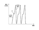
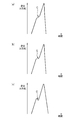
具体的には、物品10を第1方向であるA方向に搬送しようとする際には、アクチュエータ200から出力される変位波形の一例としては、図3に示すようなものとなる。すなわち、アクチュエータ200がA方向に変位しているときに、その途中に変曲点Cが形成されるように、伸縮素子201を駆動する。
Specifically, when the
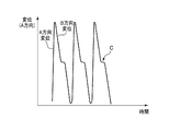
逆に、物品10を第2方向であるB方向に搬送しようとする際には、アクチュエータ200から出力される変位波形の一例としては、図4に示すようなものとなる。すなわち、アクチュエータ200がB方向に変位しているときに、その途中に変曲点Cが形成されるように、伸縮素子201を駆動する。
Conversely, when the
変位の変曲点としては、図5のように、A方向に一定の速度で変位している途中で、(a)に示すようにA方向の変位を保ったまま変位の速度が低下する場合、(b)に示すように変位変化が0になる場合、(c)に示すように変位がB方向に逆転する場合のいずれであってもよい。変曲点で速度または加速度が変化した後は、所定期間で変位の速度が元の速度に戻る。 As the inflection point of displacement, as shown in FIG. 5, in the middle of displacement at a constant speed in the A direction, as shown in (a), when the displacement speed decreases while maintaining the displacement in the A direction When the displacement change is zero as shown in (b), the displacement may be reversed in the B direction as shown in (c). After the velocity or acceleration changes at the inflection point, the velocity of displacement returns to the original velocity for a predetermined period.
このような変曲点を有するアクチュエータ200の変位すなわち搬送レール400の変位を実現するためには、対応する電圧波形をコンピュータで合成してもよいし、信号発生装置で発生した2つ以上の波形を合成してもよいし、プレパルスを利用してもよい。
In order to realize the displacement of the
次に、本発明における物品搬送の原理について説明する。
アクチュエータ200により搬送レール400を一方向に変位させると、搬送面401上の物品10は、静止摩擦により搬送レール400の移動方向に加速力が伝達される。加速力を得た物品10は搬送面401との間に滑りが生じた状態となり、搬送レール400よりも低速で搬送レールの変位方向に移動する。そしてアクチュエータ200により搬送レール400が搬送方向に変位している途中で変位の変曲点Cを設けることにより、搬送レール400の速度が変化し、ある時点で搬送レール400と物品10との相対速度差が0となる。この相対速度差が0になる時点において、搬送レール400と物品10との間に再び静止摩擦が生じる。その後、搬送レール400は加速され、その際に静止摩擦により搬送レール400から物品10に加速力が伝達されて、その結果、物品10が加速され、搬送レール400の変位が逆向きになった際にも、物品10は摩擦力に抗して搬送面401上を搬送方向に向けて変位する。このため、伸縮素子201が伸長して戻るまでの変位に対応する搬送レール400の一回の変位波形で、物品10を大きく変位させることができ、搬送レール400にこのような変位波形を繰り返し与えることにより、物品10を効率良く搬送することができる。また搬送レールを駆動する周波数を高くすることができるので、高速搬送が可能である。このように、1回目の加速力により搬送レール400上で物品10を滑らせながら、搬送レール400の変位に変曲点Cを設けて、物品10に2回目の加速力を加えるため、一回の変位波形で物品10に2回の加速力を加えることができ、少ない消費電力で効率良く、物品の搬送量を稼ぐことができ、かつ高速搬送が実現できる。
Next, the principle of article transport in the present invention will be described.
When the
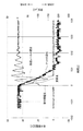
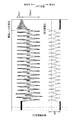
図6は、このことを示す実験結果である。ここでは、物品として直径約10mmのナットを用いた。図6では、横軸に時間をとり、縦軸に端子間電圧および変位をとっている。搬送レールおよびナットの変位は、搬送レール400の先端側に設けられたレーザー距離計により測定した。なお、図6は、搬送レール400にA方向およびB方向の変位を一往復与えた場合を示し、変位の方向は、図3、図4とは逆で、正方向(上方向)がB方向(戻り方向)であり、負方向(下方向)がA方向(伸長方向)である。
FIG. 6 is an experimental result showing this. Here, a nut with a diameter of about 10 mm was used as an article. In FIG. 6, time is taken on the horizontal axis, and terminal voltage and displacement are taken on the vertical axis. The displacement of the transport rail and the nut was measured by a laser range finder provided on the front end side of the
図6に示すように、搬送レール400を搬送方向であるA方向に変位させている途中で、変位の変曲点を形成することで、搬送レール400の変位方向がB方向に転じた後もナットがA方向へ変位していることがわかる。このことから、物品であるナットを効率良く搬送できること、つまり、一回の変位波形で物品10に2回の加速力を加えて、少ない消費電力で効率良く物品の搬送量を稼ぐことができ、かつ高速搬送が実現できることが確認された。
As shown in FIG. 6, by forming the inflection point of the displacement while displacing the
また、本実施形態では、アクチュエータ200および搬送レール400の変位波形における変曲点の位置により物品10をA方向にもB方向にも搬送することができるという利点も得られる。
Further, in the present embodiment, the position of the inflection point in the displacement waveform of the
さらに、伸縮素子、特に圧電素子は、0.1〜50μm程度の小さな変位で駆動することができるので、直径0.5mm以下の小さな物品であっても、部品の搬送先との間の継ぎ目を物品の落下の危険性が生じない程度に狭くすることができ、しかも、変曲点を設けることにより、残留振動が低減され、残留振動の影響をほとんど受けずに高速駆動が可能であるため、1回の変位が小さくても十分に高い搬送速度で物品を搬送することができる。 Furthermore, since the expansion and contraction element, particularly the piezoelectric element, can be driven with a small displacement of about 0.1 to 50 μm, even a small article having a diameter of 0.5 mm or less, the joint between the part and the transfer destination It can be narrowed to the extent that the risk of falling of the article does not occur, and furthermore, by providing the inflection point, the residual vibration is reduced, and high speed driving is possible with almost no influence of the residual vibration, The article can be transported at a sufficiently high transport speed even if the displacement per one time is small.
次に、実際に変曲点を有する変位波形を搬送レールに繰り返し与えて搬送実験を行った結果について説明する。 Next, a result of carrying out a carrying out experiment by giving a displacement waveform having an inflection point actually to a carrying rail repeatedly will be described.
ここでは、伸縮素子として圧電素子を用いたアクチュエータにより、搬送レール上の物品として直径約10mmのナットを搬送する実験を行った。端子間電圧を150Vとし、圧電素子を伸長して元に戻すまでの1波長の時間を8msecとし、最大変位を150μmとし、電圧波形を変化させて、種々の変曲点を有する変位波形を形成して搬送レールを振動させてナットの搬送実験を行った。 Here, an experiment was conducted in which a nut having a diameter of about 10 mm was conveyed as an article on a conveyance rail by an actuator using a piezoelectric element as an expansion and contraction element. The voltage between the terminals is 150 V, the time for one wavelength until the piezoelectric element is extended and restored is 8 msec, the maximum displacement is 150 μm, the voltage waveform is changed, and displacement waveforms having various inflection points are formed. Then, the conveyance rail was vibrated to conduct a nut conveyance experiment.
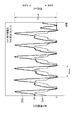
図7〜9は、搬送レールが圧電素子の伸長方向に対応するA方向に変位する際に変曲点が形成される変位波形とその変位波形を形成した際の電圧波形の例を示す図であり、図10〜11は、搬送レールが圧電素子の戻り方向に対応するB方向に変位する際に変曲点が形成される変位波形とその変位波形を形成した際の電圧波形の例を示す図である。なお、これらの図においては、変位の方向は、図3、図4と同様、正方向(上方向)がA方向(伸長方向)であり、負方向(下方向)がB方向(戻り方向)である。 7 to 9 are diagrams showing an example of a displacement waveform in which an inflection point is formed when the transport rail is displaced in the A direction corresponding to the extension direction of the piezoelectric element and a voltage waveform when the displacement waveform is formed. 10 to 11 show an example of a displacement waveform in which an inflection point is formed when the transport rail is displaced in the B direction corresponding to the return direction of the piezoelectric element, and a voltage waveform when the displacement waveform is formed. FIG. In these figures, the direction of displacement is the same as in FIGS. 3 and 4 in the positive direction (upward direction) being the A direction (stretching direction) and the negative direction (downward direction) being the B direction (returning direction) It is.
図7〜9の場合は、いずれもナットをA方向に搬送することができ、その際の平均搬送速度は、12〜20mm/secであった。また、図10〜11の場合は、いずれもナットをB方向に搬送することができ、その際の平均速度は、8〜10mm/secであった。このように、本発明により効率良くかつ高速な搬送が可能なことが確認された。 In the cases of FIGS. 7 to 9, the nuts can be transported in the A direction, and the average transport speed at that time is 12 to 20 mm / sec. Moreover, in the case of FIGS. 10-11, all could convey a nut in B direction, and the average speed in that case was 8-10 mm / sec. Thus, it has been confirmed that the present invention enables efficient and high-speed transport.
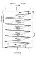
図12は、搬送レールが圧電素子の戻り方向に対応するB方向に変位する際に変曲点を設けた場合のナットの変位と搬送レールの変位波形の一例を示す図であり、図13は、その際の端子間電圧と搬送レールの変位を拡大して示す図である。なお、図12、13においては、変位の方向は、図7〜11とは逆で、正方向(上方向)がB方向(戻り方向)であり、負方向(下方向)がA方向(伸長方向)である。この場合、図12に示すように、ナットは最初の15波形までは、逆方向のA方向に搬送され、それ以降B方向に搬送される現象がみられた。これは、最初の圧電素子の伸長に対応する搬送レールのA方向の変位によりナットがA方向に搬送される影響が残留したためと考えられる。この現象の時間はわずかであるから、B方向の搬送には大きな影響はおよぼさない。 FIG. 12 is a view showing an example of the displacement of the nut and the displacement waveform of the transport rail when the inflection point is provided when the transport rail is displaced in the B direction corresponding to the return direction of the piezoelectric element. It is a figure which expands and shows the voltage between terminals in that case, and the displacement of a conveyance rail. In FIGS. 12 and 13, the displacement direction is opposite to that in FIGS. 7 to 11, and the positive direction (upward) is the B direction (return direction) and the negative direction (downward) is the A direction (stretching) Direction). In this case, as shown in FIG. 12, a phenomenon was observed in which the nut was transported in the reverse direction A direction up to the first 15 waveforms and thereafter transported in the B direction. This is considered to be due to the fact that the nut is transported in the A direction by the displacement of the transport rail in the A direction corresponding to the extension of the first piezoelectric element. Since the time of this phenomenon is short, the transport in the B direction is not greatly affected.
<第2の実施形態>
次に本発明の第1の実施形態について説明する。
図14は本発明の第2の実施形態に係る搬送装置を示す側面図である。
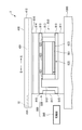
この図に示すように、本実施形態の搬送装置2は、所定波形の変位を出力するアクチュエータ800と、アクチュエータ800を駆動する駆動部300と、アクチュエータ800の変位が伝達され、物品10を搬送する搬送レール400とを有する。アクチュエータ800と駆動部300とでアクチュエータユニット900を構成する。アクチュエータ800は、基台1000上に載置または固定される。
Second Embodiment
Next, a first embodiment of the present invention will be described.
FIG. 14 is a side view showing a transfer apparatus according to a second embodiment of the present invention.
As shown in this figure, the
アクチュエータ800は、電圧等のトリガーを与えることにより伸縮する伸縮素子801と、この伸縮素子801が装着され、伸縮素子801の変位を搬送レール400に伝達する変位伝達機構810とを具備している。
The
伸縮素子801は、長尺状をなし、長手方向を水平にして配置されている。伸縮素子801としては、伸縮素子201と同様、トリガーが与えられることにより主に長手方向に伸縮する素子であればよく、電圧に応じて変位する圧電素子、磁界に応じて変位する磁歪素子、温度に応じて変位する形状記憶合金素子等を挙げることができ、これらの中では圧電素子が好ましい。
The expansion and
変位伝達機構810は、伸縮素子801の変位を搬送レール400に伝達するものであり、基台1000に載置または固定されるベース部材811と、ベース部材811と一体またはベース部材811に固定して設けられ、伸縮素子801の一端が取り付けられる第1の取り付け部材812と、伸縮素子801の他端が移動可能に取り付けられる第2の取り付け部材813と、伸縮素子801の上方に水平に設けられ、伸縮素子801の伸縮変位に対応した水平方向の所定波形の変位を出力する出力部材814とを有している。第2の取り付け部材813は、ベース部材811の一端および出力部材814の対応する一端に、それぞれ可撓性を有するヒンジ815を介して連結されている。一方、ベース部材811の他端および出力部材814の対応する他端には、中間部材816がそれぞれ可撓性を有するヒンジ815を介して連結されている。出力部材814の上には搬送レール400が取り付けられる取り付け部材816が装着され、搬送レール400は、取り付け部材816を介して出力部材814上に取り付けられている。
The
このような構成の変位伝達機構810に伸縮素子801が装着されることによりアクチュエータ800が構成される。
The
伸縮素子801には、その長手方向に予め圧縮力を与える与圧機構820が装着されている。与圧機構820は、上述した与圧機構220と同様の機能を有しており、本例では、伸縮素子801の一端面および他端面に固定される一対のヘッドピース821,822と、これらの間に架け渡されるように設けられた例えば2本の圧縮力付与部材823とを有している。ただし、与圧機構の構成は、圧縮力を付与できればこれに限るものではない。なお、与圧機構820は設けなくともよく、また、変位伝達機構に与圧機構としての機能を持たせてもよい。
A
駆動部300は、第1の実施形態と同様、ドライバーと、所定波形の信号を発生してドライバーに供給する信号発生部とを有している。詳細については第1の実施形態と同様であるから省略する。駆動部300により伸縮素子801が所定の波形で伸縮駆動され、変位伝達機構810の出力部材814から、その伸縮駆動の波形に対応した変位波形が出力される。このときの出力される変位波形は第1の実施形態と同様である。
As in the first embodiment, the
搬送レール400は、第1の実施例と同様に構成され、変位伝達機構810の出力部材814に装着された取り付け部材816に着脱可能に取り付けられており、出力部材814から出力される変位波形が直接伝達される。第1の実施形態と同様、物品10は特に限定されず、ボルトやナット等の部品でもよいし、重量が大きいものであってもよいが、特に、直径0.5mm以下の小さいものに対して有効である。
The
出力部材814は、伸縮素子801の伸縮変位に対応して、基本的に、電圧非印加時の基準位置から伸縮素子801が伸長する第1方向であるA方向の変位と、伸長した位置から基準位置に戻る第2方向であるB方向の変位とを高速で繰り返す変位波形により変位し、これにともなって搬送レール400も同様に変位する。このとき、第1の実施形態と同様、アクチュエータ800(出力部材814)に基づく搬送レール400の変位波形において、A方向およびB方向のうち、物品10を搬送しようとする方向に変位している際に、変位の変曲点が生じるように、伸縮素子801を駆動する。
The
これにより、第1の実施形態と同様の原理で、伸縮素子801が伸長して戻るまでの変位に対応する搬送レール400の一回の変位波形で、物品10を大きく変位させることができ、搬送レール400にこのような変位波形を繰り返し与えることにより、物品10を効率良く搬送することができる。
Thereby, the
また、本実施形態においても、アクチュエータ800および搬送レール400の変位波形における変曲点の位置により物品10をA方向にもB方向にも搬送することができるという利点も得られる。
Also in this embodiment, the position of the inflection point in the displacement waveform of the
さらに、伸縮素子、特に圧電素子は、0.1〜50μm程度の小さな変位で駆動することができるので、直径0.5mm以下の小さな物品であっても、部品の搬送先との間の継ぎ目を物品の落下の危険性が生じない程度に狭くすることができ、しかも、変曲点を設けることにより、残留振動が低減され、残留振動の影響をほとんど受けずに高速駆動が可能であるため、1回の変位が小さくても十分に高い搬送速度で物品を搬送することができる。 Furthermore, since the expansion and contraction element, particularly the piezoelectric element, can be driven with a small displacement of about 0.1 to 50 μm, even a small article having a diameter of 0.5 mm or less, the joint between the part and the transfer destination It can be narrowed to the extent that the risk of falling of the article does not occur, and furthermore, by providing the inflection point, the residual vibration is reduced, and high speed driving is possible with almost no influence of the residual vibration, The article can be transported at a sufficiently high transport speed even if the displacement per one time is small.
さらにまた、本実施形態では搬送レール400の第1の端部411および第2の端部412のいずれも開放されているので、これらのいずれにも物品10の搬送先の部材を設けることが可能であるという利点を得ることができる。
Furthermore, in the present embodiment, since both the
以上、本発明の実施の形態について説明したが、本発明は上記実施形態に限定されることなく、種々変形可能である。例えば、上記実施形態では圧電素子を与圧機構により予め圧縮力を与えた例を示したが、与圧機構は必須ではない。また、変位伝達機構は、上記実施形態に限定されるものではなく、上述した変曲点を有する所望の変位波形を形成し、搬送レールに伝達することができるものであればよく、さらに、上述した変曲点を有する所望の変位波形を実現することができれば変位伝達機構を設けなくてもよい。 As mentioned above, although embodiment of this invention was described, this invention can be variously deformed, without being limited to the said embodiment. For example, although the example which gave compressive force beforehand by the pressurization mechanism was shown in the said embodiment, the pressurization mechanism is not essential. Further, the displacement transfer mechanism is not limited to the above embodiment, and it may be any mechanism capable of forming a desired displacement waveform having the inflection point described above and transmitting it to the transport rail, and further, as described above If a desired displacement waveform having the inflection point can be realized, the displacement transmission mechanism may not be provided.
さらにまた、アクチュエータユニットの構成は、搬送レールに物品の搬送が可能な上記変位波形を伝達できるものであれば、上記2つの実施形態に限定されるものではない。 Furthermore, the configuration of the actuator unit is not limited to the above two embodiments as long as it can transmit the displacement waveform capable of transporting the article to the transport rail.
1,2;搬送装置
10;物品(被搬送体)
100;ベース部材
200,800;アクチュエータ
201,801;伸縮素子
210;変位拡大機構(変位伝達機構)
300;駆動部
400;搬送レール
500;支持部
600;リニアガイド
700,900;アクチュエータユニット
1000;基台
1, 2; conveying
100;
300; drive
Claims (17)
前記アクチュエータに、前記伸縮素子の伸縮変位に対応する第1方向の変位と前記第1方向とは逆の第2方向の変位を繰り返す変位波形を生じさせ、前記アクチュエータが前記第1方向または前記第2方向に変位する際に、変位の変曲点が形成されるように前記アクチュエータを動作させる駆動部と、
前記アクチュエータの変位が伝達され、その上を被搬送体が前記第1の方向または前記第2の方向に搬送される搬送レールと
を具備することを特徴とする搬送装置。 An actuator that outputs a displacement waveform corresponding to the displacement of the expansion / contraction element that is elastically displaced in a predetermined direction;
The actuator generates a displacement waveform which repeats a displacement in a first direction corresponding to the expansion and contraction displacement of the expansion / contraction element and a displacement in a second direction opposite to the first direction, and the actuator generates the displacement waveform in the first direction or A driving unit that operates the actuator such that an inflection point of displacement is formed when displacing in two directions;
A transport apparatus comprising: a transport rail on which displacement of the actuator is transmitted, and on which the transported object is transported in the first direction or the second direction.
所定の方向に伸縮変位する伸縮素子の変位に対応する変位波形を出力するアクチュエータに、前記伸縮素子の伸縮変位に対応する第1方向の変位と前記第1方向とは逆の第2方向の変位を繰り返す変位波形を生じさせ、前記アクチュエータが前記第1方向または前記第2方向に変位する際に、変位の変曲点が形成されるように前記アクチュエータを動作させ、
前記アクチュエータの変位を前記搬送レールに伝達させて、前記被搬送体を前記搬送レール上で前記第1方向または前記第2方向に搬送することを特徴とする搬送方法。 A transport method for transporting a transported object on a transport rail, the transport method comprising:
The actuator for outputting a displacement waveform corresponding to the displacement of the expansion and contraction element displaced in a predetermined direction, the displacement in the first direction corresponding to the expansion and contraction displacement of the expansion and contraction element and the displacement in the second direction opposite to the first direction Generating a displacement waveform that is repeated, and operating the actuator such that an inflection point of displacement is formed when the actuator is displaced in the first direction or the second direction,
And transferring the displacement of the actuator to the transport rail to transport the transported object in the first direction or the second direction on the transport rail.
所定の方向に伸縮変位する伸縮素子の変位に対応する変位波形を出力するアクチュエータと、
前記アクチュエータに、前記伸縮素子の伸縮変位に対応する第1方向の変位と前記第1方向とは逆の第2方向の変位を繰り返す変位波形を生じさせ、前記アクチュエータが前記第1方向または前記第2方向に変位する際に、変位の変曲点が形成されるように前記アクチュエータを動作させる駆動部と
を具備し、
前記搬送レールに前記アクチュエータの変位が伝達され、前記搬送レール上を前記被搬送体が前記第1の方向または前記第2の方向に搬送されることを特徴とするアクチュエータユニット。 An actuator unit for transporting a transported object on a transport rail, the actuator unit comprising:
An actuator that outputs a displacement waveform corresponding to the displacement of the expansion / contraction element that is elastically displaced in a predetermined direction;
The actuator generates a displacement waveform which repeats a displacement in a first direction corresponding to the expansion and contraction displacement of the expansion / contraction element and a displacement in a second direction opposite to the first direction, and the actuator generates the displacement waveform in the first direction or And a drive unit for operating the actuator such that an inflection point of displacement is formed when displacing in two directions.
An actuator unit characterized in that the displacement of the actuator is transmitted to the transport rail, and the transported object is transported on the transport rail in the first direction or the second direction.
Priority Applications (1)
| Application Number | Priority Date | Filing Date | Title |
|---|---|---|---|
| JP2017216829A JP7024998B2 (en) | 2017-11-09 | 2017-11-09 | Transport equipment, transport method, and actuator unit |
Applications Claiming Priority (1)
| Application Number | Priority Date | Filing Date | Title |
|---|---|---|---|
| JP2017216829A JP7024998B2 (en) | 2017-11-09 | 2017-11-09 | Transport equipment, transport method, and actuator unit |
Publications (2)
| Publication Number | Publication Date |
|---|---|
| JP2019085259A true JP2019085259A (en) | 2019-06-06 |
| JP7024998B2 JP7024998B2 (en) | 2022-02-24 |
Family
ID=66762315
Family Applications (1)
| Application Number | Title | Priority Date | Filing Date |
|---|---|---|---|
| JP2017216829A Active JP7024998B2 (en) | 2017-11-09 | 2017-11-09 | Transport equipment, transport method, and actuator unit |
Country Status (1)
| Country | Link |
|---|---|
| JP (1) | JP7024998B2 (en) |
Citations (4)
| Publication number | Priority date | Publication date | Assignee | Title |
|---|---|---|---|---|
| JPH07257724A (en) * | 1994-03-18 | 1995-10-09 | Rion Denshi Kk | Piezoelectric driving type conveying device |
| JPH1191928A (en) * | 1997-09-19 | 1999-04-06 | Seratec:Kk | Piezoelectric drive type conveying device |
| JP2000001208A (en) * | 1998-06-15 | 2000-01-07 | Shinko Electric Co Ltd | Driving method of vibration conveyor |
| JP2001158520A (en) * | 1999-12-01 | 2001-06-12 | Shinko Electric Co Ltd | Powder supply device |
-
2017
- 2017-11-09 JP JP2017216829A patent/JP7024998B2/en active Active
Patent Citations (4)
| Publication number | Priority date | Publication date | Assignee | Title |
|---|---|---|---|---|
| JPH07257724A (en) * | 1994-03-18 | 1995-10-09 | Rion Denshi Kk | Piezoelectric driving type conveying device |
| JPH1191928A (en) * | 1997-09-19 | 1999-04-06 | Seratec:Kk | Piezoelectric drive type conveying device |
| JP2000001208A (en) * | 1998-06-15 | 2000-01-07 | Shinko Electric Co Ltd | Driving method of vibration conveyor |
| JP2001158520A (en) * | 1999-12-01 | 2001-06-12 | Shinko Electric Co Ltd | Powder supply device |
Also Published As
| Publication number | Publication date |
|---|---|
| JP7024998B2 (en) | 2022-02-24 |
Similar Documents
| Publication | Publication Date | Title |
|---|---|---|
| Zhang et al. | Piezoelectric friction–inertia actuator—A critical review and future perspective | |
| Ho et al. | A piezoelectric motor for precision positioning applications | |
| US20130140951A1 (en) | Piezoelectric motor, drive unit, robot hand, robot, electronic component transporting apparatus, electronic component inspecting apparatus, and printer | |
| CN104393786B (en) | Piezoelectric motor for utilizing sliding rod inertia to generate stepping | |
| JP2015211604A (en) | Piezoelectric actuator | |
| KR20100025460A (en) | Driving method of driving device | |
| Peng et al. | Construction and verification of a linear-rotary microstage with a millimeter-scale range | |
| JP2019085259A (en) | Conveyance device, conveyance method, and actuator unit | |
| JP7093986B2 (en) | Transport equipment, transport method, and actuator unit | |
| JP5665360B2 (en) | Vibration wave actuator | |
| Xu et al. | A four-foot walking-type stepping piezoelectric actuator: driving principle, simulation and experimental evaluation | |
| CN101018024A (en) | Piezoelectric inertia step driving device | |
| JP6832009B2 (en) | Piezoelectric actuator | |
| CN207766157U (en) | A kind of branched two-way piezoelectric actuator of support | |
| JP2015144557A (en) | Ultrasonic motor drive control method and ultrasonic motor drive control apparatus | |
| US7671512B2 (en) | Impact drive actuator | |
| JP2015144558A (en) | Ultrasonic motor drive control method | |
| Pertsch | Piezoelectric Actuator Applications-Status 2018 | |
| CN206259868U (en) | Two-dimensional micromotion device | |
| CN207743897U (en) | A kind of two-way piezoelectric actuator | |
| JP2005261025A (en) | Ultrasonic motor, moving device and its driving method | |
| JP2021058089A (en) | Piezoelectric actuator | |
| Pan et al. | A novel wireless and mobile piezoelectric micro robot | |
| CN201022181Y (en) | Piezoelectric inertia stepper drive | |
| KR102063025B1 (en) | Piezoelectric actuator |
Legal Events
| Date | Code | Title | Description |
|---|---|---|---|
| A621 | Written request for application examination |
Free format text: JAPANESE INTERMEDIATE CODE: A621 Effective date: 20200820 |
|
| A977 | Report on retrieval |
Free format text: JAPANESE INTERMEDIATE CODE: A971007 Effective date: 20210531 |
|
| A131 | Notification of reasons for refusal |
Free format text: JAPANESE INTERMEDIATE CODE: A131 Effective date: 20210622 |
|
| A601 | Written request for extension of time |
Free format text: JAPANESE INTERMEDIATE CODE: A601 Effective date: 20210823 |
|
| A521 | Request for written amendment filed |
Free format text: JAPANESE INTERMEDIATE CODE: A523 Effective date: 20210906 |
|
| TRDD | Decision of grant or rejection written | ||
| A01 | Written decision to grant a patent or to grant a registration (utility model) |
Free format text: JAPANESE INTERMEDIATE CODE: A01 Effective date: 20220201 |
|
| A61 | First payment of annual fees (during grant procedure) |
Free format text: JAPANESE INTERMEDIATE CODE: A61 Effective date: 20220203 |
|
| R150 | Certificate of patent or registration of utility model |
Ref document number: 7024998 Country of ref document: JP Free format text: JAPANESE INTERMEDIATE CODE: R150 |
|
| R250 | Receipt of annual fees |
Free format text: JAPANESE INTERMEDIATE CODE: R250 |
|
| R250 | Receipt of annual fees |
Free format text: JAPANESE INTERMEDIATE CODE: R250 |