JP5645247B2 - 赤外線検知装置 - Google Patents
赤外線検知装置 Download PDFInfo
- Publication number
- JP5645247B2 JP5645247B2 JP2010106239A JP2010106239A JP5645247B2 JP 5645247 B2 JP5645247 B2 JP 5645247B2 JP 2010106239 A JP2010106239 A JP 2010106239A JP 2010106239 A JP2010106239 A JP 2010106239A JP 5645247 B2 JP5645247 B2 JP 5645247B2
- Authority
- JP
- Japan
- Prior art keywords
- circuit
- voltage
- output
- current
- capacitive element
- Prior art date
- Legal status (The legal status is an assumption and is not a legal conclusion. Google has not performed a legal analysis and makes no representation as to the accuracy of the status listed.)
- Expired - Lifetime
Links
Images




Landscapes
- Geophysics And Detection Of Objects (AREA)
- Photometry And Measurement Of Optical Pulse Characteristics (AREA)
Description
(実施形態1)
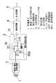
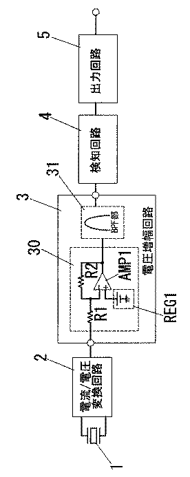
本実施形態の赤外線検知装置は、図1に示すように、焦電素子1と、電流/電圧変換回路2と、電圧増幅回路3と、検知回路4と、出力回路5とから構成され、電圧増幅回路3は容量による交流増幅部30と、1Hz付近のBPF部31とを備えている。
(参考例1)
本参考例は、図1に示す電圧増幅回路3の交流増幅部30において、図2(a)に示すように帰還用の容量素子C2に並列に不純物不拡散ポリシリコンからなる帰還回路用の抵抗R3を接続した点に特徴がある。尚その他の構成は図1の構成と同じであるので、ここでは電圧増幅回路3の構成のみ図示する。
(実施形態2)
参考例1では不純物不拡散ポリシリコンからなる帰還回路用の抵抗R3を帰還用の容量素子C2に並列接続していたが、本実施形態は図3のようなスイッチ素子Q1、Q2と容量素子C3によるスイッチトキャパシタ回路からなる帰還回路を帰還用の容量素子C2に並列接続した点に特徴がある。尚その他の構成は図1の構成と同じであるので、ここでは電圧増幅回路3のみ図示する。
Rc=1/(f×C3)で表すことができる。尚fはクロックCLKの周波数を示す。
(実施形態3)
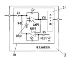
本実施形態は、動作点を安定化させるための帰還回路を用いた点に特徴がある。つまり図4に示すように電圧増幅回路3の交流増幅部30の出力VX1を演算増幅器AMP2と、抵抗R4、容量素子C4からなるローパスパスフィルタ部と、抵抗R4で帰還をかけることにより、出力VX1の動作点を安定化させるようにしたものである。尚その他の構成は図1の構成と同じであるので、ここでは電圧増幅回路3の構成のみ図示する。
(実施形態4)
本実施形態は、図2の構成において、図5に示すように交流増幅部30の帰還用の容量素子C2にさらに並列にNMOSトランジスタからなるスイッチ素子Q3を接続した点に特徴がある。尚その他の回路構成は図1に示す。
(実施形態5)
本実施形態では、図6に示すように電圧増幅回路3内において、BPF部31の後段、つまり最終段に図5で示した交流増幅部30を配置した点に特徴がある。尚その他の構成は図1の構成と同じであるので、ここでは電圧増幅回路3の構成のみ図示する。
2 電流/電圧変換回路
3 電圧増幅回路
30 交流増幅部
31 バンドパスフィルタ部
4 検知回路
5 出力回路
C1、C2 容量素子
AMP1 演算増幅器
REG1 基準電源部
Claims (1)
- 焦電素子と、該焦電素子から出力される電流信号を電圧信号に変換する電流/電圧変換回路と、該電流/電圧変換回路から出力される電圧信号を所定の周波数帯域で増幅する電圧増幅回路と、該電圧増幅回路の出力が予め定められた検知レベルを超えると検知信号を出力する出力回路とを備え、
前記電圧増幅回路は、0.1Hz〜10Hzの周波数帯に規定値以上の利得を有するように、演算増幅器の出力端と反転入力端との間に集積化可能なpFオーダーの帰還用の容量素子のみを接続するとともに前記反転入力端に集積化可能なpFオーダーの別の容量素子を直列接続し、さらに、前記演算増幅器に基準電圧を与える基準電源部を前記演算増幅器の非反転入力端とグランドとの間に接続して成る交流増幅部を有することを特徴とする赤外線検知装置。
Priority Applications (1)
| Application Number | Priority Date | Filing Date | Title |
|---|---|---|---|
| JP2010106239A JP5645247B2 (ja) | 2010-05-06 | 2010-05-06 | 赤外線検知装置 |
Applications Claiming Priority (1)
| Application Number | Priority Date | Filing Date | Title |
|---|---|---|---|
| JP2010106239A JP5645247B2 (ja) | 2010-05-06 | 2010-05-06 | 赤外線検知装置 |
Related Parent Applications (1)
| Application Number | Title | Priority Date | Filing Date |
|---|---|---|---|
| JP2004312875A Division JP4581629B2 (ja) | 2004-10-27 | 2004-10-27 | 赤外線検知装置 |
Publications (2)
| Publication Number | Publication Date |
|---|---|
| JP2010204114A JP2010204114A (ja) | 2010-09-16 |
| JP5645247B2 true JP5645247B2 (ja) | 2014-12-24 |
Family
ID=42965707
Family Applications (1)
| Application Number | Title | Priority Date | Filing Date |
|---|---|---|---|
| JP2010106239A Expired - Lifetime JP5645247B2 (ja) | 2010-05-06 | 2010-05-06 | 赤外線検知装置 |
Country Status (1)
| Country | Link |
|---|---|
| JP (1) | JP5645247B2 (ja) |
Families Citing this family (1)
| Publication number | Priority date | Publication date | Assignee | Title |
|---|---|---|---|---|
| JP2016057254A (ja) * | 2014-09-12 | 2016-04-21 | パナソニックIpマネジメント株式会社 | 赤外線検出装置 |
Family Cites Families (6)
| Publication number | Priority date | Publication date | Assignee | Title |
|---|---|---|---|---|
| JPS63273020A (ja) * | 1987-04-30 | 1988-11-10 | Sumitomo Bakelite Co Ltd | 赤外線検出器 |
| JPH04287411A (ja) * | 1991-03-15 | 1992-10-13 | Hitachi Ltd | アナログ信号レベルシフト回路 |
| JP2989320B2 (ja) * | 1991-05-28 | 1999-12-13 | ホーチキ株式会社 | 炎検出装置 |
| JPH05340807A (ja) * | 1992-06-12 | 1993-12-24 | Murata Mfg Co Ltd | 赤外線検出装置 |
| JPH09119864A (ja) * | 1994-09-28 | 1997-05-06 | Murata Mfg Co Ltd | 焦電型赤外線センサ用信号処理装置 |
| JP2001013263A (ja) * | 1999-06-30 | 2001-01-19 | Matsushita Electric Works Ltd | 赤外線検出装置 |
-
2010
- 2010-05-06 JP JP2010106239A patent/JP5645247B2/ja not_active Expired - Lifetime
Also Published As
| Publication number | Publication date |
|---|---|
| JP2010204114A (ja) | 2010-09-16 |
Similar Documents
| Publication | Publication Date | Title |
|---|---|---|
| JP3693665B2 (ja) | 容量検出回路及び容量検出方法 | |
| US10627436B2 (en) | Capacitance sensing circuits | |
| EP1448963B1 (en) | An infrared detecting circuit | |
| US20080122457A1 (en) | Capacitance difference detecting circuit | |
| CN107980208B (zh) | 信号转换电路、心率传感器和电子设备 | |
| US11863132B2 (en) | Switched capacitor amplifier circuit, voltage amplification method, and infrared sensor device | |
| JP2008008724A (ja) | 電流検出回路 | |
| CN116165420B (zh) | 一种电流检测电路及装置 | |
| TWI408378B (zh) | 電流偵測裝置 | |
| ATE344462T1 (de) | Impedanzmessschaltung und kapazitätsmessschaltung | |
| AU2005234374B2 (en) | Transconductance circuit for piezoelectric transducer | |
| JP4581629B2 (ja) | 赤外線検知装置 | |
| JP5645247B2 (ja) | 赤外線検知装置 | |
| JP6718284B2 (ja) | 信号処理回路、クーロンカウンタ回路、電子機器 | |
| JP6538532B2 (ja) | 圧電センサ | |
| CN112083212B (zh) | 电流传感器及其频率补偿方法 | |
| EP2173031B1 (en) | Amplifier arrangement, measurement arrangement and signal processing method | |
| CN103323111B (zh) | 一种用于光强检测的前置放大及量程自动转换电路 | |
| JP6241989B2 (ja) | オフセットキャンセル回路及びこの回路を用いた信号検出回路 | |
| US20150145539A1 (en) | Readout device, dual-function readout device, and detecting circuit thereof | |
| JP7743341B2 (ja) | 増幅回路及びセンサ回路 | |
| KR101091719B1 (ko) | 전력 검출기와 이를 포함하는 웨이크 업 장치 | |
| KR101001863B1 (ko) | 비접촉식 센서 회로 | |
| JP4797366B2 (ja) | 焦電型赤外線検出装置 | |
| JP5685727B2 (ja) | 赤外線検出型人体検知装置 |
Legal Events
| Date | Code | Title | Description |
|---|---|---|---|
| RD04 | Notification of resignation of power of attorney |
Free format text: JAPANESE INTERMEDIATE CODE: A7424 Effective date: 20100621 |
|
| A711 | Notification of change in applicant |
Free format text: JAPANESE INTERMEDIATE CODE: A712 Effective date: 20120113 |
|
| A131 | Notification of reasons for refusal |
Free format text: JAPANESE INTERMEDIATE CODE: A131 Effective date: 20130108 |
|
| A521 | Request for written amendment filed |
Free format text: JAPANESE INTERMEDIATE CODE: A523 Effective date: 20130311 |
|
| A131 | Notification of reasons for refusal |
Free format text: JAPANESE INTERMEDIATE CODE: A131 Effective date: 20131015 |
|
| A521 | Request for written amendment filed |
Free format text: JAPANESE INTERMEDIATE CODE: A523 Effective date: 20131216 |
|
| A02 | Decision of refusal |
Free format text: JAPANESE INTERMEDIATE CODE: A02 Effective date: 20140603 |
|
| A521 | Request for written amendment filed |
Free format text: JAPANESE INTERMEDIATE CODE: A523 Effective date: 20140903 |
|
| A911 | Transfer to examiner for re-examination before appeal (zenchi) |
Free format text: JAPANESE INTERMEDIATE CODE: A911 Effective date: 20140911 |
|
| TRDD | Decision of grant or rejection written | ||
| A01 | Written decision to grant a patent or to grant a registration (utility model) |
Free format text: JAPANESE INTERMEDIATE CODE: A01 Effective date: 20141007 |
|
| A711 | Notification of change in applicant |
Free format text: JAPANESE INTERMEDIATE CODE: A711 Effective date: 20141009 |
|
| A61 | First payment of annual fees (during grant procedure) |
Free format text: JAPANESE INTERMEDIATE CODE: A61 Effective date: 20141030 |
|
| R150 | Certificate of patent or registration of utility model |
Ref document number: 5645247 Country of ref document: JP Free format text: JAPANESE INTERMEDIATE CODE: R150 |
|
| EXPY | Cancellation because of completion of term |