US11326480B2 - Rocker arm assembly - Google Patents
Rocker arm assembly Download PDFInfo
- Publication number
- US11326480B2 US11326480B2 US17/371,240 US202117371240A US11326480B2 US 11326480 B2 US11326480 B2 US 11326480B2 US 202117371240 A US202117371240 A US 202117371240A US 11326480 B2 US11326480 B2 US 11326480B2
- Authority
- US
- United States
- Prior art keywords
- arm assembly
- rocker arm
- socket
- pad
- upper wall
- Prior art date
- Legal status (The legal status is an assumption and is not a legal conclusion. Google has not performed a legal analysis and makes no representation as to the accuracy of the status listed.)
- Active
Links
Images




Classifications
-
- F—MECHANICAL ENGINEERING; LIGHTING; HEATING; WEAPONS; BLASTING
- F01—MACHINES OR ENGINES IN GENERAL; ENGINE PLANTS IN GENERAL; STEAM ENGINES
- F01L—CYCLICALLY OPERATING VALVES FOR MACHINES OR ENGINES
- F01L1/00—Valve-gear or valve arrangements, e.g. lift-valve gear
- F01L1/12—Transmitting gear between valve drive and valve
- F01L1/18—Rocking arms or levers
-
- F—MECHANICAL ENGINEERING; LIGHTING; HEATING; WEAPONS; BLASTING
- F01—MACHINES OR ENGINES IN GENERAL; ENGINE PLANTS IN GENERAL; STEAM ENGINES
- F01L—CYCLICALLY OPERATING VALVES FOR MACHINES OR ENGINES
- F01L1/00—Valve-gear or valve arrangements, e.g. lift-valve gear
- F01L1/12—Transmitting gear between valve drive and valve
- F01L1/14—Tappets; Push rods
- F01L1/146—Push-rods
-
- F—MECHANICAL ENGINEERING; LIGHTING; HEATING; WEAPONS; BLASTING
- F01—MACHINES OR ENGINES IN GENERAL; ENGINE PLANTS IN GENERAL; STEAM ENGINES
- F01L—CYCLICALLY OPERATING VALVES FOR MACHINES OR ENGINES
- F01L1/00—Valve-gear or valve arrangements, e.g. lift-valve gear
- F01L1/12—Transmitting gear between valve drive and valve
- F01L1/18—Rocking arms or levers
- F01L1/181—Centre pivot rocking arms
-
- F—MECHANICAL ENGINEERING; LIGHTING; HEATING; WEAPONS; BLASTING
- F01—MACHINES OR ENGINES IN GENERAL; ENGINE PLANTS IN GENERAL; STEAM ENGINES
- F01L—CYCLICALLY OPERATING VALVES FOR MACHINES OR ENGINES
- F01L1/00—Valve-gear or valve arrangements, e.g. lift-valve gear
- F01L1/12—Transmitting gear between valve drive and valve
- F01L1/18—Rocking arms or levers
- F01L1/181—Centre pivot rocking arms
- F01L1/182—Centre pivot rocking arms the rocking arm being pivoted about an individual fulcrum, i.e. not about a common shaft
-
- F—MECHANICAL ENGINEERING; LIGHTING; HEATING; WEAPONS; BLASTING
- F01—MACHINES OR ENGINES IN GENERAL; ENGINE PLANTS IN GENERAL; STEAM ENGINES
- F01L—CYCLICALLY OPERATING VALVES FOR MACHINES OR ENGINES
- F01L1/00—Valve-gear or valve arrangements, e.g. lift-valve gear
- F01L1/02—Valve drive
- F01L1/04—Valve drive by means of cams, camshafts, cam discs, eccentrics or the like
- F01L1/047—Camshafts
- F01L2001/054—Camshafts in cylinder block
-
- F—MECHANICAL ENGINEERING; LIGHTING; HEATING; WEAPONS; BLASTING
- F01—MACHINES OR ENGINES IN GENERAL; ENGINE PLANTS IN GENERAL; STEAM ENGINES
- F01L—CYCLICALLY OPERATING VALVES FOR MACHINES OR ENGINES
- F01L2305/00—Valve arrangements comprising rollers
- F01L2305/02—Mounting of rollers
-
- F—MECHANICAL ENGINEERING; LIGHTING; HEATING; WEAPONS; BLASTING
- F01—MACHINES OR ENGINES IN GENERAL; ENGINE PLANTS IN GENERAL; STEAM ENGINES
- F01L—CYCLICALLY OPERATING VALVES FOR MACHINES OR ENGINES
- F01L2810/00—Arrangements solving specific problems in relation with valve gears
- F01L2810/02—Lubrication
Definitions
- Conventional engine valvetrain systems known in the art typically include one or more camshafts in rotational communication with a crankshaft supported in a block, one or more intake and exhaust valves supported in a cylinder head, and one or more intermediate members for transforming rotational motion of lobes on the camshaft into linear motion of the valves.
- the valves are used to regulate flow through respective intake and exhaust ports defined in the cylinder head and in fluid communication with a combustion chamber.
- the valves each have a head configured to seal against a valve seat in the cylinder head, and a stem extending therefrom.
- valve stem is typically supported for linear motion by a valve guide, which is attached to the cylinder head such that the valve stem extends through the valve guide and travels therealong in response to engagement from the intermediate member.
- a compression spring is typically disposed about the valve stem and arranged between the cylinder head and a spring retainer operatively coupled to the valve stem. The spring provides a force that urges the valve toward a closed position.
- cam-in-block One engine configuration, particularly popular in V-engines, is known as “cam-in-block”, in which the camshaft is supported in the block.
- cam-in-block engines utilize an “overhead valve” (OHV) arrangement, in which the valves are arranged above (i.e. overhead) the combustion chamber.
- OOV overhead valve
- the intermediate member may include a cam follower, a pushrod, and a rocker arm.
- the cam follower commonly referred to as a lifter, engages the camshaft lobe and moves in a linear path according to a profile of the camshaft lobe. Motion of the cam follower is transferred through the pushrod to the rocker arm, which is supported on the cylinder head.
- the rocker arm extends between and engages the pushrod and the valve stem.
- the intermediate member transforms rotation from the lobes into linear movement of the valve between two different positions, commonly referred to as “valve opened” and “valve closed”.
- valve opened potential energy from the loaded spring holds the valve head sealed against the valve seat.
- valve opened the intermediate member transforms the linear movement to compress the spring, thereby un-sealing the valve head from the valve seat so as to allow gasses to flow into, or out of, the combustion chamber.
- the rocker arm assembly further includes a trunnion body and a bearing.
- the trunnion body is disposed in each of the pivot bores and defines a mounting bore configured for receiving a fastener.
- the bearing is supported on the trunnion body and is disposed in each of the pivot bores for facilitating pivoting movement between the rocker body and the trunnion body.
- FIG. 2 is a perspective view of the valvetrain of FIG. 1 including a rocker arm assembly, a valve, and a pushrod.
- FIG. 3 is a perspective view of the rocker arm assembly of FIG. 2 .
- FIG. 6 is a bottom perspective view of the rocker body of FIG. 5 .
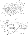
- FIG. 7 is a side view of the rocker body of FIG. 6 .
- FIG. 9 is a cross-sectional perspective view of the rocker body of FIG. 8 taken along line 9 - 9 .
- FIG. 10 is a perspective view of the trunnion body of FIG. 5 .
- FIG. 12 is a perspective view of a second embodiment of a rocker arm assembly and a fastener.
- FIG. 13 is a front view of the rocker arm assembly of FIG. 12 including a rocker body and a trunnion body.
- FIG. 14 is a bottom perspective view of the rocker body of FIG. 13 .
- FIG. 15 is a side view of the rocker body of FIG. 14 .
- FIG. 16 is a top view of the rocker body of FIG. 14 .
- FIG. 17 is a cross-sectional view of the rocker body of FIG. 16 taken along line 17 - 17 .
- the cylinder head assembly 50 includes a cylinder head 52 , generally formed from a cast metal such as aluminum or iron, which defines one or more intake ports 54 and one or more exhaust ports 56 that route combustion products into and out of a combustion chamber.
- the cylinder head assembly 50 further comprises a valvetrain, generally indicated at 58 , which typically includes one or more camshafts (not shown) in rotational communication with a crankshaft supported in a cylinder block, one or more intake valves 60 A and one or more exhaust valves 60 B supported in the cylinder head 52 , and one or more intermediate members for transforming rotational motion of lobes on the camshaft into linear motion of the valves 60 A, 60 B.
- the valves 60 A, 60 B each have a head 62 and a stem 64 extending therefrom.
- the head 62 is configured to seal against a valve seat 66 in the cylinder head 52 , and the stem 64 is supported for linear motion by a valve guide (not shown) attached to the cylinder head 52 such that the valve stem 64 extends through the valve guide and travels therealong in response to engagement from the intermediate member.
- a valve spring 68 is typically disposed about the valve stem 64 and arranged between the cylinder head 52 and a spring retainer 70 operatively coupled to the valve stem 64 . The spring 68 provides a force that urges the valve 60 toward a closed position.
- the one or more intermediate members that cooperate with the camshaft may include a lifter (not shown) in contact with the camshaft lobe, a pushrod 72 , and a rocker arm assembly 100 .
- the rocker arm assembly 100 is supported on a pedestal 76 formed in the cylinder head 52 and coupled thereto with a fastener 78 .
- FIG. 1 shows the rocker arm assembly 100 oriented in an installed position in the cylinder head 52 .
- the pushrod 72 has two ball ends 74 and is arranged between the rocker arm assembly 100 and the lifter to effect pivoting movement of the rocker arm assembly 100 that actuates the valve 60 .
- the rocker arm assembly 100 cooperates with the valve 60 , the pushrod 72 , the lifter, and the camshaft lobe to regulate the flow of combustion products into and out of the combustion chamber during operation of the internal combustion engine.
- FIG. 2 a portion of the valvetrain 58 is shown, specifically, the rocker arm assembly 100 , the pushrod 72 , the valve 60 , and the fastener 78 .
- the rocker arm assembly 100 defines a pivot axis 102 about which the rocker arm assembly 100 pivots in response to forces from the valve 60 and the pushrod 72 . Force from the lobe of the camshaft displaces the pushrod 72 toward the rocker arm assembly 100 , which causes the rocker arm assembly 100 to pivot. Pivoting of the rocker arm assembly 100 displaces the valve 60 , which compresses the spring 68 ( FIG. 1 ). As the combustion cycle continues a valve closing event is reached, where force from the spring 68 acts toward the rocker arm assembly 100 to close the valve 60 , which pivots the rocker arm assembly 100 and displaces the pushrod 72 toward the lobe of the camshaft.
- the rocker arm assembly 100 comprises a rocker body 104 having a pad end 106 and a socket end 108 .
- the socket end 108 is spaced in a longitudinal direction relative to the pad end 106 such that the socket end 108 and the pad end 106 are on opposite sides of the pivot axis 102 .
- the arrangement of the pad end 106 and the socket end 108 across the pivot axis 102 is such that movement of one end results in coordinated movement of the other, e.g. as the socket end 108 moves in an upward direction the pad end 106 moves in a downward direction, and vice versa.
- the rocker body 104 generally includes an upper wall 110 and two ears 112 .
- the upper wall 110 is arranged above the pivot axis 102 and defines an aperture 114 extending therethrough.
- the ears 112 each extend generally downward from laterally opposing sides of the upper wall 110 when the rocker arm assembly 100 is oriented in an installed position. In some configurations, the ears 112 may be angled away from perpendicular relative to the pivot axis 102 .
- Each ear 112 defines a pivot bore 120 that is coaxial with the pivot axis 102 .
- Each pivot bore 120 extends through the respective ear 112 and shares a common diameter with the pivot bore 120 on the opposing ear 112 .
- the pivot bore 120 may have an oblong contact pattern with a bearing assembly disposed in the pivot bore 120 .
- the pad 130 and the socket 134 are shown with the convex pad surface 132 and the concave socket surface 136 opening away from the upper wall 110 .
- the convex pad surface 132 and the concave socket surface 136 are each generally directed in the same direction as the ears 112 extending from the upper wall 110 .
- the pad 130 protrudes from the pad end wall 116 in a direction away from the socket end 108 thereby increasing a length of the pad 130 in the longitudinal direction. Additionally, the pad 130 may protrude from the pad end wall 116 in a direction toward the socket end 108 increasing the length of the pad 130 in the longitudinal direction further still.
- the convex pad surface 132 has a generally rectangular shape that protrudes from the perimeter wall 122 away from the upper wall 110 .
- the rectangular shape of the convex pad surface 132 is curved about an axis that is generally parallel with the pivot axis 102 and spaced toward the upper wall 110 from the convex pad surface 132 .
- the configuration of the convex pad surface 132 is such that the curve is in a longitudinal direction in order to facilitate sliding contact with the valve stem 64 as the rocker body 104 pivots about the pivot axis 102 .
- rocker arm assembly 100 is subject to large forces from both the valve spring 68 and the pushrod 72 .
- strength of the rocker body 104 is important.
- One aspect that increases strength is forming the rocker body 104 such that material is located where it is most needed.
- One example of this is forming the rocker body 104 such that the aperture 114 is smaller than the cavity 154 .
- the aperture width 146 is less than the cavity width 156
- the aperture length 148 is less than the cavity length 158 .
- an undercut region 160 may be formed on the rocker body 104 , which is visible in FIGS. 6 and 9 .
- the undercut region 160 may include a region at least partially above the pad 130 , or between the convex pad surface 132 and the bottom surface 152 of the upper wall 110 .
- the ball end 74 engages the concave socket surface 136 such that lubricant flowing out of the pushrod 72 is forced into the lubrication port 140 , while a smaller amount of lubricant is pushed between the ball end 74 and the concave socket surface 136 .
- the lubrication passage 142 may be one or more passages that intersect with the lubrication port 140 or each other. Further, either or both of the lubrication port 140 and the lubrication passage 142 may be formed during manufacturing as through holes and subsequently capped on one side.
- FIG. 7 several measurements of portions of the rocker body 104 are shown. Specifically, the measurements show the arrangement and relative spacing of particular elements, as will be discussed.
- an uppermost surface of the upper wall 110 is spaced at a first height 162 from the pivot axis 102 (shown here as a point positioned in the center of the pivot bore 120 ).
- the uppermost surface is the top surface 150 of the upper wall 110 and, as such, the first height 162 is a vertical measurement between the top surface 150 and the pivot axis 102 .
- the pad 130 and the socket 134 are each spaced at respective heights from the pivot axis 102 .
- the pad 130 is spaced at a pad height 164 from the pivot axis 102 , which is a vertical measurement between the convex pad surface 132 and the pivot axis 102 .
- the socket 134 is spaced at a socket height 166 from the pivot axis 102 , which is a vertical measurement between the opening of the socket 134 and the pivot axis 102 .
- the top of the rocker body 104 is best shown in FIGS. 2, 3, 5, and 8 , where a rib 168 is defined on the top surface 150 of the upper wall 110 .
- the rib 168 is formed into the upper wall 110 as a localized area of reduced thickness.
- the rib 168 extends across the upper wall 110 in a direction generally parallel to the pivot axis 102 .
- the rib may be further defined as a first rib 168 A and a second rib 168 B.
- the first rib 168 A is positioned on the top surface 150 of the upper wall 110 between the pad end 106 and the pivot axis 102 .
- the second rib 168 B is positioned on the top surface 150 of the upper wall 110 between the socket end 108 and the pivot axis 102 .
- Each rib 168 A, 168 B includes two sub-surfaces that are generally perpendicular to each other and connected with a radius therebetween. The sub-surfaces are also at an angle to the top surface 150 such that the ribs 168 A, 168 B are recessed into the upper wall 110 .
- rocker body 104 having the features described herein.
- one embodiment of the rocker body 104 may be manufactured with a stamping process using a tool (not shown), which includes a die and a punch.
- the die forms the outside surfaces (e.g. the top surface 150 , and ribs 168 A, 168 B) while the punch forms the inside surfaces (e.g. the bottom surface 152 , and the cavity 154 ).
- the punch and die are brought together with raw material stock therebetween, thereby displacing the raw material into the shape of the rocker body 104 .
- the punch forms the features of the rocker body 104 that are oriented toward the cylinder head 52 , while the die forms the features that are oriented away from the cylinder head 52 .
- Alternative manufacturing processes may similarly be employed, for example additive processes such as casting, forging, 3D printing, and the like, and alternatively subtractive processes where raw material is removed from a billet via milling, drilling, etc.
- the trunnion body 124 is shown in a perspective view and a side view.
- the trunnion body 124 includes a mounting segment 170 and two trunnion arms 172 coupled thereto.
- Each of the trunnion arms 172 has a non-circular profile and protrudes from an opposing side of the mounting segment 170 in a direction generally parallel with the pivot axis 102 of the rocker arm assembly 100 .
- the mounting segment 170 has a pedestal engaging face 174 and a fastener boss 176 arranged opposite the pedestal engaging face 174 .
- the pedestal engaging face 174 may be flat or curved, as the case may be.
- a rocker stand (not shown) may be arranged on top of the pedestal 76 to receive the pedestal engaging face 174 .
- the pedestal engaging face 174 is configured to engage the cylinder head 52 on a pedestal 76 having a curved face.
- the mounting bore 126 is defined in the mounting segment 170 and extends between the fastener boss 176 and the pedestal engaging face 174 .
- the fastener 78 is disposed in the mounting bore 126 to clamp the trunnion body 124 to the pedestal 76 .
- the bearing 128 is used to reduce friction between the rocker body 104 and the trunnion body 124 .
- the bearing 128 is supported by the trunnion arms 172 to facilitate pivoting movement between the rocker body 104 and the trunnion body 124 .
- the forces acting on the rocker arm assembly 100 however do not act on all sides of the bearing 128 equally, that is to say that the forces are generally oriented away from the cylinder head 52 .
- the non-circular profile of the trunnion arms 172 includes a thrust surface 178 and an anti-thrust surface 180 .
- the thrust surface 178 is configured to receive a majority of the forces acting between the rocker body 104 and the trunnion body 124 and is therefore arranged facing toward the cylinder head 52 . As such, the anti-thrust surface 180 receives a smaller proportion of these forces and is arranged facing away from the cylinder head 52 .
- a third surface 182 may be positioned between the thrust surface 178 and the anti-thrust surface 180 . The third surface 182 does not contact the bearing 128 and may be flat or curved.
- the thrust surface 178 is curved to increase the engagement between the trunnion arm 172 and the bearing 128 to support relatively larger forces and the anti-thrust surface 180 is angled to reduce contact between the trunnion arm 172 and the bearing 128 .
- the anti-thrust surface 180 includes two faces 180 A, 180 B that meet at a vertex 188 spaced from the pivot axis 102 .
- the vertex 188 may have a slight radius that connects a first face 180 A to a second face 180 B.
- Contact of the anti-thrust surface 180 and the bearing 128 may be further reduced by angling an outer face 180 C inward toward the mounting segment 170 such that the vertex 188 of the anti-thrust surface 180 has a length less than a length of the thrust surface 178 of the trunnion arm 172 .
- the anti-thrust surface 180 may also be smaller than the thrust surface 178 .
- the anti-thrust surface 180 has a width 184 measured at a widest point and in a direction perpendicular to the pivot axis 102 .
- the thrust surface 178 has a trunnion diameter 186 measured as the diameter of a circle centered on the pivot axis 102 and aligned with the curve of the thrust surface 178 .
- the width 184 of the anti-thrust surface 180 may be less than the trunnion diameter 186 of the thrust surface 178 .
- the bearing 128 may be realized as first and second bearings, shown generally in FIG. 4 .
- the first and second bearings 128 are each supported for rotation on the trunnion body 124 and disposed in each of the pivot bores 120 .
- the bearing 128 may be realized as a roller bearing assembly.
- the second bearing 128 may include an outer race 190 , an inner race 192 , and a plurality of rollers 194 .
- the outer race 190 is adapted to engage the pivot bore 120 and the inner race 192 is adapted to engage either of the trunnion arms 172 .
- the plurality of rollers 194 are arranged between the outer race 190 and the inner race 192 . The rollers 194 reduce friction and help distribute load between the inner race 192 and the outer race 190 during operation.
- first and second bearings 128 may include the rollers 194 shown having a cylindrical configuration or may be a ball bearing that includes rollers having a spherical configuration (not shown).
- the bearing 128 may be realized as hydrodynamic journal bearings (not shown), which are rotatably supported on the trunnion arms 172 .
- rocker arm assembly 100 ′ may be similar to that previously described with like numerals (plus a prime symbol e.g. 100 ′) corresponding to like components, and any disclosure common to the corresponding components may be considered omitted in the interest of brevity should not be construed as limiting.
- the second embodiment of the rocker arm assembly 100 ′ comprises a rocker body 104 ′ having a pad end 106 ′ and a socket end 108 ′.
- the socket end 108 ′ is spaced in a longitudinal direction relative to the pad end 106 ′ such that the socket end 108 ′ and the pad end 106 ′ are on opposite sides of the pivot axis 102 ′.
- the arrangement of the pad end 106 ′ and the socket end 108 ′ across the pivot axis 102 ′ is such that movement of one end results in coordinated movement of the other, e.g. as the socket end 108 ′ moves in an upward direction the pad end 106 ′ moves in a downward direction, and vice versa.
- the rocker body 104 ′ generally includes an upper wall 110 ′ and two ears 112 ′.
- the upper wall 110 ′ is arranged above the pivot axis 102 ′ and defines an aperture 114 ′ extending therethrough.
- the ears 112 ′ each extend downwardly from laterally opposing sides of the upper wall 110 ′ when the rocker arm assembly 100 ′ is oriented in an installed position.
- Each ear 112 ′ defines a pivot bore 120 ′ that is coaxial with the pivot axis 102 ′.
- Each pivot bore 120 ′ extends through the respective ear 112 ′ and shares a common diameter with the pivot bore 120 ′ on the opposing ear 112 ′.
- the rocker body 104 ′ may further include a pad end wall portion 116 ′ and a socket end wall portion 118 ′ arranged as the respective pad end 106 ′ and socket end 108 ′.
- the pad end wall portion 116 ′ and the socket end wall portion 118 ′ each extend downwardly from longitudinally opposing ends of the upper wall 110 ′.
- the pad end wall portion 116 ′ and the socket end wall portion 118 ′ may cooperate with the ears 112 ′ to define a perimeter wall 122 ′.
- the perimeter wall 122 ′ extends downwardly from a periphery of the upper wall 110 ′.
- the upper wall 110 ′ and the perimeter wall 122 ′ may be integrally formed with various general shapes.
- the upper wall 110 ′ is generally rectangular and the perimeter wall 122 ′ is formed on each of the four sides.
- the delineation between the upper wall 110 ′ and the perimeter wall 122 ′ may vary.
- the rocker body 104 ′ is shown with a radius 144 arranged between the upper wall 110 ′ and the perimeter wall 122 ′ such that the upper wall 110 ′ gradually curves into the perimeter wall 122 ′.
- the radius 144 ′ may be larger or smaller as is necessary for specific packaging constraints.
- the rocker body 104 ′ includes a pad 130 ′ formed on the pad end wall portion 116 ′ and having a convex pad surface 132 ′ oriented away from the upper wall 110 ′ for engaging the valve stem 64 .
- the rocker body 104 ′ further includes a socket 134 ′ formed on the socket end wall portion 118 ′ and having a concave socket surface 136 ′ oriented away from the upper wall 110 ′ for engaging the ball end 74 of the pushrod 72 .
- the pad 130 ′ protrudes from the pad end wall 116 ′ in a direction away from the socket end 108 ′ thereby increasing a length of the pad 130 ′ in the longitudinal direction.
- the pad 130 ′ tapers along its length to a width that is less than the rocker body 104 ′.
- the convex pad surface 132 ′ may have a generally elongated shape that protrudes from the pad end wall portion 116 ′.
- the elongated shape of the convex pad surface 132 ′ is curved about an axis that is generally parallel with the pivot axis 102 ′ and spaced toward the upper wall 110 ′ from the convex pad surface 132 ′.
- the convex pad surface 132 ′ and the concave socket surface 136 ′ are each generally directed in the same direction as the ears 112 ′ extending from the upper wall 110 ′.
- the configuration of the convex pad surface 132 ′ is such that the curve is in a longitudinal direction in order to facilitate sliding contact with the valve stem 64 as the rocker body 104 ′ pivots about the pivot axis 102 ′.
- the bottom-side perspective view of the rocker body 104 ′ shows the convex pad surface 132 ′ and the socket 134 ′, as well as the ears 112 ′ and perimeter wall 122 ′.
- a bottom surface 152 ′ of the upper wall 110 ′ is adjacent to and cooperates with the perimeter wall 122 ′, which may define a cavity 154 ′ of the rocker body 104 ′.
- lubrication port 140 ′ and lubrication passage 142 ′ are shown in cross-section to illustrate the path that a lubricant (such as oil, grease, etc.) can follow. Similar to above, lubricant may be supplied through a lumen (not shown) defined in the pushrod 72 .
- the pad end wall portion 116 ′ and the pad 130 ′ may include a channel 196 ′ formed on an upward facing surface generally positioned along a longitudinal centerline of the rocker body 104 ′.
- the channel 196 ′ is configured to collect lubricant that may be splashed onto the rocker body 104 ′ and funnel the collected lubricant to the valve stem 64 .
- the size and shape of the channel 196 ′ may vary according to the amount of lubricant expected to be splashed as well as the lubrication needs of the valve stem 64 .
- the channel 196 ′ has a generally flat surface, however the channel 196 ′ may include additional features or surfaces usable during the manufacturing process for fixturing and/or alignment.
Landscapes
- Engineering & Computer Science (AREA)
- Mechanical Engineering (AREA)
- General Engineering & Computer Science (AREA)
- Valve-Gear Or Valve Arrangements (AREA)
Priority Applications (1)
| Application Number | Priority Date | Filing Date | Title |
|---|---|---|---|
| US17/371,240 US11326480B2 (en) | 2020-07-09 | 2021-07-09 | Rocker arm assembly |
Applications Claiming Priority (2)
| Application Number | Priority Date | Filing Date | Title |
|---|---|---|---|
| US202063049834P | 2020-07-09 | 2020-07-09 | |
| US17/371,240 US11326480B2 (en) | 2020-07-09 | 2021-07-09 | Rocker arm assembly |
Publications (2)
| Publication Number | Publication Date |
|---|---|
| US20220010692A1 US20220010692A1 (en) | 2022-01-13 |
| US11326480B2 true US11326480B2 (en) | 2022-05-10 |
Family
ID=79172360
Family Applications (1)
| Application Number | Title | Priority Date | Filing Date |
|---|---|---|---|
| US17/371,240 Active US11326480B2 (en) | 2020-07-09 | 2021-07-09 | Rocker arm assembly |
Country Status (2)
| Country | Link |
|---|---|
| US (1) | US11326480B2 (fr) |
| WO (1) | WO2022011202A1 (fr) |
Citations (20)
| Publication number | Priority date | Publication date | Assignee | Title |
|---|---|---|---|---|
| US4858575A (en) * | 1988-03-01 | 1989-08-22 | David Fittro | Rocker arm bearing assembly |
| US4944257A (en) | 1989-09-27 | 1990-07-31 | Henley Manufacturing Holding Company, Inc. | Cold-formed rocker arm with bearing flanges and splash plate |
| US5027191A (en) | 1989-05-11 | 1991-06-25 | Westinghouse Electric Corp. | Cavity-down chip carrier with pad grid array |
| US5063889A (en) | 1990-08-24 | 1991-11-12 | Henley Manufacturing Holding Company, Inc. | Rocker arm with lubrication provisions |
| US5074261A (en) * | 1991-01-14 | 1991-12-24 | The Torrington Company | Rocker arm assembly |
| US5313916A (en) * | 1993-07-30 | 1994-05-24 | The Torrington Company | Rocker arm assembly |
| US5433178A (en) * | 1994-07-25 | 1995-07-18 | The Torrington Company | Rocker arm assembly and method of assembly |
| US5437209A (en) * | 1993-09-30 | 1995-08-01 | The Torrington Company | Rocker arm assembly |
| JPH09125917A (ja) | 1995-10-27 | 1997-05-13 | Kubota Corp | 頭上弁エンジンの動弁装置 |
| US6227156B1 (en) | 1999-02-19 | 2001-05-08 | Ina Walzlager Schaeffler Ohg | Rocker arm for a valve train of an internal combustion engine |
| US6293168B1 (en) * | 1999-10-06 | 2001-09-25 | The Torrington Company | Stamped rocker arms for machines such as internal combustion engines |
| US20030140878A1 (en) * | 2002-01-31 | 2003-07-31 | Ina-Schaeffler Kg | Rocker arm arrangement for internal combustion engine |
| US6612199B2 (en) | 2001-01-19 | 2003-09-02 | E & E Manufacturing Company, Inc. | Rocker arm assembly |
| US7185618B1 (en) | 2006-01-12 | 2007-03-06 | Gentek Technologies Marketing Inc. | Sheet metal rocker arm with integrally formed cross member |
| US20080098971A1 (en) * | 2006-10-31 | 2008-05-01 | Schaeffler Kg | Rocker arm assembly for radial and axial loads |
| US20090000583A1 (en) * | 2007-06-27 | 2009-01-01 | The Timken Company | Segmented rolling element bearing |
| US20120060781A1 (en) * | 2010-09-13 | 2012-03-15 | Schaeffler Technologies Gmbh & Co. Kg | Rocker arm assembly with an anti-inversion feature |
| US8573170B2 (en) | 2010-09-13 | 2013-11-05 | Schaeffler Technologies AG & Co. KG | Rocker arm assembly with integrated support pin anti-inversion feature |
| JP2016125348A (ja) | 2014-12-26 | 2016-07-11 | 株式会社オティックス | ロッカアーム及びロッカーアームの製造方法 |
| US20180216501A1 (en) * | 2017-02-01 | 2018-08-02 | GM Global Technology Operations LLC | Mass-efficient rocking component |
-
2021
- 2021-07-09 WO PCT/US2021/040983 patent/WO2022011202A1/fr not_active Ceased
- 2021-07-09 US US17/371,240 patent/US11326480B2/en active Active
Patent Citations (21)
| Publication number | Priority date | Publication date | Assignee | Title |
|---|---|---|---|---|
| US4858575A (en) * | 1988-03-01 | 1989-08-22 | David Fittro | Rocker arm bearing assembly |
| US5027191A (en) | 1989-05-11 | 1991-06-25 | Westinghouse Electric Corp. | Cavity-down chip carrier with pad grid array |
| US4944257A (en) | 1989-09-27 | 1990-07-31 | Henley Manufacturing Holding Company, Inc. | Cold-formed rocker arm with bearing flanges and splash plate |
| US5063889A (en) | 1990-08-24 | 1991-11-12 | Henley Manufacturing Holding Company, Inc. | Rocker arm with lubrication provisions |
| US5074261A (en) * | 1991-01-14 | 1991-12-24 | The Torrington Company | Rocker arm assembly |
| US5313916A (en) * | 1993-07-30 | 1994-05-24 | The Torrington Company | Rocker arm assembly |
| US5437209A (en) * | 1993-09-30 | 1995-08-01 | The Torrington Company | Rocker arm assembly |
| US5433178A (en) * | 1994-07-25 | 1995-07-18 | The Torrington Company | Rocker arm assembly and method of assembly |
| JPH09125917A (ja) | 1995-10-27 | 1997-05-13 | Kubota Corp | 頭上弁エンジンの動弁装置 |
| US6227156B1 (en) | 1999-02-19 | 2001-05-08 | Ina Walzlager Schaeffler Ohg | Rocker arm for a valve train of an internal combustion engine |
| US6293168B1 (en) * | 1999-10-06 | 2001-09-25 | The Torrington Company | Stamped rocker arms for machines such as internal combustion engines |
| US6612199B2 (en) | 2001-01-19 | 2003-09-02 | E & E Manufacturing Company, Inc. | Rocker arm assembly |
| US20030140878A1 (en) * | 2002-01-31 | 2003-07-31 | Ina-Schaeffler Kg | Rocker arm arrangement for internal combustion engine |
| US7185618B1 (en) | 2006-01-12 | 2007-03-06 | Gentek Technologies Marketing Inc. | Sheet metal rocker arm with integrally formed cross member |
| US20080098971A1 (en) * | 2006-10-31 | 2008-05-01 | Schaeffler Kg | Rocker arm assembly for radial and axial loads |
| US20090000583A1 (en) * | 2007-06-27 | 2009-01-01 | The Timken Company | Segmented rolling element bearing |
| US20120060781A1 (en) * | 2010-09-13 | 2012-03-15 | Schaeffler Technologies Gmbh & Co. Kg | Rocker arm assembly with an anti-inversion feature |
| US8573170B2 (en) | 2010-09-13 | 2013-11-05 | Schaeffler Technologies AG & Co. KG | Rocker arm assembly with integrated support pin anti-inversion feature |
| JP2016125348A (ja) | 2014-12-26 | 2016-07-11 | 株式会社オティックス | ロッカアーム及びロッカーアームの製造方法 |
| US20170350281A1 (en) | 2014-12-26 | 2017-12-07 | Otics Corporation | Rocker arm and method of manufacturing the rocker arm |
| US20180216501A1 (en) * | 2017-02-01 | 2018-08-02 | GM Global Technology Operations LLC | Mass-efficient rocking component |
Non-Patent Citations (1)
| Title |
|---|
| International Search Report and Written Opinion of the International Searching Authority for PCT International Application No. PCT/US2021/040983 dated Oct. 27, 2021. |
Also Published As
| Publication number | Publication date |
|---|---|
| WO2022011202A1 (fr) | 2022-01-13 |
| US20220010692A1 (en) | 2022-01-13 |
Similar Documents
| Publication | Publication Date | Title |
|---|---|---|
| US4697473A (en) | Rocker arm with cam-contacting roller | |
| US6347606B1 (en) | Valve operating system in internal combustion engine | |
| US6412460B1 (en) | Valve operating system in internal combustion engine | |
| JP2000240412A (ja) | 内燃機関の動弁装置 | |
| US6467444B2 (en) | Valve operating system in internal combustion engine | |
| US11326480B2 (en) | Rocker arm assembly | |
| CN204572103U (zh) | 摇臂组件及内燃机 | |
| US6347607B2 (en) | Valve operating system in internal combustion engine | |
| US5492085A (en) | Supported pushrod for internal combustion engines | |
| KR100872640B1 (ko) | 캠 샤프트 마찰 저감을 위한 오일 공급 통로 | |
| JP2580163Y2 (ja) | 動弁装置の潤滑構造 | |
| US10450902B2 (en) | Finger follower assembly for use in a valvetrain of an internal combustion engine | |
| EP1013898B1 (fr) | Dispositif de commande de soupape pour moteur à combustion interne | |
| JP7721961B2 (ja) | 内燃機関 | |
| JP2006063955A (ja) | エンジン動弁系の潤滑装置 | |
| JPH0791220A (ja) | 内燃機関の潤滑装置 | |
| JPS6014885Y2 (ja) | 内燃機関の動弁機構 | |
| JPS6139051Y2 (fr) | ||
| JPH0561401U (ja) | 内燃機関の動弁機構 | |
| JP2003307104A (ja) | カムフォロワ | |
| JPS6212807Y2 (fr) | ||
| JP2001193427A (ja) | 内燃機関の動弁装置 | |
| JP2000240418A (ja) | 内燃機関の動弁装置 | |
| JP2001193425A (ja) | 内燃機関の動弁装置 | |
| JP2001193420A (ja) | 内燃機関の動弁装置 |
Legal Events
| Date | Code | Title | Description |
|---|---|---|---|
| FEPP | Fee payment procedure |
Free format text: ENTITY STATUS SET TO UNDISCOUNTED (ORIGINAL EVENT CODE: BIG.); ENTITY STATUS OF PATENT OWNER: LARGE ENTITY |
|
| STPP | Information on status: patent application and granting procedure in general |
Free format text: DOCKETED NEW CASE - READY FOR EXAMINATION |
|
| AS | Assignment |
Owner name: GREAT ROCK CAPITAL PARTNERS MANAGEMENT, LLC, AS AGENT, CONNECTICUT Free format text: INTELLECTUAL PROPERTY SECURITY AGREEMENT;ASSIGNOR:GT TECHNOLOGIES, INC.;REEL/FRAME:058301/0356 Effective date: 20211203 |
|
| AS | Assignment |
Owner name: BANK OF AMERICA, N.A., AS AGENT, MICHIGAN Free format text: INTELLECTUAL PROPERTY SECURITY AGREEMENT;ASSIGNOR:GT TECHNOLOGIES, INC.;REEL/FRAME:058320/0191 Effective date: 20211203 |
|
| AS | Assignment |
Owner name: PATRIOT CAPITAL III SBIC, L.P., MARYLAND Free format text: SECURITY AGREEMENT;ASSIGNOR:GT TECHNOLOGIES, INC.;REEL/FRAME:058548/0768 Effective date: 20211203 |
|
| AS | Assignment |
Owner name: GT TECHNOLOGIES, INC., MICHIGAN Free format text: ASSIGNMENT OF ASSIGNORS INTEREST;ASSIGNORS:BRUNE, JOHN E.;SMITH, SCOTT PAUL;LANDIS, DENNIS;SIGNING DATES FROM 20211217 TO 20211220;REEL/FRAME:059234/0261 |
|
| STPP | Information on status: patent application and granting procedure in general |
Free format text: NOTICE OF ALLOWANCE MAILED -- APPLICATION RECEIVED IN OFFICE OF PUBLICATIONS |
|
| STPP | Information on status: patent application and granting procedure in general |
Free format text: PUBLICATIONS -- ISSUE FEE PAYMENT VERIFIED |
|
| STCF | Information on status: patent grant |
Free format text: PATENTED CASE |
|
| FEPP | Fee payment procedure |
Free format text: MAINTENANCE FEE REMINDER MAILED (ORIGINAL EVENT CODE: REM.); ENTITY STATUS OF PATENT OWNER: LARGE ENTITY |