US4583006A - High frequency oscillation type proximity switch - Google Patents
High frequency oscillation type proximity switch Download PDFInfo
- Publication number
- US4583006A US4583006A US06/616,649 US61664984A US4583006A US 4583006 A US4583006 A US 4583006A US 61664984 A US61664984 A US 61664984A US 4583006 A US4583006 A US 4583006A
- Authority
- US
- United States
- Prior art keywords
- housing case
- proximity switch
- notch
- high frequency
- cable
- Prior art date
- Legal status (The legal status is an assumption and is not a legal conclusion. Google has not performed a legal analysis and makes no representation as to the accuracy of the status listed.)
- Expired - Lifetime
Links
Images

Classifications
-
- H—ELECTRICITY
- H03—ELECTRONIC CIRCUITRY
- H03K—PULSE TECHNIQUE
- H03K17/00—Electronic switching or gating, i.e. not by contact-making and –breaking
- H03K17/18—Modifications for indicating state of switch
-
- H—ELECTRICITY
- H03—ELECTRONIC CIRCUITRY
- H03K—PULSE TECHNIQUE
- H03K17/00—Electronic switching or gating, i.e. not by contact-making and –breaking
- H03K17/94—Electronic switching or gating, i.e. not by contact-making and –breaking characterised by the way in which the control signals are generated
- H03K17/945—Proximity switches
- H03K17/95—Proximity switches using a magnetic detector
- H03K17/9505—Constructional details
Definitions
- the present invention relates to a proximity switch of the high frequency oscillation type and particularly pertains to an approach switch equipped with a signal detector circuit inserted in a cable connecting a detector head and a power source.
- a signal detector circuit including a high frequency oscillator circuit, a detector circuit, a wave form shaping circuit, a comparator circuit, a reference voltage generator circuit, and an output circuit, etc., is used.
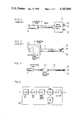
- FIG. 1 shows a conventional proximity switch of the high frequency oscillation type, in which a detector head 2 having a coil 21 contained therein and a signal detector circuit 3 are interconnected through a cable 1.
- reference numeral 31 denotes a power supply input line to the signal detector circuit and 32 is a signal line showing "ON" or "OFF" of the proximity switch.
- the signal detector circuit 3 is housed in a relatively large boxy case.
- installing the case housing the signal detector circuit 3 in the vicinity of the detector head 2 will be objectonable because of increased spatial restriction in using the proximity switch. It is for this reason that the detector head 2 and the signal detector circuit 3 are normally installed apart from each other. Consequently, the cable 1 connecting the detector head 2 and the signal detector circuit 3 needs to be long, thus tending to be affected by noise.
- This separation of the signal detector circuit 3 and the detector head 2 from each other usually requires taking the trouble of connecting the signal detector circuit 3 and detector head 2 by wiring, every time this proximity switch is to be used.
- FIG. 2 depicts a conventional proximity switch of the high frequency oscillator type which has been proposed and practically used for overcoming the above problem.
- the proximity switch in FIG. 2 is of a type having the signal detector circuit 3 provided within the detector head 2.
- Proximity switches of this type involve a disadvantage that the larger detector head is more likely to be subject to spatial restriction, although the inducement of noise and the troublesome wiring are averted.
- the high frequency oscillation type proximity switch of this invention is characterized in that a small-diameter housing case is provided in the cable connecting the detector head and the power source, a printed substrate for a signal detector circuit is provided inside the housing case and the housing case is filled with an insulating resin.
- This invention has as its object providing an proximity switch of the high frequency oscillation type which is less affected by noise.
- Another object of this invention is to provide a proximity switch of the high frequency oscillation type which does not require taking trouble of connecting by wiring the detector head and the signal detector circuit proximity
- FIG. 3 is a external view of an proximity switch of the high frequency oscillation type according to this invention.
- FIG. 4 is a partly broken perspective view of the housing case used in the proximity switch of high frequency oscillation type shown in FIG. 3,
- FIG. 5 is a block diagram schematically showing the detector circuit used in the proximity switch of high frequency oscillation type of this invention.
- FIG. 6 is a drawing illustrating another housing case employed in the proximity switch of high frequency oscillation type of this invention.
- the cable is composed of the power side cable 12 and the detector head side cable 11.
- the cable is composed of the power side cable 12 and the detector head side cable 11.
- a housing case 40 in which the printed circuit for use as the detector circuit is provided.
- the housing case 40 is so formed as to have a diameter which is, for example, less than twice the cable diameter.
- Numeral 41 designates a metal tube made of, for example, stainless steel tubing. At one end opening of the metal tube 41, a notch 42 a little wider than the diameter of the luminous part of LED 44 is formed. The terminal part of this notch 42 is of U-shape.
- Numerals 43a and 43b represent frustoconical support members integrally formed of an insulating resin.
- the bottom parts of support members 43a and 43b are so stepped as to be inserted into the openings of the metal tube 41.
- through-holes are formed in the axial direction and on the stepped part of the support member 43a, a lug 45 which is to be inserted into the notch 42 is formed, the tip of said lug having an arcuate concavity.
- Numeral 46 denotes a rectangular substrate made of ceramic. On this substrate 46, not only the signal detector circuit is formed, but LED 44 for the indication of ON-OFF operation of the proximity switch is mounted. It should be noted that the substrate should desirably be electromagnetically shielded by winding therearound a shielding plate formed by laminating a copper foil with insulating sheets on opposite surfaces thereof.
- the substrate 46 is inserted into the metal tube 41 in such a way that the luminous part of LED 44 projects out of the housing case at the terminal part of the notch 42 and the support member 43b sleeved on the cable 11 is fitted into the metal tube 41. Thereafter, in order to increase the mechanical strength of the substrate 46, an insulating resin is poured in through the one end opening of the metal tube 41. Then, by fitting the support member 43a into said opening, LED 44 is held between the bottom of the notch 42 and the tip of the lug 45 of the support member 43a. In this way, the mounting of LED 44 is facilitated. Besides, the luminous part of LED 44 projecting from the surface of the metal tube 41 to be clearly visible from any direction enables the operator to be certain of the LED's activation.
- the signal detector circuit used in this invention is described with reference to FIG. 5.
- the structure of this signal detector circuit itself is well-known.
- the signal detector circuit is composed of a high frequency oscillator circuit 4A, a detector circuit 4B, a wave form shaping circuit 4C, a comparator circuit 4D, a reference voltage circuit 4E and an output circuit 4F.
- the coil 21 is excited by the high frequency oscillator circuit 4A, so that as a result of generation of eddgy current due to approaching metal, the coil's impedance undergoes a change.
- the change in signal based on such a variation in impedance is extracted through the detector circuit 4B and the wave form shaper circuit 4C.
- the signal is inputted into the comparator circuit 4D, to be compared with the reference voltage supplied from the reference voltage circuit 4E, and the result is taken out of the output circuit 4F.
- a housing case of a cylindrical metal tube is taken as an example, but this invention is not restricted to use of such a tube.
- a V-shape notch 52 with arcuate bottom is formed and on one of the support members 53a and 53b which are fitted into the metal tube 51 is formed with a lug for engagement with the LED 54 projecting at the bottom part of the notch 52 to hold it therebetween.
- Similar effect as in the this embodiment may be achieved by installing the printed substrate for use as the signal detector circuit in such a housing case.
- this housing case may be located in proximity to the detector head. It is, therefor, possible to shorten the cable connected to the detector head, thus realizing the effect of reducing induced noise
- the housing case is preliminarily integrated with the detector head by connecting it therewith by a cable, there is no need of taking the trouble of making the connection above-mentioned when using the proximity switch.
- the proximity switch of high frequency oscillation type of this invention does not have its signal detector circuit provided in the detector head, the detector head remains small in size.
Landscapes
- Switches That Are Operated By Magnetic Or Electric Fields (AREA)
- Electronic Switches (AREA)
Applications Claiming Priority (4)
| Application Number | Priority Date | Filing Date | Title |
|---|---|---|---|
| JP8805383U JPS59193029U (ja) | 1983-06-09 | 1983-06-09 | 高周波発振型の近接スイツチ |
| JP58-088053[U] | 1983-06-09 | ||
| JP58-151789[U] | 1983-06-29 | ||
| JP15178983U JPS6069453U (ja) | 1983-09-29 | 1983-09-29 | 近接スイツチにおけるled取付け構造体 |
Publications (1)
| Publication Number | Publication Date |
|---|---|
| US4583006A true US4583006A (en) | 1986-04-15 |
Family
ID=26429493
Family Applications (1)
| Application Number | Title | Priority Date | Filing Date |
|---|---|---|---|
| US06/616,649 Expired - Lifetime US4583006A (en) | 1983-06-09 | 1984-06-04 | High frequency oscillation type proximity switch |
Country Status (3)
| Country | Link |
|---|---|
| US (1) | US4583006A (de) |
| CH (1) | CH663303A5 (de) |
| DE (1) | DE3420920A1 (de) |
Cited By (6)
| Publication number | Priority date | Publication date | Assignee | Title |
|---|---|---|---|---|
| US4667147A (en) * | 1985-04-24 | 1987-05-19 | Siemens Aktiengesellschaft | Inductive proximity switch |
| US4719362A (en) * | 1985-10-02 | 1988-01-12 | Werner Turck Gmbh & Co., Kg | Electronic proximity switch dependent upon a magnetic field |
| US4757213A (en) * | 1986-05-15 | 1988-07-12 | Werner Turch GmbH & Co. KG | Non-contact operating proximity switch |
| US5034621A (en) * | 1987-12-16 | 1991-07-23 | Eaton Corporation | Inductive proximity switch exhibiting magnetic field immunity |
| US5811893A (en) * | 1995-06-22 | 1998-09-22 | Soyck Gmbh | Proximity switch for operation in the presence of interference fields |
| US6127910A (en) * | 1998-06-05 | 2000-10-03 | Topworx, Inc. | Hermetically sealed proximity switch |
Families Citing this family (2)
| Publication number | Priority date | Publication date | Assignee | Title |
|---|---|---|---|---|
| US7061234B2 (en) * | 2002-03-12 | 2006-06-13 | Omron Corporation | Modular proximity sensor |
| DE10348980A1 (de) * | 2003-10-22 | 2005-06-16 | Festo Ag & Co. | Elektronisches Bauteil, beispielsweise Positionssensor |
Citations (3)
| Publication number | Priority date | Publication date | Assignee | Title |
|---|---|---|---|---|
| US4271763A (en) * | 1978-05-15 | 1981-06-09 | Berger Philip H | Proximity detector |
| US4378504A (en) * | 1980-03-25 | 1983-03-29 | Omron Tateisi Electronics Co. | Proximity switch |
| US4456834A (en) * | 1980-10-29 | 1984-06-26 | Square D Company | Proximity switch |
Family Cites Families (4)
| Publication number | Priority date | Publication date | Assignee | Title |
|---|---|---|---|---|
| DE6602332U (de) * | 1967-02-15 | 1969-05-22 | Kabel Metallwerke Ghh | Verstaerkermuffe |
| GB1270346A (en) * | 1970-03-05 | 1972-04-12 | Square D Co | Proximity switch |
| DE7118401U (de) * | 1971-05-11 | 1971-12-02 | Ifm Electronic Geraete Gmbh & Co Kg | Tastkopf fuer ein elektronisches beruehrungslos arbeitendes schaltgeraet |
| DE2232917C3 (de) * | 1972-07-05 | 1975-10-02 | Euchner & Co, 7022 Leinfelden | Berührungsloser Schalter |
-
1984
- 1984-06-04 CH CH2704/84A patent/CH663303A5/de not_active IP Right Cessation
- 1984-06-04 US US06/616,649 patent/US4583006A/en not_active Expired - Lifetime
- 1984-06-05 DE DE19843420920 patent/DE3420920A1/de not_active Ceased
Patent Citations (3)
| Publication number | Priority date | Publication date | Assignee | Title |
|---|---|---|---|---|
| US4271763A (en) * | 1978-05-15 | 1981-06-09 | Berger Philip H | Proximity detector |
| US4378504A (en) * | 1980-03-25 | 1983-03-29 | Omron Tateisi Electronics Co. | Proximity switch |
| US4456834A (en) * | 1980-10-29 | 1984-06-26 | Square D Company | Proximity switch |
Cited By (6)
| Publication number | Priority date | Publication date | Assignee | Title |
|---|---|---|---|---|
| US4667147A (en) * | 1985-04-24 | 1987-05-19 | Siemens Aktiengesellschaft | Inductive proximity switch |
| US4719362A (en) * | 1985-10-02 | 1988-01-12 | Werner Turck Gmbh & Co., Kg | Electronic proximity switch dependent upon a magnetic field |
| US4757213A (en) * | 1986-05-15 | 1988-07-12 | Werner Turch GmbH & Co. KG | Non-contact operating proximity switch |
| US5034621A (en) * | 1987-12-16 | 1991-07-23 | Eaton Corporation | Inductive proximity switch exhibiting magnetic field immunity |
| US5811893A (en) * | 1995-06-22 | 1998-09-22 | Soyck Gmbh | Proximity switch for operation in the presence of interference fields |
| US6127910A (en) * | 1998-06-05 | 2000-10-03 | Topworx, Inc. | Hermetically sealed proximity switch |
Also Published As
| Publication number | Publication date |
|---|---|
| CH663303A5 (de) | 1987-11-30 |
| DE3420920A1 (de) | 1985-03-21 |
Similar Documents
| Publication | Publication Date | Title |
|---|---|---|
| US4583006A (en) | High frequency oscillation type proximity switch | |
| US7145348B2 (en) | Sensor device with coated electric wire shielding | |
| US4459575A (en) | High power transformer | |
| EP0395770A2 (de) | Näherungsschalter | |
| EP1744601B1 (de) | Anordnung zum Zünden einer Entladungslampe und Herstellungsverfahren dafür | |
| US20010025596A1 (en) | Heat insulation arrangement of indicating instrument | |
| JPH08249997A (ja) | 近接センサ | |
| KR0169399B1 (ko) | 후광 장치 | |
| JP2979969B2 (ja) | 照明器具用端子台ユニットおよび照明器具 | |
| WO1997018599A1 (en) | Adjustable coupling loop | |
| KR200143241Y1 (ko) | 유전체 공진기 | |
| JP2005044753A (ja) | 無電極放電灯点灯装置 | |
| US6729775B2 (en) | Electro-optical module with a housing | |
| JP3027794U (ja) | 送受信アンテナのled取付構造 | |
| JPS6327508Y2 (de) | ||
| KR20020084453A (ko) | 표면 실장용 유전체 도파관 여기 구조 | |
| JPH0126093Y2 (de) | ||
| JPH11312446A (ja) | 近接スイッチ | |
| JPH02239575A (ja) | マイクロ波ユニットの端子接続構造 | |
| JPH05129146A (ja) | 放電灯安定器 | |
| JPS61163698A (ja) | 高圧電源装置 | |
| JPH11213737A (ja) | 放電灯器具 | |
| JPH01122533A (ja) | 近接スイッチ | |
| KR19990003714U (ko) | 보강 브라켓 | |
| JPS5984749U (ja) | 近接スイツチ |
Legal Events
| Date | Code | Title | Description |
|---|---|---|---|
| STCF | Information on status: patent grant |
Free format text: PATENTED CASE |
|
| FEPP | Fee payment procedure |
Free format text: PAYOR NUMBER ASSIGNED (ORIGINAL EVENT CODE: ASPN); ENTITY STATUS OF PATENT OWNER: LARGE ENTITY |
|
| AS | Assignment |
Owner name: KEYENCE CO., LTD., JAPAN Free format text: ASSIGNMENT OF ASSIGNORS INTEREST.;ASSIGNORS:OKADA, TOSHIO;KANZAWA, AKIRA;REEL/FRAME:005043/0882 Effective date: 19890303 |
|
| FPAY | Fee payment |
Year of fee payment: 4 |
|
| FEPP | Fee payment procedure |
Free format text: PAYER NUMBER DE-ASSIGNED (ORIGINAL EVENT CODE: RMPN); ENTITY STATUS OF PATENT OWNER: LARGE ENTITY Free format text: PAYOR NUMBER ASSIGNED (ORIGINAL EVENT CODE: ASPN); ENTITY STATUS OF PATENT OWNER: LARGE ENTITY |
|
| FPAY | Fee payment |
Year of fee payment: 8 |
|
| FPAY | Fee payment |
Year of fee payment: 12 |