US4732377A - Device for controlling guiding tongues of a product diverter - Google Patents
Device for controlling guiding tongues of a product diverter Download PDFInfo
- Publication number
- US4732377A US4732377A US07/024,381 US2438187A US4732377A US 4732377 A US4732377 A US 4732377A US 2438187 A US2438187 A US 2438187A US 4732377 A US4732377 A US 4732377A
- Authority
- US
- United States
- Prior art keywords
- rocking arm
- cam disk
- follower lever
- cam follower
- cam
- Prior art date
- Legal status (The legal status is an assumption and is not a legal conclusion. Google has not performed a legal analysis and makes no representation as to the accuracy of the status listed.)
- Expired - Fee Related
Links
Images

Classifications
-
- B—PERFORMING OPERATIONS; TRANSPORTING
- B65—CONVEYING; PACKING; STORING; HANDLING THIN OR FILAMENTARY MATERIAL
- B65H—HANDLING THIN OR FILAMENTARY MATERIAL, e.g. SHEETS, WEBS, CABLES
- B65H29/00—Delivering or advancing articles from machines; Advancing articles to or into piles
- B65H29/58—Article switches or diverters
-
- B—PERFORMING OPERATIONS; TRANSPORTING
- B65—CONVEYING; PACKING; STORING; HANDLING THIN OR FILAMENTARY MATERIAL
- B65H—HANDLING THIN OR FILAMENTARY MATERIAL, e.g. SHEETS, WEBS, CABLES
- B65H2403/00—Power transmission; Driving means
- B65H2403/50—Driving mechanisms
- B65H2403/51—Cam mechanisms
- B65H2403/512—Cam mechanisms involving radial plate cam
-
- B—PERFORMING OPERATIONS; TRANSPORTING
- B65—CONVEYING; PACKING; STORING; HANDLING THIN OR FILAMENTARY MATERIAL
- B65H—HANDLING THIN OR FILAMENTARY MATERIAL, e.g. SHEETS, WEBS, CABLES
- B65H2404/00—Parts for transporting or guiding the handled material
- B65H2404/60—Other elements in face contact with handled material
- B65H2404/63—Oscillating, pivoting around an axis parallel to face of material, e.g. diverting means
- B65H2404/632—Wedge member
Definitions
- the present invention relates to a device for operating guiding tongues of a product diverter for use, for example in polygraphic machines.
- the product diverter of this kind is designed for diverting a stream of sheets to be folded, for example, or diverting singular sheets to different paths.
- a device for sorting out defective sheets wherein a cam disk driven synchronously with a cross cutter moves via a lever system the guiding tongues of the diverter until the movements of the cam disk are inactivated by means of an electromagnetic locking mechanism.
- This known device enables the sorting of sheets having predetermined fixed characteristics but cannot selectively divide the entire stream of sheets or alternately divert selected sheets from the stream to different directions.
- DE-AS No. 25 59 138 discloses a diverter for directing flat workpieces from a conveyor belt onto two subsequent conveyor belts.
- the guiding tongues in this prior art device alternately receive driving impulses through springs activated upon the release of locking pawls or catches tensioned in reciprocating cycles by means of a crank drive of a sliding wedge mechanism which also releases the locking pawls.
- devices of this kind are suitable for dividing a stream workpieces. Nevertheless, their main disadvantage is the inability to alternate the division of the stream of the workpieces or to divert at a predetermined time point the entire stream to one or other direction.
- Another disadvantage of these known devices is a high noise level during operation.
- a synchronized locking mechanism cooperates with a pneumatic double-acting locking cylinder controlled by different signals.
- a pressure accumulator is created for an instantaneous switchover when a gap in the product stream occurs.
- This mechanism which is advantageous for a synchronized control is also unable to solve the problem of an alternating switchover at a high frequency because the relatively high inertia of the pneumatic drive and the numerous additional control members prevent such fast changes.
- Another object of this invention is to provide such an improved diverting device which is reliable in operation and inexpensive to manufacture.
- Still another object of this invention is to provide such an improved device which enables an exact division of a stream of products following rapidly one after the other at a high frequency either at a certain time or to control the division in such a manner that after a certain time point either one or the other direction is selected.
- one feature of this invention resides in a combination including the mounting of the guiding tongues on a tiltably supported shaft which is directly connected to one end of a cam follower arm which by means of a first biasing spring is urged into engagement with a cam disk, the cam disk being rotatable in a bearing and driven by a driving gear in synchronism with the machine cycles.
- the bearing of the cam disk and of the driving gear being mounted on the free end of a rocking arm whose other end is supported for rocking movement in a pivot point on the machine frame.
- the rocking arm is linked to a central portion of a rocker bar whose ends are linked to armatures of two solenoids acting in opposite directions relative to each other to move stepwise the rocking arm into different positions.
- the movement of the rocking arm is limited by an abutment on the machine frame.
- the arm is spring loaded against the abutment by a second spring which is weaker than the spring of the cam follower lever.
- a spring loaded first pawl is linked to an armature of one solenoid and cooperates with a free end portion of the rocking arm to limit is movement away from to the fixed abutment.
- a second spring-loaded pawl is linked to the other solenoid and cooperates with an abutment provided on the free end of the cam follower lever to lock the same in predetermined positions.
- the cam disk is firmly connected to an intermediate gear which meshes with a driving gear connected to a main driving shaft of the machine which is coaxial with the pivot axis of the rocking arm.
- the advantages of the solution according to the invention reside particularly in the fact that the sheet-like products or sheets supplied in a processing machine at a high feeding rate at regular time intervals can be either alternately diverted in different feeding directions or after a certain time point diverted into one of two feeding directions. It is of particular advantage that in any application it is possible to achieve an exact kinematic synchronization for the actuation of the rocker bar.
- the switchover of operating conditions is performed in concert with this synchronization and is not limited to the time period of a gap between the supplied sheets.
- the start of the switchover process can begin at a time point at which the trailing edge of the preceding sheet-shaped product has not yet reached the diverting edge of the guiding tongue when viewed in the intended new direction of transportation.
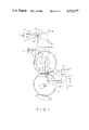
- FIG. 1 is a schematic side view of one embodiment of the device of this invention.
- FIG. 2 is a schematic side view of another embodiment.
- a series of sheet-shaped products or sheets arrive in the direction of arrow Z from a non-illustrated processing machine in a conventional manner, for example conveyed on non-illustrated conveying bands, rollers or on a transfer cylinder.
- the diverting edge of the guiding tongue 1 Depending on the position of the diverting edge of the guiding tongue 1 relative to the stream Z of conveyed products, namely whether the diverting edge is below or above the conveyed products, the latter are diverted to run either in the direction A along the guiding side 1A or in the direction B along the guiding side 1B and are conveyed in the diverted directions by conventional means.
- a plurality of guiding tongues 1 are fixed side by side on a pivot shaft 2 which is supported for rotation on a machine frame 3.
- a cam follower lever 4 is rigidly connected at one end thereof to the pivot shaft 2 and is spring-loaded by a pressure spring 5 to resiliently engage at its free a cam disk 6.
- the cam disk 6 is fixed to a side of a gear 7 and rotates jointly with the latter in a pivot bearing 8.
- the pivot bearing 8 is mounted on a free end portion of a rocking arm 9 whose other end is secured to a pivot joint 10 supported for rotation on the machine frame 3.
- the pivot joint is coaxial with the axis of rotation of the driving gear 11 meshing with the main driving gear of the machine and with the gear 7 of the cam disk 6.
- the shaft of the driving gear 11 is also supported for rotation on the machine frame and the gear 11 thus drives the cam disk 6 in synchronism with the machine cycles.
- the cam disk 6 is shaped with high and low camming surfaces whose sizes depend respectively on the time of passage of a product or sheet over the diverting edge of the guide tongue and whose ascending or descending surfaces are designed to match the gaps between the products.
- the working arm 9 which supports the cam disk 6 keeps taking such positions at which the guiding tongues 1 are oriented relative to the product stream in the directions corresponding to the selected operational mode.
- the rocking arm 9 is linked at the joint 12 with a central part of a rocker arm 13 whose ends are linked via additional joints 12' and 12" and connected rods 14' and 14 to armatures of control solenoids 15 and 16 acting in opposite directions relative one to another.
- the positions of solenoids 15 and 16 are electrically adjustable and determine the position of the free end of the rocking arm and hence the position of the cam disk 6 relative to the cam follower lever 4.
- FIG. 2 In a second embodiment of this invention illustrated in FIG. 2 the arrangement of driving members and machines elements 1 through 11 is substantially the same as in the embodiment of FIG. 1. The principal difference is in the modification of the locking arm 9 and of the cam follower lever 4 and also in the provision of electromagnetically activated locking pawls 17 and 18 for determining the selected operational modes.
- the stop pawl 17 is brought by tensioning spring 17' into a position illustrated in full line in FIG. 2 in which it locks the rocking arm against the fixed abutment 19.
- the second locking or stop pawl 18 is tilted by tensioning spring 18' into the position illustrated in full line in which it disengages the cam follower lever 4 thus permitting its free movement. Accordingly, the cam disk 6 moves the cam follower lever 4 back and forth in synchronism with the machine cycles between the positions r and s of the diverting edge of the guiding tongue 1 and the stream of products is alternately diverted in directions A and B.
- the solenoid 23 is energized. Due to the force of pressure spring 5 acting via the cam follower lever 4, the cam disk 6 and the rocking arm 9 on the first stop pawl 17, the latter can switch over from its illustrated position when the force of spring 5 is taken up by an adjustable limit stop 20 cooperating with the cam follower lever 4 in such a manner that the latter abuts against the stop in an intermediate position of the cam disk.
- the low cam surface only slightly releases the cam follower lever from the limit stop 20.
- the first stop pawl 17 releases the rocking arm 9 which springs under the action of pressure spring 21 from position t to position t'.
- the strength of pressure spring 21 is less than that of the pressure spring 5 so that the cam follower lever 4 remains on the limit stop 20 and consequently the guiding tongues 1 remain in the position s.
- the high camming surface of the cam disk 6 moves the cam follower lever 4 in a position in which the second stop pawl 18 when actuated by the second solenoid 22 can rotate against the force of spring 18' into engagement with the right-hand side of the cam follower lever. In all preceding positions, this locking engagement was prevented by the stop surface 25 formed at right angles at the free end of the cam follower lever.
- the diverting device provides both high switching frequency and well defined switching cycles accurately correlated to the feeding rate of the processed sheets in any selected operational mode.
- the embodiment of FIG. 1 shows a design in which the swinging of the cam is controlled substantially electrically whereas in the embodiment of FIG. 2 a mechanical adjustment for controlling the product diverting positions is of greater importance.
Landscapes
- Engineering & Computer Science (AREA)
- Mechanical Engineering (AREA)
- Separation, Sorting, Adjustment, Or Bending Of Sheets To Be Conveyed (AREA)
- Sheets, Magazines, And Separation Thereof (AREA)
Applications Claiming Priority (2)
| Application Number | Priority Date | Filing Date | Title |
|---|---|---|---|
| DD287715 | 1986-03-10 | ||
| DD86287715A DD246524B5 (de) | 1986-03-10 | 1986-03-10 | Vorrichtung zum betaetigen der leitzungen einer produktenweiche |
Publications (1)
| Publication Number | Publication Date |
|---|---|
| US4732377A true US4732377A (en) | 1988-03-22 |
Family
ID=5577058
Family Applications (1)
| Application Number | Title | Priority Date | Filing Date |
|---|---|---|---|
| US07/024,381 Expired - Fee Related US4732377A (en) | 1986-03-10 | 1987-03-10 | Device for controlling guiding tongues of a product diverter |
Country Status (5)
| Country | Link |
|---|---|
| US (1) | US4732377A (de) |
| DD (1) | DD246524B5 (de) |
| DE (1) | DE3704796A1 (de) |
| FR (1) | FR2595340B1 (de) |
| GB (1) | GB2187717B (de) |
Cited By (5)
| Publication number | Priority date | Publication date | Assignee | Title |
|---|---|---|---|---|
| US5022638A (en) * | 1989-04-24 | 1991-06-11 | Pitney Bowes Inc. | Envelope transporting aligning and stacking module |
| US6244593B1 (en) | 1999-08-11 | 2001-06-12 | Quad/Tech, Inc. | Sheet diverter with non-uniform drive for signature collation and method thereof |
| US6565274B1 (en) * | 2001-12-31 | 2003-05-20 | Ncr Corporation | Sheet printing and discharging apparatus |
| US20090159660A1 (en) * | 2007-12-20 | 2009-06-25 | Ncr Corporation | Document diverter apparatus for use in a check processing module of a self-service check depositing terminal |
| DE102012005598A1 (de) * | 2012-03-19 | 2013-09-19 | Weber Maschinenbau Gmbh Breidenbach | Vorrichtung zum Fördern von Produkten |
Families Citing this family (3)
| Publication number | Priority date | Publication date | Assignee | Title |
|---|---|---|---|---|
| FR2677002B1 (fr) * | 1991-05-30 | 1993-10-01 | Bertin Et Cie | Dispositif pour maintenir une piece mobile a volonte dans une premiere ou une deuxieme position, et la faire passer alternativement d'une position a l'autre. |
| US5249493A (en) * | 1992-01-21 | 1993-10-05 | Heidelberg-Harris Gmbh | Device for extracting samples from a folder |
| DE19802995C2 (de) * | 1998-01-28 | 1999-11-25 | Zirkon Druckmaschinen Gmbh | Vorrichtung zur Steuerung einer Produktweiche für Falzprodukte |
Citations (5)
| Publication number | Priority date | Publication date | Assignee | Title |
|---|---|---|---|---|
| US1107272A (en) * | 1907-07-11 | 1914-08-18 | Paul Dumesnil | Blowpipe. |
| DE1044589B (de) * | 1956-03-02 | 1958-11-20 | Licentia Gmbh | Querschneidevorrichtung mit Schnittregelung fuer Papier-, Folien- oder dergleichen Bahnen sowie einer Einrichtung zum Markieren und Aussortieren fehlerhafter Bogen |
| CH340839A (de) * | 1956-05-28 | 1959-09-15 | Mueller Hans | Verfahren zur Beschickung von mindestens zwei Papierbearbeitungsmaschinen mit Papierbogen und Einrichtung zur Durchführung des Verfahrens |
| DE2229286A1 (de) * | 1972-06-15 | 1974-04-18 | Windmoeller & Hoelscher | Betaetigungseinrichtung fuer eine am gabelungspunkt des transportweges flacher werkstuecke angeordnete weiche |
| DE2559138A1 (de) * | 1975-12-30 | 1977-07-14 | Windmoeller & Hoelscher | Weiche zur verteilung von auf einer foerdereinrichtung zugefuehrten flachen werkstuecken auf zwei weiterfoerdernde foerdereinrichtungen |
Family Cites Families (4)
| Publication number | Priority date | Publication date | Assignee | Title |
|---|---|---|---|---|
| DE2200260A1 (de) * | 1971-01-04 | 1972-08-24 | Gannicott David James Hansford | Blattstapelvorrichtung |
| GB1461554A (en) * | 1975-04-08 | 1977-01-13 | Wicks Wilson Ltd | Microfilm card duplication |
| US4518161A (en) * | 1982-01-22 | 1985-05-21 | Tokyo Shibaura Denki Kabushiki Kaisha | Sheet sorting apparatus |
| GB2176331A (en) * | 1985-06-07 | 1986-12-17 | De La Rue Syst | Cash dispensers |
-
1986
- 1986-03-10 DD DD86287715A patent/DD246524B5/de not_active IP Right Cessation
- 1986-10-08 FR FR868614001A patent/FR2595340B1/fr not_active Expired - Lifetime
-
1987
- 1987-02-16 DE DE19873704796 patent/DE3704796A1/de not_active Withdrawn
- 1987-03-05 GB GB8705125A patent/GB2187717B/en not_active Expired
- 1987-03-10 US US07/024,381 patent/US4732377A/en not_active Expired - Fee Related
Patent Citations (5)
| Publication number | Priority date | Publication date | Assignee | Title |
|---|---|---|---|---|
| US1107272A (en) * | 1907-07-11 | 1914-08-18 | Paul Dumesnil | Blowpipe. |
| DE1044589B (de) * | 1956-03-02 | 1958-11-20 | Licentia Gmbh | Querschneidevorrichtung mit Schnittregelung fuer Papier-, Folien- oder dergleichen Bahnen sowie einer Einrichtung zum Markieren und Aussortieren fehlerhafter Bogen |
| CH340839A (de) * | 1956-05-28 | 1959-09-15 | Mueller Hans | Verfahren zur Beschickung von mindestens zwei Papierbearbeitungsmaschinen mit Papierbogen und Einrichtung zur Durchführung des Verfahrens |
| DE2229286A1 (de) * | 1972-06-15 | 1974-04-18 | Windmoeller & Hoelscher | Betaetigungseinrichtung fuer eine am gabelungspunkt des transportweges flacher werkstuecke angeordnete weiche |
| DE2559138A1 (de) * | 1975-12-30 | 1977-07-14 | Windmoeller & Hoelscher | Weiche zur verteilung von auf einer foerdereinrichtung zugefuehrten flachen werkstuecken auf zwei weiterfoerdernde foerdereinrichtungen |
Cited By (5)
| Publication number | Priority date | Publication date | Assignee | Title |
|---|---|---|---|---|
| US5022638A (en) * | 1989-04-24 | 1991-06-11 | Pitney Bowes Inc. | Envelope transporting aligning and stacking module |
| US6244593B1 (en) | 1999-08-11 | 2001-06-12 | Quad/Tech, Inc. | Sheet diverter with non-uniform drive for signature collation and method thereof |
| US6565274B1 (en) * | 2001-12-31 | 2003-05-20 | Ncr Corporation | Sheet printing and discharging apparatus |
| US20090159660A1 (en) * | 2007-12-20 | 2009-06-25 | Ncr Corporation | Document diverter apparatus for use in a check processing module of a self-service check depositing terminal |
| DE102012005598A1 (de) * | 2012-03-19 | 2013-09-19 | Weber Maschinenbau Gmbh Breidenbach | Vorrichtung zum Fördern von Produkten |
Also Published As
| Publication number | Publication date |
|---|---|
| FR2595340A1 (fr) | 1987-09-11 |
| FR2595340B1 (fr) | 1990-02-23 |
| DE3704796A1 (de) | 1987-09-17 |
| GB2187717A (en) | 1987-09-16 |
| DD246524B5 (de) | 1993-10-14 |
| GB2187717B (en) | 1989-11-15 |
| GB8705125D0 (en) | 1987-04-08 |
| DD246524A1 (de) | 1987-06-10 |
Similar Documents
| Publication | Publication Date | Title |
|---|---|---|
| US7213493B2 (en) | Infeed apparatus for a sheet material article trimmer | |
| US8747000B2 (en) | Paper cutting device and a printer with a paper cutting device | |
| RU2067540C1 (ru) | Способ подачи печатных изделий к узлу для дальнейшей обработки и устройство для его осуществления | |
| JPH05246617A (ja) | バックルフォールディングマシン | |
| JPS58132497A (ja) | 枚葉紙材料を切断するための装置 | |
| PL81306B1 (de) | ||
| US5037016A (en) | Apparatus for supplying web-like material to a processing system | |
| US7384039B2 (en) | Registration apparatus for a sheet material article handler | |
| JPH0643231B2 (ja) | 紙折り機 | |
| US20110167971A1 (en) | Matched velocity transfer apparatus for a sheet material article trimmer | |
| US4674739A (en) | Sheet transfer device | |
| GB2052452A (en) | Apparatus for turning pads of paper or other flexible material during conveyance | |
| US3381794A (en) | Device for feeding stacks of books of the like to the cutting station of a machine | |
| EP0444110B1 (de) | Bogentransportvorrichtung mit greifer | |
| US4905986A (en) | Transport apparatus for flat products with individually controllable grippers | |
| US6895847B2 (en) | Three knife trimmer | |
| US3463484A (en) | Sheet gripping control mechanism for printing machines | |
| US3812948A (en) | Device for separating and conveying of articles, for example, chocolate bars | |
| US4911370A (en) | Method and apparatus for winding yarn | |
| US5230504A (en) | Document registration apparatus with adjustment for handling documents of different lengths | |
| JPH05305787A (ja) | 用紙クランプ装置 | |
| US4884675A (en) | Linking process and linking device between a fabrication machine for envelopes and a conditioning machine | |
| GB2187717A (en) | Guiding articles in different directions | |
| CA2099715C (en) | Document registration apparatus with skew adjustment | |
| GB1602872A (en) | Automatic collator unloader |
Legal Events
| Date | Code | Title | Description |
|---|---|---|---|
| AS | Assignment |
Owner name: VEB KOMBINAT POLYGRAPH WERNER LAMBERZ" LEIPZIG, 7 Free format text: ASSIGNMENT OF ASSIGNORS INTEREST.;ASSIGNORS:FENSKE, HORST;STORR, RUDOLF;REEL/FRAME:004676/0641 Effective date: 19870202 |
|
| FEPP | Fee payment procedure |
Free format text: PAYOR NUMBER ASSIGNED (ORIGINAL EVENT CODE: ASPN); ENTITY STATUS OF PATENT OWNER: LARGE ENTITY |
|
| FPAY | Fee payment |
Year of fee payment: 4 |
|
| REMI | Maintenance fee reminder mailed | ||
| LAPS | Lapse for failure to pay maintenance fees | ||
| FP | Lapsed due to failure to pay maintenance fee |
Effective date: 19960327 |
|
| STCH | Information on status: patent discontinuation |
Free format text: PATENT EXPIRED DUE TO NONPAYMENT OF MAINTENANCE FEES UNDER 37 CFR 1.362 |