US4994633A - Bend-tolerant superconductor cable - Google Patents
Bend-tolerant superconductor cable Download PDFInfo
- Publication number
- US4994633A US4994633A US07/289,226 US28922688A US4994633A US 4994633 A US4994633 A US 4994633A US 28922688 A US28922688 A US 28922688A US 4994633 A US4994633 A US 4994633A
- Authority
- US
- United States
- Prior art keywords
- superconductor
- duct
- recited
- reinforcing
- cable
- Prior art date
- Legal status (The legal status is an assumption and is not a legal conclusion. Google has not performed a legal analysis and makes no representation as to the accuracy of the status listed.)
- Expired - Fee Related
Links
Images


Classifications
-
- H—ELECTRICITY
- H01—ELECTRIC ELEMENTS
- H01F—MAGNETS; INDUCTANCES; TRANSFORMERS; SELECTION OF MATERIALS FOR THEIR MAGNETIC PROPERTIES
- H01F41/00—Apparatus or processes specially adapted for manufacturing or assembling magnets, inductances or transformers; Apparatus or processes specially adapted for manufacturing materials characterised by their magnetic properties
- H01F41/02—Apparatus or processes specially adapted for manufacturing or assembling magnets, inductances or transformers; Apparatus or processes specially adapted for manufacturing materials characterised by their magnetic properties for manufacturing cores, coils, or magnets
- H01F41/04—Apparatus or processes specially adapted for manufacturing or assembling magnets, inductances or transformers; Apparatus or processes specially adapted for manufacturing materials characterised by their magnetic properties for manufacturing cores, coils, or magnets for manufacturing coils
- H01F41/048—Superconductive coils
-
- H—ELECTRICITY
- H01—ELECTRIC ELEMENTS
- H01F—MAGNETS; INDUCTANCES; TRANSFORMERS; SELECTION OF MATERIALS FOR THEIR MAGNETIC PROPERTIES
- H01F6/00—Superconducting magnets; Superconducting coils
- H01F6/06—Coils, e.g. winding, insulating, terminating or casing arrangements therefor
-
- H—ELECTRICITY
- H10—SEMICONDUCTOR DEVICES; ELECTRIC SOLID-STATE DEVICES NOT OTHERWISE PROVIDED FOR
- H10N—ELECTRIC SOLID-STATE DEVICES NOT OTHERWISE PROVIDED FOR
- H10N60/00—Superconducting devices
- H10N60/20—Permanent superconducting devices
- H10N60/203—Permanent superconducting devices comprising high-Tc ceramic materials
-
- Y—GENERAL TAGGING OF NEW TECHNOLOGICAL DEVELOPMENTS; GENERAL TAGGING OF CROSS-SECTIONAL TECHNOLOGIES SPANNING OVER SEVERAL SECTIONS OF THE IPC; TECHNICAL SUBJECTS COVERED BY FORMER USPC CROSS-REFERENCE ART COLLECTIONS [XRACs] AND DIGESTS
- Y10—TECHNICAL SUBJECTS COVERED BY FORMER USPC
- Y10S—TECHNICAL SUBJECTS COVERED BY FORMER USPC CROSS-REFERENCE ART COLLECTIONS [XRACs] AND DIGESTS
- Y10S505/00—Superconductor technology: apparatus, material, process
- Y10S505/825—Apparatus per se, device per se, or process of making or operating same
- Y10S505/884—Conductor
- Y10S505/885—Cooling, or feeding, circulating, or distributing fluid; in superconductive apparatus
- Y10S505/886—Cable
-
- Y—GENERAL TAGGING OF NEW TECHNOLOGICAL DEVELOPMENTS; GENERAL TAGGING OF CROSS-SECTIONAL TECHNOLOGIES SPANNING OVER SEVERAL SECTIONS OF THE IPC; TECHNICAL SUBJECTS COVERED BY FORMER USPC CROSS-REFERENCE ART COLLECTIONS [XRACs] AND DIGESTS
- Y10—TECHNICAL SUBJECTS COVERED BY FORMER USPC
- Y10S—TECHNICAL SUBJECTS COVERED BY FORMER USPC CROSS-REFERENCE ART COLLECTIONS [XRACs] AND DIGESTS
- Y10S505/00—Superconductor technology: apparatus, material, process
- Y10S505/825—Apparatus per se, device per se, or process of making or operating same
- Y10S505/884—Conductor
- Y10S505/887—Conductor structure
-
- Y—GENERAL TAGGING OF NEW TECHNOLOGICAL DEVELOPMENTS; GENERAL TAGGING OF CROSS-SECTIONAL TECHNOLOGIES SPANNING OVER SEVERAL SECTIONS OF THE IPC; TECHNICAL SUBJECTS COVERED BY FORMER USPC CROSS-REFERENCE ART COLLECTIONS [XRACs] AND DIGESTS
- Y10—TECHNICAL SUBJECTS COVERED BY FORMER USPC
- Y10T—TECHNICAL SUBJECTS COVERED BY FORMER US CLASSIFICATION
- Y10T29/00—Metal working
- Y10T29/49—Method of mechanical manufacture
- Y10T29/49002—Electrical device making
- Y10T29/49014—Superconductor
Definitions
- This invention relates to electrical conductors and to methods for fabricating electrical conductors which tolerate bending without jeopardizing the physical integrity of the conductive elements therein. More particularly, the present invention relates to the manufacture of superconducting cables capable of being bent to a limited degree to fabricate electrical devices, such as coils for generating electromagnetic fields.
- the brittleness of known superconductor materials can cause difficulties when the conductors are manipulated. This is so because ceramic materials generally tolerate compressive stresses more readily than tensile stresses.
- the problem has some unique considerations when the superconductor is deposited on a metallic wire substrate. More particularly, the problem arises from the different stresses which are placed on the superconductor whenever the wire is bent.
- One object of the present invention is to produce an improved superconductor cable.
- Another object of the present invention is to provide a superconductor cable that is capable of bending in the formation of electrical coils and the like, while minimizing the tensile stresses imposed on the superconductor material thereof.
- an electric cable which is useful in forming coils and the like.
- the cable comprises a superconductor, a tubular housing for the superconductor, and a flowable filler material for securing the superconductor and the housing in a fixed longitudinal relationship.
- the cross section of the tubular housing is such as to locate the neutral plane of bending away from the superconductor to effectively keep the superconductor under compression when the cable is bent to form the coil.
- the housing forms a thin-walled, elongated channel portion and has a correspondingly elongated reinforcing portion of substantial cross section.
- the channel portion is located on a first side of the housing and is oriented on the bend to be placed in compression when the cable is bent laterally in a predetermined direction to form the coil.
- the reinforcing section is located on a second side of the housing opposite from the first side with a cross section eccentric to the cross section of the housing. In this location, the reinforcing section is oriented on the bend to be placed in tension when the cable is bent.
- the housing itself comprises an elongated duct or case which holds the superconductor and forms the channel portion of the housing.
- the duct or case has a pair of opposed sidewalls, a floor connecting corresponding ends of the sidewalls, and a laterally extending opening opposite the floor.
- An elongated lid of relatively substantial thickness is mounted in the opening of the duct or case by either bonding or crimping thereto.
- the lid substantially fills the case from the opening thereto to the neutral surface produced by lateral bending of the cable to form the coil.
- the case is comprised of soft copper, while the lid is comprised of hard copper. It is to be appreciated, however, that other materials having similar characteristics and properties could be used.
- the duct may also be made of aluminum.
- the materials used in the construction of the superconductor cable of the present invention need to be selected with several considerations in mind. Specifically, these considerations include the manufacturability of the materials and their adaptability to the operating environment. More specifically, the electrical and thermal properties, as well as the relative yield strengths of the materials need to be considered. It happens that copper (Cu) has excellent electrical and thermal properties, i.e. high conductivity, and also has a relatively high Young's Modulus of elasticity. Further, copper is solderable and easily lends itself to manufacturing techniques.
- the lid be made of hard copper and the case be made of soft copper. This is so for several reasons.
- the U-shaped case is more easily deformed if it is made of the softer material.
- the harder copper of the lid permits a crimping engagement between the case and the lid during manufacture of the cable and assumes a greater portion of the bending stresses when the cable is wound into a coil.
- the hard copper lid is located on the outside of the bend.
- the present invention also contemplates a method for fabricating an elongated superconductor structure which is bendable laterally in a predetermined direction.
- the method comprises the steps of bending an elongated copper strip into a continuous, longitudinally extending U-shaped duct and thereafter disposing in the duct a superconductor member.
- a thermally and electrically conductive flowable filler is introduced into the duct to surround the superconductor member. In its operating state, the filler will be solid and will hold the superconductor member in a fixed longitudinal relationship to the duct.
- the duct is closed with an elongated reinforcing member of relatively substantial cross section compared to that of the duct. Finally, the reinforcing member is secured to the duct in a fixed longitudinal relationship.
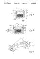
- FIG. 1 is a perspective view of a typical superconductor filament bundle
- FIG. 2 is a perspective view of one embodiment of a cable incorporating the teachings of the present invention and bent to form an electromagnetic coil;
- FIG. 3 is a cross-sectional end view of the cable as seen along the line 3--3 in FIG. 2;
- FIG. 4 is a cross-sectional end view of an alternative embodiment of a cable incorporating teachings of the present invention.
- FIG. 5 is a schematic diagram illustrating the distribution of bending-induced tensile and compressive forces within a cable according to the teachings of the present invention
- FIG. 6 is a schematic diagram illustrating a method for manufacturing an electric cable according to the teachings of the present invention.
- FIG. 7 is a sequence of cross-sectional end views of the cable in FIG. 2 during the process of the manufacture according to the method illustrated in FIG. 6.
- a typical superconductor filament 10 is manufactured by adhering to the exterior of a fibrous metallic core 12 an encasing cylindrical layer 14 of superconductor ceramic.
- Core 12 provides structural support for the otherwise brittle superconductor material in cylindrical layer 14.
- the outer surface of core 12 is oxidized prior to or during the application of cylindrical layer 14 in order to produce a barrier for protecting the superconductor material from chemical contamination by core 12.
- a coating 16 of silver may be disposed for additional protection.
- a plurality of superconductor filaments 10 are typically twisted about one another to form a superconductor filament bundle 18.
- cable 20 shown in FIG. 2 is capable of supporting any superconductor as it is bent and wound into a coil 22.
- FIG. 2 illustrates one embodiment of an electric cable 20 which incorporates the teachings of the present invention to permit the bending of the cable 20 into an electric coil 22.
- electric cable 20 comprises a superconductor member 24 and a reinforcement structure 26 which helps protect the physical integrity of the member 24 during bending in a predetermined direction.
- Superconductor member 24 comprises a plurality of superconductor filament bundles, such as bundles 18 shown in FIGS. 1 and 2, which are wound upon one another and bonded together into a substantially unitary structure.
- individual superconductor filaments 10 which are wound together to produce superconductor filament bundles 18, care must be exercised in winding bundles 18 into superconductor member 24 to insure that stresses are relatively evenly distributed among all of the components.
- reinforcement structure 26 takes the form of a tubular housing comprising an elongated duct 28 for holding superconductor member 24, an elongated lid 30, and a bonding material 32 for securing lid 30 and duct 28 in a fixed longitudinal relationship.
- Duct 28 has a pair of opposed sidewalls 34 and a floor 36 connecting corresponding ends thereof.
- Floor 36 of duct 28 defines a predetermined direction of lateral bending for electric cable 20.
- a laterally extending opening 40 that provides access into duct 28 is defined between the free ends 38 of sidewalls 34 which are remote from floor 36.
- a lid is mounted across opening 40 to enclose superconductor member 24 within duct 28.
- Lid 30 possesses a relatively larger cross section when compared to that of duct 28 and is eccentrically located relative to the overall cross section of reinforcement structure 26.
- an eccentrically located void 42 is formed within reinforcement structure 26 for housing superconductor member 24.
- lid 30 functions as an elongated reinforcing means for resisting substantially all tensile stresses imposed upon electric cable 20 by lateral bending thereof in the predetermined direction.
- the side of electric cable 20 in which superconductor member 24 is disposed is thus subjected primarily to compressive stresses during bending. These are better tolerated by superconductor materials than are tensile stresses.
- a suitable filler material 44 is utilized to secure superconductor member 24 in a longitudinally fixed relationship within reinforcement structure 26 and a bonding material 32, such as solder, may be applied to hold lid 30 in opening 40 of duct 28.
- a bonding material 32 such as solder
- the bonding material 32 may be the same as filler material 44.
- serrations 31 can be used to enhance the interlocking arrangement between lid 30 and case or duct 28.
- lid 30 is formed with serrations 31 on its surfaces which interact with free ends 38 of case 28. Because lid 30 is preferably made of harder copper than that used for case 28, a crimping of free ends 38 of case 28 onto lid 30 will drive the serrations 31 into the softer copper of case 28 to hold lid 30 on case 28.
- FIG. 4 illustrates an alternative embodiment of an electric cable 50 incorporating teachings of the present invention.
- reinforcement structure 26 comprises a duct 52, a lid 54, and bonding material 32.
- each side of lid 54 is provided with an elongated, over-hanging crimping ear 56 and adjacent thereto on the side of lid 54 opposite from superconductor member 24 a crimping recess 58.
- the sides 62 of duct 52 narrow to form a lid support shelf 64 and therebeyond free ends 60.
- crimping ears 56 rest upon lid support shelves 64, and free ends 60 are crimped or rolled from the extended position 60a thereof shown in phantom into crimping recess 58, as shown in solid. Thereafter, lid 54 and duct 52 may be further sealed by having bonding material 32 forced therebetween.
- the embodiment of the present invention, as illustrated in FIG. 4 for electric cable 50, is particularly useful in superconductor cables of substantial size, where crimping may enhance the shear strength of bonding material 32.
- reinforcement structure 26 can be appreciated as being also a tubular housing that surrounds superconductor member 24.
- the tubular housing comprises a thin-walled, elongated channel portion 70 for holding superconductor member 24 and a correspondingly elongated reinforcing portion 72 of substantial cross section eccentrically located in the cross section of the tubular housing.
- the distinct functions of channel portion 70 and reinforcing portion 72 during bending of electric cables 20 or 50 will be more easily explained in relation to FIG. 5.
- a generalized electric cable 74 incorporating teachings of the present invention is shown in FIG. 5 after having been laterally bent in a predetermined direction indicated by arrow B from its original shape 74a. As illustrated, when cable 74 is bent, the channel portion 70 of generalized electric cable 74 in which the superconductor has been placed is placed in compression. In reaction to this compression, at least part of reinforcing portion 72 thereof is placed in tension.
- neutral axis 82 in stress diagram 76 corresponds to a so-called neutral plane 84 which is the location in cable 74 where there is a change between the compressive and tensile stresses developed in generalized electric cable 74 when it is bent in the predetermined direction indicated by arrow B.
- Neutral surface 84 may, but will not necessarily, correspond to the boundary between channel portion 70 and reinforcing portion 72 of generalized electric cable 74. With proper selection of the size of the cross section of lid 30, as well as of the Young's modulus of elasticity of the material of which lid 30 and the other elements of generalized electric cable 74 are comprised, the location of neutral plane 84 in cable 74 may be varied. In any event, neutral plane 84 is preferably located in lid 30.
- an electrical cable having structure that performs three significant functions.
- the cable comprises a superconductor means, such as superconductor member 24, for conducting electricity in a substantially resistance-free manner in a longitudinal direction along the cable.
- a superconductor means such as superconductor member 24
- an elongated reinforcing means for resisting substantially all tensile stresses imposed on the cable by lateral bending thereof in a predetermined direction defined by the side of the cable in which the superconductor means is disposed.
- Such reinforcing means can take the form of lid 30 shown in FIG. 3 or lid 54 shown in FIG. 4.
- the electric cable of the present invention comprises an enclosure means for encircling the superconductor means and for securing the reinforcing means thereto in a longitudinally fixed relationship.
- a channel means comprising duct 28 is provided for holding the superconductor means.
- the channel means is secured to the reinforcing means either by a bonding material 32 alone, or in addition or in the alternative, by crimping as illustrated in the case of free ends 38 of side wall of duct 28 in FIG. 3.
- the reinforcing means e.g. lid 30, of the present invention, to shift the neutral plane of bending away from the superconductor means.
- the superconductor means will be substantially in compression.
- the present invention also contemplates a method for producing the superconductor cables described above. Such a method is illustrated schematically in FIG. 6 and correspondingly by successive cross-sectional views of the cable in its various steps of fabrication. As shown in FIG. 6, an assembly line series of processes for fabricating generalized electric cable 74 are shown in which the materials involved move from left to right in a direction indicated by arrow C.
- a roller 100 feeds an elongated thin copper strip 102 shown in cross section in step A of FIG. 7 into a series of forming rollers 104. As strip 102 passes through rollers 104, the copper strip 102 is bent into a continuous, longitudinally extending U-shaped duct 106 shown in cross section in step B of FIG. 7.
- Duct 106 has a floor 108, two parallel sidewalls 110 extending therefrom, and an opening 112 between the free ends 114 of sidewalls 110.
- a superconductor member 118 is disposed in duct 106 adjacent to floor 108 thereof as shown in step C of FIG. 7. Thereafter, a flowable filler 120 is introduced from a filler source 122 into duct 106 to surround superconductor member 118 in the portion of duct 106 adjacent to floor 108 thereof. A cross section of the evolving cable in this state of manufacture appears at step D in FIG. 7. Flowable filler 120 serves to stabilize superconductor member 118 in a fixed longitudinal relationship to duct 106.
- a third roller 124 feeds an elongated reinforcing member 126 of relatively substantial cross section into opening 112 of duct 106, where reinforcing member 126 rests upon filler 120 and superconductor member 118 as shown in step E of FIG. 7. Reinforcing member 126 thus functions as a lid for closing duct 106. Thereafter, reinforcing member 126 is secured to duct 106 either by crimping of walls 110 thereagainst, or as shown in step F of FIG. 7, by the injection between reinforcing member 126 and walls 110 of a bonding material 128, such as solder, at a soldering station 130. Thereafter, the completed electric cable 74 can be wound onto a fourth roller 132.
- the present invention has utility not merely with superconductor materials, but with any type of conductor sensitive to tensile stresses. It is further understood that the principles of the present invention disclosed herein are useful for protecting conductor materials which, unlike currently known superconductor materials, are sensitive to compression. Compression-sensitive conductors could be protected in bending by reversing the relative position of the conductor and the reinforcing means in the above-described embodiments of the invention in relation to the predetermined direction of lateral bending therefor.
- the reinforcing member or lid for the duct in which the conductor is placed would define the direction of lateral bending, so that the neutral plane during bending, by falling between the reinforcing member and the conductor, would result in tensile stresses exclusively being applied to the reinforcing member, rather than to the compression-sensitive conductor.
Landscapes
- Engineering & Computer Science (AREA)
- Power Engineering (AREA)
- Manufacturing & Machinery (AREA)
- Chemical & Material Sciences (AREA)
- Ceramic Engineering (AREA)
- Superconductors And Manufacturing Methods Therefor (AREA)
- Installation Of Indoor Wiring (AREA)
Priority Applications (4)
| Application Number | Priority Date | Filing Date | Title |
|---|---|---|---|
| US07/289,226 US4994633A (en) | 1988-12-22 | 1988-12-22 | Bend-tolerant superconductor cable |
| CA002004898A CA2004898A1 (en) | 1988-12-22 | 1989-12-07 | Bend-tolerant superconductor cable |
| EP19890313266 EP0375353A3 (de) | 1988-12-22 | 1989-12-19 | Eine Verstärkung für eine supraleitende Vorrichtung |
| JP1332530A JP2892724B2 (ja) | 1988-12-22 | 1989-12-21 | 曲げ可能の超電導体ケーブル |
Applications Claiming Priority (1)
| Application Number | Priority Date | Filing Date | Title |
|---|---|---|---|
| US07/289,226 US4994633A (en) | 1988-12-22 | 1988-12-22 | Bend-tolerant superconductor cable |
Publications (1)
| Publication Number | Publication Date |
|---|---|
| US4994633A true US4994633A (en) | 1991-02-19 |
Family
ID=23110598
Family Applications (1)
| Application Number | Title | Priority Date | Filing Date |
|---|---|---|---|
| US07/289,226 Expired - Fee Related US4994633A (en) | 1988-12-22 | 1988-12-22 | Bend-tolerant superconductor cable |
Country Status (4)
| Country | Link |
|---|---|
| US (1) | US4994633A (de) |
| EP (1) | EP0375353A3 (de) |
| JP (1) | JP2892724B2 (de) |
| CA (1) | CA2004898A1 (de) |
Cited By (28)
| Publication number | Priority date | Publication date | Assignee | Title |
|---|---|---|---|---|
| US5057489A (en) * | 1990-09-21 | 1991-10-15 | General Atomics | Multifilamentary superconducting cable with transposition |
| US5200391A (en) * | 1990-09-24 | 1993-04-06 | General Atomics | Method and apparatus for fabricating a multifilamentary wire |
| US5512867A (en) * | 1991-04-02 | 1996-04-30 | Sumitomo Electric Industries, Ltd. | High temperature superconducting coil and method of manufacturing thereof |
| WO1998009295A1 (en) * | 1996-08-30 | 1998-03-05 | American Superconductor Corporation | Laminated superconducting ceramic tape |
| US5798678A (en) * | 1994-01-28 | 1998-08-25 | American Superconductor Corporation | Superconducting wind-and-react-coils and methods of manufacture |
| EP0860030A1 (de) * | 1995-11-07 | 1998-08-26 | American Superconductor Corporation | Behandlung von oxydsupraleitenden kabeln |
| RU2122759C1 (ru) * | 1997-07-07 | 1998-11-27 | Государственный научный центр РФ Всероссийский научно-исследовательский институт неорганических материалов им.акад.А.А.Бочвара | Способ получения высокотемпературных проводников |
| RU2124773C1 (ru) * | 1997-06-10 | 1999-01-10 | Государственный научный центр РФ Всероссийский научно-исследовательский институт неорганических материалов им.акад. А.А.Бочвара | Способ получения длинномерных высокотемпературных проводников |
| RU2124772C1 (ru) * | 1997-06-10 | 1999-01-10 | Государственный научный центр Российской Федерации Всероссийский научно-исследовательский институт неорганических материалов им.акад. А.А.Бочвара | Способ получения длинномерных высокотемпературных сверхпроводящих изделий |
| RU2124775C1 (ru) * | 1997-06-10 | 1999-01-10 | Государственный научный центр Российской Федерации Всероссийский научно-исследовательский институт неорганических материалов им.акад. А.А.Бочвара | Способ получения длинномерных высокотемпературных сверхпроводящих изделий |
| RU2124774C1 (ru) * | 1997-06-10 | 1999-01-10 | Государственный научный центр Российской Федерации Всероссийский научно-исследовательский институт неорганических материалов им.акад. А.А.Бочвара | Способ получения длинномерных высокотемпературных сверхпроводящих изделий |
| US6002316A (en) * | 1998-05-13 | 1999-12-14 | The Texas A&M University System | Superconducting coil and method of stress management in a superconducting coil |
| US6284712B1 (en) | 1993-04-01 | 2001-09-04 | Alexander Otto | Processing of oxide superconductors |
| US6305069B1 (en) * | 1995-04-07 | 2001-10-23 | Sumitomo Electric Industries, Inc. | Method of preparing oxide superconductive wire |
| US6393690B1 (en) | 1995-05-19 | 2002-05-28 | American Superconductor Corpration | Structure and method of manufacture for minimizing filament coupling losses in superconducting oxide composite articles |
| US6428635B1 (en) | 1997-10-01 | 2002-08-06 | American Superconductor Corporation | Substrates for superconductors |
| US6444917B1 (en) | 1999-07-23 | 2002-09-03 | American Superconductor Corporation | Encapsulated ceramic superconductors |
| US6458223B1 (en) | 1997-10-01 | 2002-10-01 | American Superconductor Corporation | Alloy materials |
| US6475311B1 (en) | 1999-03-31 | 2002-11-05 | American Superconductor Corporation | Alloy materials |
| US6633215B2 (en) * | 2001-05-01 | 2003-10-14 | Ge Medical Systems Global Technology Company, Llc | Superconducting magnetic resonance imaging magnet assembly and method with reverse wire channel orientation |
| US6649280B1 (en) | 1996-08-30 | 2003-11-18 | American Superconductor Corporation | Cryogen protected superconducting ceramic tape |
| US6762673B1 (en) * | 1998-02-10 | 2004-07-13 | American Superconductor Corp. | Current limiting composite material |
| RU2273906C1 (ru) * | 2004-07-15 | 2006-04-10 | Российский научный центр "Курчатовский институт" | Комбинированный сверхпроводник |
| US20080121411A1 (en) * | 2004-12-01 | 2008-05-29 | Sumitomo Electric Industries, Ltd. | Superconductive Cable |
| US20090194316A1 (en) * | 2006-07-14 | 2009-08-06 | Siemens Magnet Technology Limited | Wire-in-channel superconductor |
| US20180226178A1 (en) * | 2015-08-12 | 2018-08-09 | Karlsruher Institut für Technologie | Superconducting conductor and use of the superconducting conductor |
| US10658092B2 (en) * | 2016-11-08 | 2020-05-19 | Autonetworks Technologies, Ltd. | Electric wire conductor, covered electric wire, and wiring harness |
| US20210407716A1 (en) * | 2020-06-26 | 2021-12-30 | Massachusetts Institute Of Technology | Motive systems comprising a high temperature superconductor (hts) cable |
Families Citing this family (2)
| Publication number | Priority date | Publication date | Assignee | Title |
|---|---|---|---|---|
| US5801124A (en) * | 1996-08-30 | 1998-09-01 | American Superconductor Corporation | Laminated superconducting ceramic composite conductors |
| JP4775231B2 (ja) * | 2006-11-07 | 2011-09-21 | 富士電機株式会社 | 超電導コイルの製造方法 |
Citations (18)
| Publication number | Priority date | Publication date | Assignee | Title |
|---|---|---|---|---|
| US3458842A (en) * | 1967-06-19 | 1969-07-29 | Avco Corp | Superconducting magnet having dual conductors forming the turns thereof |
| DE2440172A1 (de) * | 1974-07-11 | 1976-01-29 | Bbc Brown Boveri & Cie | Verfahren zur herstellung eines supraleiters |
| DE2602729A1 (de) * | 1975-12-15 | 1977-06-16 | Bbc Brown Boveri & Cie | Supraleiter |
| US4079187A (en) * | 1975-12-15 | 1978-03-14 | Bbc Brown Boveri & Company Limited | Superconductor |
| JPS5626673A (en) * | 1979-08-07 | 1981-03-14 | Furukawa Electric Co Ltd:The | Continuous immersion soldering method |
| JPS56141107A (en) * | 1980-04-03 | 1981-11-04 | Tokyo Shibaura Electric Co | Superconductor |
| US4327244A (en) * | 1979-02-09 | 1982-04-27 | Bbc Brown, Boveri & Company, Limited | Superconductive cable |
| US4329539A (en) * | 1975-12-03 | 1982-05-11 | The Furukawa Electric Co., Ltd. | Superconducting compound stranded cable |
| US4333228A (en) * | 1978-12-22 | 1982-06-08 | Bbc Brown, Boveri & Company, Limited | Method for producing a super-conductive coil and coil produced in accordance with this method |
| US4421946A (en) * | 1979-05-18 | 1983-12-20 | The Furukawa Electric Co., Ltd. | High current capacity superconductor |
| US4454380A (en) * | 1981-03-28 | 1984-06-12 | Kernforschungszentrum Karlsruhe Gmbh | Stabilized multifilament superconductor made of brittle, prereacted Nb3 Sn filaments in a bronze matrix |
| US4490578A (en) * | 1982-07-09 | 1984-12-25 | Hitachi Cable, Ltd. | Integrated superconductor |
| US4503602A (en) * | 1981-07-10 | 1985-03-12 | Vacuumschmelze Gmbh | Method for the manufacture of a superconducting hollow conductor |
| DE3506719A1 (de) * | 1984-02-29 | 1985-08-29 | Mitsubishi Denki K.K., Tokio/Tokyo | Supraleiter |
| US4554407A (en) * | 1983-12-23 | 1985-11-19 | La Metalli Industriale S.P.A. | Superconducting conductors having a stabilizing sheath brazed to its matrix and a process for making the same |
| US4652697A (en) * | 1983-08-15 | 1987-03-24 | Hitachi, Ltd. | Aluminum-stabilized superconducting wire |
| US4673774A (en) * | 1984-11-06 | 1987-06-16 | Mitsubishi Denki Kabushiki Kaisha | Superconductor |
| US4808488A (en) * | 1986-05-22 | 1989-02-28 | Centre Nationale De La Recherche Scientifique (Cnrs) | Hybrid superconductive wires or ribbons comprising a chevrel phase and another superconductive phase |
Family Cites Families (4)
| Publication number | Priority date | Publication date | Assignee | Title |
|---|---|---|---|---|
| JPS58197703A (ja) * | 1982-05-14 | 1983-11-17 | Hitachi Ltd | 超電導コイルの製造方法 |
| JPS61136663A (ja) * | 1984-12-07 | 1986-06-24 | Showa Electric Wire & Cable Co Ltd | 複合超電導体の製造方法 |
| JPS62283605A (ja) * | 1986-05-31 | 1987-12-09 | Mitsubishi Heavy Ind Ltd | 超電導電力貯蔵装置のコイル構造 |
| JPS63313418A (ja) * | 1987-06-15 | 1988-12-21 | Nippon Telegr & Teleph Corp <Ntt> | 超伝導線及びその製造方法 |
-
1988
- 1988-12-22 US US07/289,226 patent/US4994633A/en not_active Expired - Fee Related
-
1989
- 1989-12-07 CA CA002004898A patent/CA2004898A1/en not_active Abandoned
- 1989-12-19 EP EP19890313266 patent/EP0375353A3/de not_active Withdrawn
- 1989-12-21 JP JP1332530A patent/JP2892724B2/ja not_active Expired - Lifetime
Patent Citations (18)
| Publication number | Priority date | Publication date | Assignee | Title |
|---|---|---|---|---|
| US3458842A (en) * | 1967-06-19 | 1969-07-29 | Avco Corp | Superconducting magnet having dual conductors forming the turns thereof |
| DE2440172A1 (de) * | 1974-07-11 | 1976-01-29 | Bbc Brown Boveri & Cie | Verfahren zur herstellung eines supraleiters |
| US4329539A (en) * | 1975-12-03 | 1982-05-11 | The Furukawa Electric Co., Ltd. | Superconducting compound stranded cable |
| DE2602729A1 (de) * | 1975-12-15 | 1977-06-16 | Bbc Brown Boveri & Cie | Supraleiter |
| US4079187A (en) * | 1975-12-15 | 1978-03-14 | Bbc Brown Boveri & Company Limited | Superconductor |
| US4333228A (en) * | 1978-12-22 | 1982-06-08 | Bbc Brown, Boveri & Company, Limited | Method for producing a super-conductive coil and coil produced in accordance with this method |
| US4327244A (en) * | 1979-02-09 | 1982-04-27 | Bbc Brown, Boveri & Company, Limited | Superconductive cable |
| US4421946A (en) * | 1979-05-18 | 1983-12-20 | The Furukawa Electric Co., Ltd. | High current capacity superconductor |
| JPS5626673A (en) * | 1979-08-07 | 1981-03-14 | Furukawa Electric Co Ltd:The | Continuous immersion soldering method |
| JPS56141107A (en) * | 1980-04-03 | 1981-11-04 | Tokyo Shibaura Electric Co | Superconductor |
| US4454380A (en) * | 1981-03-28 | 1984-06-12 | Kernforschungszentrum Karlsruhe Gmbh | Stabilized multifilament superconductor made of brittle, prereacted Nb3 Sn filaments in a bronze matrix |
| US4503602A (en) * | 1981-07-10 | 1985-03-12 | Vacuumschmelze Gmbh | Method for the manufacture of a superconducting hollow conductor |
| US4490578A (en) * | 1982-07-09 | 1984-12-25 | Hitachi Cable, Ltd. | Integrated superconductor |
| US4652697A (en) * | 1983-08-15 | 1987-03-24 | Hitachi, Ltd. | Aluminum-stabilized superconducting wire |
| US4554407A (en) * | 1983-12-23 | 1985-11-19 | La Metalli Industriale S.P.A. | Superconducting conductors having a stabilizing sheath brazed to its matrix and a process for making the same |
| DE3506719A1 (de) * | 1984-02-29 | 1985-08-29 | Mitsubishi Denki K.K., Tokio/Tokyo | Supraleiter |
| US4673774A (en) * | 1984-11-06 | 1987-06-16 | Mitsubishi Denki Kabushiki Kaisha | Superconductor |
| US4808488A (en) * | 1986-05-22 | 1989-02-28 | Centre Nationale De La Recherche Scientifique (Cnrs) | Hybrid superconductive wires or ribbons comprising a chevrel phase and another superconductive phase |
Cited By (42)
| Publication number | Priority date | Publication date | Assignee | Title |
|---|---|---|---|---|
| US5057489A (en) * | 1990-09-21 | 1991-10-15 | General Atomics | Multifilamentary superconducting cable with transposition |
| US5200391A (en) * | 1990-09-24 | 1993-04-06 | General Atomics | Method and apparatus for fabricating a multifilamentary wire |
| US5512867A (en) * | 1991-04-02 | 1996-04-30 | Sumitomo Electric Industries, Ltd. | High temperature superconducting coil and method of manufacturing thereof |
| US6436876B1 (en) | 1993-04-01 | 2002-08-20 | American Superconductor Corporation | Processing of oxide superconductors |
| US6284712B1 (en) | 1993-04-01 | 2001-09-04 | Alexander Otto | Processing of oxide superconductors |
| US6603379B1 (en) | 1994-01-28 | 2003-08-05 | American Superconductor Corporation | Superconducing wind-and-react-coils and methods of manufacture |
| US5798678A (en) * | 1994-01-28 | 1998-08-25 | American Superconductor Corporation | Superconducting wind-and-react-coils and methods of manufacture |
| US6194352B1 (en) * | 1994-01-28 | 2001-02-27 | American Superconductor Corporation | Multifilament composite BSCCO oxide superconductor |
| US6305069B1 (en) * | 1995-04-07 | 2001-10-23 | Sumitomo Electric Industries, Inc. | Method of preparing oxide superconductive wire |
| US6393690B1 (en) | 1995-05-19 | 2002-05-28 | American Superconductor Corpration | Structure and method of manufacture for minimizing filament coupling losses in superconducting oxide composite articles |
| EP0860030A1 (de) * | 1995-11-07 | 1998-08-26 | American Superconductor Corporation | Behandlung von oxydsupraleitenden kabeln |
| US5987342A (en) * | 1996-08-30 | 1999-11-16 | American Superconductor Corporation | Laminated superconducting ceramic tape |
| US6230033B1 (en) | 1996-08-30 | 2001-05-08 | American Superconductor Corporation | Laminated superconducting ceramic tape |
| US6649280B1 (en) | 1996-08-30 | 2003-11-18 | American Superconductor Corporation | Cryogen protected superconducting ceramic tape |
| WO1998009295A1 (en) * | 1996-08-30 | 1998-03-05 | American Superconductor Corporation | Laminated superconducting ceramic tape |
| RU2124774C1 (ru) * | 1997-06-10 | 1999-01-10 | Государственный научный центр Российской Федерации Всероссийский научно-исследовательский институт неорганических материалов им.акад. А.А.Бочвара | Способ получения длинномерных высокотемпературных сверхпроводящих изделий |
| RU2124775C1 (ru) * | 1997-06-10 | 1999-01-10 | Государственный научный центр Российской Федерации Всероссийский научно-исследовательский институт неорганических материалов им.акад. А.А.Бочвара | Способ получения длинномерных высокотемпературных сверхпроводящих изделий |
| RU2124772C1 (ru) * | 1997-06-10 | 1999-01-10 | Государственный научный центр Российской Федерации Всероссийский научно-исследовательский институт неорганических материалов им.акад. А.А.Бочвара | Способ получения длинномерных высокотемпературных сверхпроводящих изделий |
| RU2124773C1 (ru) * | 1997-06-10 | 1999-01-10 | Государственный научный центр РФ Всероссийский научно-исследовательский институт неорганических материалов им.акад. А.А.Бочвара | Способ получения длинномерных высокотемпературных проводников |
| RU2122759C1 (ru) * | 1997-07-07 | 1998-11-27 | Государственный научный центр РФ Всероссийский научно-исследовательский институт неорганических материалов им.акад.А.А.Бочвара | Способ получения высокотемпературных проводников |
| US6428635B1 (en) | 1997-10-01 | 2002-08-06 | American Superconductor Corporation | Substrates for superconductors |
| US6458223B1 (en) | 1997-10-01 | 2002-10-01 | American Superconductor Corporation | Alloy materials |
| US6762673B1 (en) * | 1998-02-10 | 2004-07-13 | American Superconductor Corp. | Current limiting composite material |
| US6002316A (en) * | 1998-05-13 | 1999-12-14 | The Texas A&M University System | Superconducting coil and method of stress management in a superconducting coil |
| US6475311B1 (en) | 1999-03-31 | 2002-11-05 | American Superconductor Corporation | Alloy materials |
| US6444917B1 (en) | 1999-07-23 | 2002-09-03 | American Superconductor Corporation | Encapsulated ceramic superconductors |
| US6784362B1 (en) | 1999-07-23 | 2004-08-31 | American Superconductor Corporation | Polymer encapsulated ceramic superconductors |
| US6633215B2 (en) * | 2001-05-01 | 2003-10-14 | Ge Medical Systems Global Technology Company, Llc | Superconducting magnetic resonance imaging magnet assembly and method with reverse wire channel orientation |
| RU2273906C1 (ru) * | 2004-07-15 | 2006-04-10 | Российский научный центр "Курчатовский институт" | Комбинированный сверхпроводник |
| US20080121411A1 (en) * | 2004-12-01 | 2008-05-29 | Sumitomo Electric Industries, Ltd. | Superconductive Cable |
| RU2367044C2 (ru) * | 2004-12-01 | 2009-09-10 | Сумитомо Электрик Индастриз, Лтд. | Сверхпроводящий кабель |
| US8039742B2 (en) | 2004-12-01 | 2011-10-18 | Sumitomo Electric Industries, Ltd. | Superconductive cable |
| US20090194316A1 (en) * | 2006-07-14 | 2009-08-06 | Siemens Magnet Technology Limited | Wire-in-channel superconductor |
| US8319105B2 (en) * | 2006-07-14 | 2012-11-27 | Siemens Plc | Wire-in-channel superconductor |
| US20180226178A1 (en) * | 2015-08-12 | 2018-08-09 | Karlsruher Institut für Technologie | Superconducting conductor and use of the superconducting conductor |
| US10825585B2 (en) * | 2015-08-12 | 2020-11-03 | Karlsruher Institut für Technologie | Superconducting conductor and use of the superconducting conductor |
| US10658092B2 (en) * | 2016-11-08 | 2020-05-19 | Autonetworks Technologies, Ltd. | Electric wire conductor, covered electric wire, and wiring harness |
| US20200234846A1 (en) * | 2016-11-08 | 2020-07-23 | Autonetworks Technologies, Ltd. | Electric wire conductor, covered electric wire, and wiring harness |
| US10964446B2 (en) * | 2016-11-08 | 2021-03-30 | Autonetworks Technologies, Ltd. | Electric wire conductor, covered electric wire, and wiring harness |
| US11107602B2 (en) | 2016-11-08 | 2021-08-31 | Autonetworks Technologies, Ltd. | Electric wire conductor, covered electric wire, and wiring harness |
| US11545279B2 (en) | 2016-11-08 | 2023-01-03 | Autonetworks Technologies, Ltd. | Electric wire conductor, covered electric wire, and wiring harness |
| US20210407716A1 (en) * | 2020-06-26 | 2021-12-30 | Massachusetts Institute Of Technology | Motive systems comprising a high temperature superconductor (hts) cable |
Also Published As
| Publication number | Publication date |
|---|---|
| CA2004898A1 (en) | 1990-06-22 |
| EP0375353A2 (de) | 1990-06-27 |
| JP2892724B2 (ja) | 1999-05-17 |
| EP0375353A3 (de) | 1991-08-21 |
| JPH02270219A (ja) | 1990-11-05 |
Similar Documents
| Publication | Publication Date | Title |
|---|---|---|
| US4994633A (en) | Bend-tolerant superconductor cable | |
| US7279639B2 (en) | Superconducting cable joint structure | |
| US7166804B2 (en) | Terminal structure of superconducting cable and superconducting cable line therewith | |
| US5463186A (en) | Round electrical cable | |
| CN102918714B (zh) | 超导电缆导体的末端结构及其中所使用的端子构件 | |
| EP0155184B1 (de) | Biegsamer langgezogener Körper | |
| US7067739B2 (en) | Joint structure of superconducting cable and insulating spacer for connecting superconducting cable | |
| US5057489A (en) | Multifilamentary superconducting cable with transposition | |
| JP4213290B2 (ja) | 安定化複合超電導線材の製造方法 | |
| JP4597516B2 (ja) | フレキシブル電気配線 | |
| JPH03205706A (ja) | 適応性のある大電流導体 | |
| WO1996041352A1 (en) | Electric conductors and cables | |
| JPS63170809A (ja) | ケーブル又は導体中に配設した絶縁材の展性外被を有する高可撓性ケーブル又は電気導体及びその製造方法 | |
| JP3877057B2 (ja) | 高温超電導ケーブル | |
| JP7810034B2 (ja) | 平型電線及び端子付き平型電線 | |
| JP3549295B2 (ja) | 超電導ケーブル | |
| JP2006114342A (ja) | 超電導ケーブル | |
| JP4087469B2 (ja) | 超電導装置 | |
| US5050958A (en) | Optical fibre cable | |
| JPS5923402B2 (ja) | 超電導線材 | |
| JP3851739B2 (ja) | 超電導導体、超電導導体接続構造およびそれらを用いた超電導コイル | |
| JP4275262B2 (ja) | 超電導コイル | |
| JPS6348147B2 (de) | ||
| Petrovich et al. | Critical current of multifilamentary Nb 3 Sn-insert coil and long sample bend tests | |
| JPH10162663A (ja) | アルミ安定化超電導導体 |
Legal Events
| Date | Code | Title | Description |
|---|---|---|---|
| AS | Assignment |
Owner name: GENERAL ATOMICS, A CORP. OF CA, CALIFORNIA Free format text: ASSIGNMENT OF ASSIGNORS INTEREST.;ASSIGNOR:PUHN, FREDERICK A.;REEL/FRAME:005019/0520 Effective date: 19881222 |
|
| FEPP | Fee payment procedure |
Free format text: PAYOR NUMBER ASSIGNED (ORIGINAL EVENT CODE: ASPN); ENTITY STATUS OF PATENT OWNER: LARGE ENTITY |
|
| FPAY | Fee payment |
Year of fee payment: 4 |
|
| AS | Assignment |
Owner name: SHIMABUN CO., LTD., JAPAN Free format text: ASSIGNMENT OF ASSIGNORS INTEREST;ASSIGNOR:GENERAL ATOMICS;REEL/FRAME:007205/0642 Effective date: 19941111 |
|
| FPAY | Fee payment |
Year of fee payment: 8 |
|
| REMI | Maintenance fee reminder mailed | ||
| LAPS | Lapse for failure to pay maintenance fees | ||
| FP | Lapsed due to failure to pay maintenance fee |
Effective date: 20030219 |
|
| STCH | Information on status: patent discontinuation |
Free format text: PATENT EXPIRED DUE TO NONPAYMENT OF MAINTENANCE FEES UNDER 37 CFR 1.362 |