US5050007A - Image-scanning apparatus and method therefor - Google Patents
Image-scanning apparatus and method therefor Download PDFInfo
- Publication number
- US5050007A US5050007A US07/375,594 US37559489A US5050007A US 5050007 A US5050007 A US 5050007A US 37559489 A US37559489 A US 37559489A US 5050007 A US5050007 A US 5050007A
- Authority
- US
- United States
- Prior art keywords
- image
- documents
- image data
- data
- document
- Prior art date
- Legal status (The legal status is an assumption and is not a legal conclusion. Google has not performed a legal analysis and makes no representation as to the accuracy of the status listed.)
- Expired - Fee Related
Links
- 238000000034 method Methods 0.000 title claims description 31
- 238000012545 processing Methods 0.000 claims abstract description 16
- 230000001678 irradiating effect Effects 0.000 claims abstract 18
- 230000008859 change Effects 0.000 claims description 2
- 238000009432 framing Methods 0.000 claims 4
- 230000007246 mechanism Effects 0.000 abstract description 10
- 230000008569 process Effects 0.000 description 8
- 238000012937 correction Methods 0.000 description 6
- 238000005259 measurement Methods 0.000 description 6
- 230000000875 corresponding effect Effects 0.000 description 4
- 238000003705 background correction Methods 0.000 description 3
- 238000010586 diagram Methods 0.000 description 3
- 230000002596 correlated effect Effects 0.000 description 2
- 230000003287 optical effect Effects 0.000 description 2
- 239000004925 Acrylic resin Substances 0.000 description 1
- 229920000178 Acrylic resin Polymers 0.000 description 1
- 239000002390 adhesive tape Substances 0.000 description 1
- 230000002411 adverse Effects 0.000 description 1
- 238000003780 insertion Methods 0.000 description 1
- 230000037431 insertion Effects 0.000 description 1
- 229920003229 poly(methyl methacrylate) Polymers 0.000 description 1
- 239000004926 polymethyl methacrylate Substances 0.000 description 1
- 239000000725 suspension Substances 0.000 description 1
- 239000012780 transparent material Substances 0.000 description 1
- 230000032258 transport Effects 0.000 description 1
- 230000000007 visual effect Effects 0.000 description 1
Images


Classifications
-
- H—ELECTRICITY
- H04—ELECTRIC COMMUNICATION TECHNIQUE
- H04N—PICTORIAL COMMUNICATION, e.g. TELEVISION
- H04N1/00—Scanning, transmission or reproduction of documents or the like, e.g. facsimile transmission; Details thereof
- H04N1/00567—Handling of original or reproduction media, e.g. cutting, separating, stacking
- H04N1/0062—Removing sheets from a stack or inputting media
-
- H—ELECTRICITY
- H04—ELECTRIC COMMUNICATION TECHNIQUE
- H04N—PICTORIAL COMMUNICATION, e.g. TELEVISION
- H04N1/00—Scanning, transmission or reproduction of documents or the like, e.g. facsimile transmission; Details thereof
- H04N1/0035—User-machine interface; Control console
-
- H—ELECTRICITY
- H04—ELECTRIC COMMUNICATION TECHNIQUE
- H04N—PICTORIAL COMMUNICATION, e.g. TELEVISION
- H04N1/00—Scanning, transmission or reproduction of documents or the like, e.g. facsimile transmission; Details thereof
- H04N1/0035—User-machine interface; Control console
- H04N1/00405—Output means
- H04N1/00408—Display of information to the user, e.g. menus
- H04N1/00411—Display of information to the user, e.g. menus the display also being used for user input, e.g. touch screen
-
- H—ELECTRICITY
- H04—ELECTRIC COMMUNICATION TECHNIQUE
- H04N—PICTORIAL COMMUNICATION, e.g. TELEVISION
- H04N1/00—Scanning, transmission or reproduction of documents or the like, e.g. facsimile transmission; Details thereof
- H04N1/00567—Handling of original or reproduction media, e.g. cutting, separating, stacking
-
- H—ELECTRICITY
- H04—ELECTRIC COMMUNICATION TECHNIQUE
- H04N—PICTORIAL COMMUNICATION, e.g. TELEVISION
- H04N1/00—Scanning, transmission or reproduction of documents or the like, e.g. facsimile transmission; Details thereof
- H04N1/387—Composing, repositioning or otherwise geometrically modifying originals
- H04N1/3877—Image rotation
-
- H—ELECTRICITY
- H04—ELECTRIC COMMUNICATION TECHNIQUE
- H04N—PICTORIAL COMMUNICATION, e.g. TELEVISION
- H04N1/00—Scanning, transmission or reproduction of documents or the like, e.g. facsimile transmission; Details thereof
- H04N1/387—Composing, repositioning or otherwise geometrically modifying originals
- H04N1/393—Enlarging or reducing
Definitions
- the present invention relates to an image-scanning apparatus and image-scanning method therefor for multi-color photomechanical color printing, and more particularly, to an image-scanning apparatus and an image-scanning method therefor which require a simple operation for accurate image-scanning.
- An original is fixed on a scanner drum (transparent cylinder) by means of an adhesive tape. After that, the drum is rotated and the original is read by the sensor.
- a scanner drum transparent cylinder
- the layout sheet in this case, means the one on which a frame is precisely drawn based on an instruction paper which is given to the photomechanical process for instructing the finished size and layout.
- a layout sheet mentioned hereinafter includes not only a layout sheet itself but also an original instruction sheet and a copy thereof.
- the magnification obtained in the aforesaid way is set from the operation portion for the drum scanner.
- the original When it is necessary to fix an original according to the angle instructed by the layout sheet, the original is positioned relative to the corresponding frame on the layout sheet and an angle formed between the reference line o the layout sheet and one side of the original is measured by the use of a protractor. Or, data of an angle is obtained from a magnification measuring instrument.
- the original When fixing an original on a drum, the original is to be positioned so that an angle formed by a reference line on the drum and a reference side of the original may be the same as the measured angle. Or, the original is to be fixed on the drum after aligning the reference side of the original to the reference line of the measured angle drawn on a transparent sheet.
- An operator first determines, through the visual check, the highlight portion on the original fixed on the drum, then he turns the drum by hand so that a reading head may coincide with the determined highlight portion, and he measures the density thereof. At the same time, he measures the density on each of a shadow portion and a medium gradation point in the same manner.
- the relation between the magnification/angle thus obtained and the original is based on the memory of an operator.
- the drum In order to increase the speed for reading an original, the drum needs to be rotated at high speed, which causes an apparatus to be large in size.
- the original needs to be handled by another apparatus for the measurement of magnification, which increases the risk, of damaging the original. Further, because the originals are handled without being covered, the distinction among plural originals is difficult.
- each original requires its own magnification. In that case, there is no way but to rely upon the memory of an operator when ascertaining which measured magnification corresponds to which original, which has increased the probability of an error.
- Angle setting is done on a transparent cylinder, but it is difficult to measure an angle on the cylindrical surface, which tends to lower accuracy of measurement.
- the method employing a transparent sheet is time-consuming and there is a fear that the reading accuracy is adversely affected by the insertion of a sheet.
- the invention has been devised in view of the problems mentioned above, and its object is to realize an image scanning apparatus and method therefor wherein a magnification and an angle may be measured and set through a simple operation, thereby, a plurality of originals can be scanned efficiently.
- An image scanning apparatus of the invention that solves aforesaid problems is characterized in that the image scanning apparatus is provided with an original-holding means capable of changing an original-holding angle for original reading an original-image-reading means capable of changing the magnification for reading originals, an image-storing means capable of storing an original image read by the original-image-reading means, a display means capable of displaying images stored in the image-storing means and an instruction means that instructs the original-holding angle for aforesaid original-holding means and the reading magnification for original reading done by aforesaid original-image-reading means.
- An image scanning method that solves aforesaid problems is characterized in that the image scanning method comprises a step wherein an original held in an original-holding means capable of changing the original-holding angle is read by an original-image-reading means at a predetermined magnification and is displayed by a display means, a step wherein an instruction means instructs an angle and a magnification for the main scanning direction for reading the original image displayed by a display means, and a step wherein an original-holding angle for an original-holding means and an original-reading magnification for an original-reading means are set based on the angle and the magnification instructed by the instruction means, and original images are read again.
- the instruction for reading angle or reading magnification is inputted in the state that images are displayed by a display means after they have been read. After the completion of the input of these instructions, an angle of the original and a reading magnification are adjusted according to the instructions, and then the image scanning is carried out.
- FIG. 1 is a block diagram showing an electrical constitution of an example of the invention.
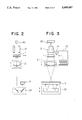
- FIGS. 2 and 3 represent a sectional view showing a mechanical constitution of embodiments of the invention.
- FIG. 4 is a flow chart showing actions of the means of an embodiment of the invention.
- FIG. 5 is a block diagram showing the constitution of a cassette.
- FIG. 6 is a perspective view showing the structure of a primary portion of a stacker and a stacker-driving mechanism.
- FIGS. 7-9 represent an illustration of a display on a CRT screen appearing for the period of image scanning.
- FIG. 1 is a block diagram showing an electrical constitution of the invention.
- 1 is a cassette wherein originals are loaded
- 2 is a lens for forming an image of an original on a line sensor
- 3 is a line sensor that converts an optical image into electrical signals.
- line sensor 3 a combination of plural line sensors and filters (or dichroic mirrors) is used.
- a device of quick switchover between an individual line sensor and a filter, or a line sensor having therein a built-in filter may also be used.
- the numeral 4 is a signal processing circuit that converts an output from a line sensor 3 into an image signal and performs signal processing such as shading correction and zero level correction
- 5 is an image processing circuit that performs image processing necessary for photomechanical process such as color correction (R, G, B ⁇ Ye, M, K, Cy), contrast transform and edge enhancement
- 6 is No. 1 image memory in which data produced after the aforesaid image processing are stored
- 7 is No.
- 8 is a digitizer in a flat shape on which the position designation concerning image processing on a computer is conducted by the use of a pointing device
- 9 is a display memory that stores data for display
- 10 is a display portion where the data stored in display memory 9 are displayed
- 11 is a control portion that controls a total apparatus entirely
- 12 is a data memory that stores, based on an instruction from control portion 11, the data concerning an original
- 13 is a mechanism control section that controls lens and others necessary to be driven mechanically
- 14 is a mechanism driving section that drives lens or the like
- 15 is an original stand that holds cassette 1 and turns and transports an original.
- FIGS. 2 and 3 represent a sectional view showing a mechanical constitution of the invention.
- 20 is a light source that illuminates an original
- 21 is a converging unit that converges light from light source
- 22 is a V-mirror unit that guides the transmitted light from an original to line sensor 3
- 23 is a stacker wherein plural cassettes are loaded and each of them is delivered one after another
- 24 is a recognizing portion where the number given to each cassette in advance is recognized when that cassette 1 is taken out of stacker 23.
- FIG. 4 represents a flow chart showing actions of the invention.
- This cassette is set on stacker 23 ⁇ step (1) ⁇ .
- the cassette has its own recognition number such as a bar code allocated in advance, thus, it is possible to recognize plural cassettes (originals).
- step (2) ⁇ prescanning among an initial menu on a CRT screen of display portion is selected ⁇ step (2) ⁇ .
- the first cassette 1 (1 ⁇ I ⁇ N) is motor-driven and fed into original stand 15 (not shown in FIG. 3) of an apparatus from stacker 23, during the period of which the recognition number of the cassette is read by recognizing portion 24.
- FIG. 6 is a perspective view showing the key portions of both stacker 23 containing cassette 1 and a driving mechanism for the stacker.
- Stacker 23 is mounted on a stacker stand which is driven by a motor, and the height of the stacker stand can be adjusted so that a necessary cassette may be taken out.
- the cassette is pushed out of the rear side of the stacker by means of a push-out mechanism (not shown in the figure) to be fed to original stand 15.
- cassette 1 is held on original stand 15 ⁇ step (4) ⁇ .
- the original stand 15 is equipped with a conveyance device that conveys a cassette toward a constant direction in a plane including an original surface.
- cassette 1 on original stand 15 is conveyed and images on the original are read by line sensor 3 ⁇ prescan: step (5) ⁇ .
- line sensor 3 ⁇ prescan: step (5) ⁇ .
- an original is a transparent one such as a positive film
- transmitted light from light source 1 is used as shown in FIG. 2.
- an original is a reflection type one such as a color print
- light is directed on the original from the side of a lens.
- a reflection mirror and light converging unit 21 are incorporated in light source 1.
- Image data obtained from the original through line sensor 3 are subjected to shading correction and zero level correction in signal processing circuit 4 and then are stored in No. 1 image memory 6. Further, the image data are stored in display memory 9 and displayed on CRT of display portion 10 (step (6)). This is shown in FIG. 7.
- the layout sheet on which a layout of photomechanical process is described is fixed on digitizer 8, and a frame covering an image area is designated by the use of a pointing device (step (7)). If the frame is rectangular, three points are designated and if it is a polygon other than a rectangle, locations corresponding, in quantity, to the number of vertexes of the polygon are designated. Thereby, information of frame size to cover images and of an angle are read and then are displayed on CRT ⁇ step (8) ⁇ .
- a cursor on a CRT screen linked with a pointing device points out two points in an image region (points A and B in FIG. 7) and other two points on a frame line (points a and b in FIG. 7), thus, for the direction of an image to be inputted within the frame on the CRT screen, A and B are caused to correspond to a and b respectively.
- a and B are caused to correspond to a and b respectively.
- designating paper used generally by a designer for instructing the layout for a photomechanical process by drawing illustrations and characters on a full-scale paper equal to a plate in size is placed on a digitizer which is a position-inputting device in a flat shape, and on the CRT screen, on the other hand, only images which have been pre-scanned and are to be inputted are outputted to be formed. Then, two points which are convenient for designating positions within the pattern of the images formed on the designating paper on the digitizer as stated above are selected, and those positions are inputted by means of a pointing device.
- FIG. 8 represents an illustration showing a display example on the CRT screen where the points of highest and lowest light intensity are determined.
- a read image At the top on the left side of the screen, there is displayed a read image.
- an original density for each of yellow Ye, magenta M and cyan C is indicated.
- "dot percentage" of each color is instructed by a scale and a cursor located at the lower portion of the screen so that it may be inputted. Also for the shadow point, the "dot percentage" therefor is inputted in the same way.
- the "dot percentage" thus obtained is stored in data memory 12 together with a recognition number of a cassette.
- the density obtained through pre-scanning is correlated with the "dot percentage”.
- a method other than the above may also be used.
- FIG. 9 represents an illustration showing a display example on the CRT screen where the contrast curve of the image is instructed.
- five types of contrast curves are shown as a basic form, and any one of them can be selected, and the selected contrast curve can further be modified by means of a cursor operation. Further, it is possible to determine the characteristic by pointing intermediate points (one or plural points).
- the contrast curve thus obtained may be stored in data memory 12 together with a recognition number of the cassette.
- image data stored in No. 1 image memory may be processed by image processing circuit 5 to be stored in No. 2 image memory, and they may further be displayed on display portion 10 through display memory 9.
- No. 1 cassette is fed by motor-powered mechanism from the stacker 23 onto original stand 15 of the apparatus.
- the recognition number of the cassette is read by recognizing portion 24.
- the cassette is held on the original stand 15 ⁇ step (17) ⁇ .
- the original stand 15 is equipped with a device capable of rotating the cassette around the axis perpendicular to the original face.
- mechanism control section 13 reads out data such as an angle and magnification stored in data memory 12, based on the recognition number of the cassette. Based on the data of angle read out, the mechanism driving section 14 rotates original stand 15. Concurrently with that, positions of both lens 2 and V-mirror unit 22 are adjusted according to the data of magnification so that an optical image may be formed on the line sensor 3 in a preferred size ⁇ step (18) ⁇ .
- the cassette 1 on the original stand 15 is transported and images on the original are read by line sensor 3 ⁇ regular scanning: step (19) ⁇ .
- the image data read out by line sensor 3 are subjected to the correction such as shading correction and zero level correction performed by signal processing circuit 4, and to the image processing necessary for photomechanical process such as color correction, contrast transform and edge enhancement performed by image processing circuit 5; and then the image data are outputted as the data of photomechanical process.
- the original stand 15 is returned to its initial state and then the cassette is returned to the stacker 23 ⁇ step (20) ⁇ .
- Aforesaid regular scanning is repeated in succession for all cassettes totaling N pieces.
- data of angle and magnification stored in data memory 12 in accordance with the recognition number of each cassette are read out, and based upon such data read out image inputting is carried out.
- it may be devised so that a part of or whole conditions may be changed in regular scanning. By doing this, it is possible to comply with a special photomechanical process.
- each original is correlated with its input conditions as stated above, and thereby it is not necessary to rely upon the memory of an operator and an extremely simple operation is realized.
- pre-scanning is followed directly by regular scanning for one cassette and the same can be repeated for the next cassette and thereafter. In this way, the total time required for scanning may be shortened.
- regular scanning is carried out after the pre-scanning for all the cassettes, an operator will not be bothered in regular scanning. Therefore, it is preferable to select based on the actual situation in the job site.
- prescanning is carried out with a fixed magnification and a fixed angle.
- prescanning is carried out with variable magnification and angle for keeping them as data, and to cause the magnification and angle for the regular scanning to be the ones correlative with those for prescanning.
- prescanning is carried out after its conditions for reading an original are set, and then the image-scanning in accordance with the aforesaid reading conditions is carried out in regular scanning.
Landscapes
- Engineering & Computer Science (AREA)
- Multimedia (AREA)
- Signal Processing (AREA)
- Human Computer Interaction (AREA)
- Facsimile Scanning Arrangements (AREA)
- Editing Of Facsimile Originals (AREA)
- Dot-Matrix Printers And Others (AREA)
- Image Input (AREA)
Applications Claiming Priority (2)
| Application Number | Priority Date | Filing Date | Title |
|---|---|---|---|
| JP63170271A JP2859617B2 (ja) | 1988-07-08 | 1988-07-08 | 画像入力方法 |
| JP63-170271 | 1988-07-08 |
Publications (1)
| Publication Number | Publication Date |
|---|---|
| US5050007A true US5050007A (en) | 1991-09-17 |
Family
ID=15901844
Family Applications (1)
| Application Number | Title | Priority Date | Filing Date |
|---|---|---|---|
| US07/375,594 Expired - Fee Related US5050007A (en) | 1988-07-08 | 1989-07-05 | Image-scanning apparatus and method therefor |
Country Status (2)
| Country | Link |
|---|---|
| US (1) | US5050007A (ja) |
| JP (1) | JP2859617B2 (ja) |
Cited By (7)
| Publication number | Priority date | Publication date | Assignee | Title |
|---|---|---|---|---|
| US5414532A (en) * | 1993-04-15 | 1995-05-09 | Dainippon Screen Mfg. Co., Ltd. | Method of prescribing processing conditions for cassette stored images and apparatus for reading images processed according to those conditions |
| US5720406A (en) * | 1993-09-10 | 1998-02-24 | Roche Diagnostic Systems, Inc. | Reaction container arrangement for use in a thermal cycler |
| US5845019A (en) * | 1992-08-20 | 1998-12-01 | Nikon Corporation | Image reader |
| US5893124A (en) * | 1992-12-03 | 1999-04-06 | Kabushiki Kaisha Toshiba | Job processing apparatus and method for preparing an instruction sheet having a predetermined format and for executing an instruction included on the instruction sheet |
| EP1023688A4 (en) * | 1996-07-23 | 2001-11-21 | R2 Technology Inc | USER INTERFACE FOR COMPUTER-AIDED DIAGNOSTIC SYSTEM |
| EP1239659A1 (de) * | 2001-03-06 | 2002-09-11 | Imip Llc | Verfahren und Vorrichtung zur digitalen Herstellung eines Bilds |
| US6532077B1 (en) * | 1995-10-04 | 2003-03-11 | Canon Kabushiki Kaisha | Image processing system |
Citations (1)
| Publication number | Priority date | Publication date | Assignee | Title |
|---|---|---|---|---|
| US4908874A (en) * | 1980-04-11 | 1990-03-13 | Ampex Corporation | System for spatially transforming images |
Family Cites Families (1)
| Publication number | Priority date | Publication date | Assignee | Title |
|---|---|---|---|---|
| JPS61265963A (ja) * | 1985-05-21 | 1986-11-25 | Dainippon Screen Mfg Co Ltd | レイアウトスキヤナにおける画像のレイアウト方法 |
-
1988
- 1988-07-08 JP JP63170271A patent/JP2859617B2/ja not_active Expired - Lifetime
-
1989
- 1989-07-05 US US07/375,594 patent/US5050007A/en not_active Expired - Fee Related
Patent Citations (1)
| Publication number | Priority date | Publication date | Assignee | Title |
|---|---|---|---|---|
| US4908874A (en) * | 1980-04-11 | 1990-03-13 | Ampex Corporation | System for spatially transforming images |
Cited By (8)
| Publication number | Priority date | Publication date | Assignee | Title |
|---|---|---|---|---|
| US5845019A (en) * | 1992-08-20 | 1998-12-01 | Nikon Corporation | Image reader |
| US5893124A (en) * | 1992-12-03 | 1999-04-06 | Kabushiki Kaisha Toshiba | Job processing apparatus and method for preparing an instruction sheet having a predetermined format and for executing an instruction included on the instruction sheet |
| US5414532A (en) * | 1993-04-15 | 1995-05-09 | Dainippon Screen Mfg. Co., Ltd. | Method of prescribing processing conditions for cassette stored images and apparatus for reading images processed according to those conditions |
| US5720406A (en) * | 1993-09-10 | 1998-02-24 | Roche Diagnostic Systems, Inc. | Reaction container arrangement for use in a thermal cycler |
| US6532077B1 (en) * | 1995-10-04 | 2003-03-11 | Canon Kabushiki Kaisha | Image processing system |
| EP1023688A4 (en) * | 1996-07-23 | 2001-11-21 | R2 Technology Inc | USER INTERFACE FOR COMPUTER-AIDED DIAGNOSTIC SYSTEM |
| EP1239659A1 (de) * | 2001-03-06 | 2002-09-11 | Imip Llc | Verfahren und Vorrichtung zur digitalen Herstellung eines Bilds |
| US20020131060A1 (en) * | 2001-03-06 | 2002-09-19 | Michael Maier | Process and apparatus for the digital production of a picture |
Also Published As
| Publication number | Publication date |
|---|---|
| JPH0220170A (ja) | 1990-01-23 |
| JP2859617B2 (ja) | 1999-02-17 |
Similar Documents
| Publication | Publication Date | Title |
|---|---|---|
| US5309256A (en) | Method of and apparatus for processing image and correction chart employed in the apparatus | |
| JP2695484B2 (ja) | カラースキャナ | |
| US8368942B2 (en) | Image processing apparatus and its program and control method | |
| US6535706B1 (en) | Image editing system and image forming system | |
| US5050007A (en) | Image-scanning apparatus and method therefor | |
| JPS6356971B2 (ja) | ||
| US7310172B2 (en) | Adapter for viewing and scanning images residing on transparent media | |
| JPH09172523A (ja) | 色分解走査の装置および方法 | |
| JP2607726B2 (ja) | 画像処理装置 | |
| JPH0414827B2 (ja) | ||
| JPH0469379B2 (ja) | ||
| JPH11258712A (ja) | プリンタ及び写真焼付装置のセットアップ方法、並びに、プリントシステム及び写真焼付システム、並びに、プリンタ及び写真焼付装置のセットアップシステム | |
| JP2771563B2 (ja) | 画像レイアウト装置 | |
| US7372537B2 (en) | Print processing apparatus capable of calibration printing | |
| JPS6055867B2 (ja) | ハンドスキャナ型画像入力装置 | |
| EP0198571A2 (en) | Method and system for patching original and extracting original-trimming data in scanner | |
| JP2834457B2 (ja) | 画像レイアウト装置 | |
| JP2982149B2 (ja) | 画像処理方法 | |
| JPS6212279A (ja) | 原稿読取装置 | |
| JP2607727B2 (ja) | 稼動履歴管理機能を有する画像処理装置 | |
| JP2599645B2 (ja) | 画像走査装置 | |
| JPS62189471A (ja) | カラ−スキヤナ−用原稿の角度および倍率設定装置 | |
| JP2962724B2 (ja) | 画像処理装置 | |
| JPS6357775B2 (ja) | ||
| JPS63314967A (ja) | 読取範囲選択機構 |
Legal Events
| Date | Code | Title | Description |
|---|---|---|---|
| AS | Assignment |
Owner name: KONICA CORPORATION, A CORP. OF JAPAN, JAPAN Free format text: ASSIGNMENT OF ASSIGNORS INTEREST.;ASSIGNORS:AKANABE, YUICHI;INAI, MASAYUKI;NIU, TAKASHI;AND OTHERS;REEL/FRAME:005064/0008 Effective date: 19890608 |
|
| FEPP | Fee payment procedure |
Free format text: PAYOR NUMBER ASSIGNED (ORIGINAL EVENT CODE: ASPN); ENTITY STATUS OF PATENT OWNER: LARGE ENTITY |
|
| CC | Certificate of correction | ||
| FPAY | Fee payment |
Year of fee payment: 4 |
|
| FPAY | Fee payment |
Year of fee payment: 8 |
|
| REMI | Maintenance fee reminder mailed | ||
| LAPS | Lapse for failure to pay maintenance fees | ||
| STCH | Information on status: patent discontinuation |
Free format text: PATENT EXPIRED DUE TO NONPAYMENT OF MAINTENANCE FEES UNDER 37 CFR 1.362 |
|
| FP | Lapsed due to failure to pay maintenance fee |
Effective date: 20030917 |