US5114499A - Method of forming chilled layer - Google Patents
Method of forming chilled layer Download PDFInfo
- Publication number
- US5114499A US5114499A US07/664,137 US66413791A US5114499A US 5114499 A US5114499 A US 5114499A US 66413791 A US66413791 A US 66413791A US 5114499 A US5114499 A US 5114499A
- Authority
- US
- United States
- Prior art keywords
- molten metal
- layer
- metal layer
- chilled
- energy beam
- Prior art date
- Legal status (The legal status is an assumption and is not a legal conclusion. Google has not performed a legal analysis and makes no representation as to the accuracy of the status listed.)
- Expired - Fee Related
Links
Images



Classifications
-
- C—CHEMISTRY; METALLURGY
- C21—METALLURGY OF IRON
- C21D—MODIFYING THE PHYSICAL STRUCTURE OF FERROUS METALS; GENERAL DEVICES FOR HEAT TREATMENT OF FERROUS OR NON-FERROUS METALS OR ALLOYS; MAKING METAL MALLEABLE, e.g. BY DECARBURISATION OR TEMPERING
- C21D9/00—Heat treatment, e.g. annealing, hardening, quenching or tempering, adapted for particular articles; Furnaces therefor
-
- C—CHEMISTRY; METALLURGY
- C21—METALLURGY OF IRON
- C21D—MODIFYING THE PHYSICAL STRUCTURE OF FERROUS METALS; GENERAL DEVICES FOR HEAT TREATMENT OF FERROUS OR NON-FERROUS METALS OR ALLOYS; MAKING METAL MALLEABLE, e.g. BY DECARBURISATION OR TEMPERING
- C21D1/00—General methods or devices for heat treatment, e.g. annealing, hardening, quenching or tempering
- C21D1/06—Surface hardening
- C21D1/09—Surface hardening by direct application of electrical or wave energy; by particle radiation
-
- C—CHEMISTRY; METALLURGY
- C21—METALLURGY OF IRON
- C21D—MODIFYING THE PHYSICAL STRUCTURE OF FERROUS METALS; GENERAL DEVICES FOR HEAT TREATMENT OF FERROUS OR NON-FERROUS METALS OR ALLOYS; MAKING METAL MALLEABLE, e.g. BY DECARBURISATION OR TEMPERING
- C21D9/00—Heat treatment, e.g. annealing, hardening, quenching or tempering, adapted for particular articles; Furnaces therefor
- C21D9/30—Heat treatment, e.g. annealing, hardening, quenching or tempering, adapted for particular articles; Furnaces therefor for crankshafts; for camshafts
-
- Y—GENERAL TAGGING OF NEW TECHNOLOGICAL DEVELOPMENTS; GENERAL TAGGING OF CROSS-SECTIONAL TECHNOLOGIES SPANNING OVER SEVERAL SECTIONS OF THE IPC; TECHNICAL SUBJECTS COVERED BY FORMER USPC CROSS-REFERENCE ART COLLECTIONS [XRACs] AND DIGESTS
- Y10—TECHNICAL SUBJECTS COVERED BY FORMER USPC
- Y10S—TECHNICAL SUBJECTS COVERED BY FORMER USPC CROSS-REFERENCE ART COLLECTIONS [XRACs] AND DIGESTS
- Y10S148/00—Metal treatment
- Y10S148/902—Metal treatment having portions of differing metallurgical properties or characteristics
- Y10S148/903—Directly treated with high energy electromagnetic waves or particles, e.g. laser, electron beam
-
- Y—GENERAL TAGGING OF NEW TECHNOLOGICAL DEVELOPMENTS; GENERAL TAGGING OF CROSS-SECTIONAL TECHNOLOGIES SPANNING OVER SEVERAL SECTIONS OF THE IPC; TECHNICAL SUBJECTS COVERED BY FORMER USPC CROSS-REFERENCE ART COLLECTIONS [XRACs] AND DIGESTS
- Y10—TECHNICAL SUBJECTS COVERED BY FORMER USPC
- Y10S—TECHNICAL SUBJECTS COVERED BY FORMER USPC CROSS-REFERENCE ART COLLECTIONS [XRACs] AND DIGESTS
- Y10S148/00—Metal treatment
- Y10S148/902—Metal treatment having portions of differing metallurgical properties or characteristics
- Y10S148/904—Crankshaft
Definitions
- This invention relates to a method of forming a chilled layer of a workpiece by remelting and hardening treatment an apparatus for performing the method.
- a workpiece such as, for example, a cam of a camshaft for driving valves of an automotive engine
- a beam containing heat energy is directed toward the surface. The energy beam is moved entirely or partially over the surface of the workpiece so as to form a molten metal layer on the surface.
- the energy beam is oscillated, or reciprocally moved, over the surface, while the workpiece, such as a cam of a camshaft, rotates about its axis of rotation so as to remelt a desired area of the surface of the workpiece, thereby forming a molten metal layer on the surface.
- the molten metal layer is cooled and hardened, or chilled, with time. As a result, the surface is formed with a hardened, or chilled, layer.
- an apparatus such as that which is known from, for example, Japanese Unexamined Patent Publication No. - 60 258421, includes a plasma torch as means for generating a beam containing heat energy, which oscillates, or reciprocally moves, over the surface of the workpiece.
- a magnetic coil oriented by the plasma torch, generates a magnetic field in order to cause the energy beam to oscillate between the extreme ends of the molten metal layer to be formed.
- the energy beam when the plasma torch reverses the direction of movement at the extreme ends, reduces its speed and stops momentarily, so as to distribute higher heat energy to marginal portions of the surface than to the central portion. Because of this non-uniform distribution of heat energy, the chilled layer formed in the surface of the workpiece is non-uniform in its widthwise thickness. More specifically, the chilled layer is thicker, or deeper, at the opposite marginal portions than at the central portion.
- FIG. 1 where the distribution of depth, or thickness, in a transverse direction of a chilled layer, formed on a cam surface of a camshaft by the conventional remelting and hardening treatment, is shown.
- a chilled layer 3 of the cam surface 2 of the cam 1 has a depth which is deeper at opposite extreme end portions 4, where the energy beam reverses its direction of movement, than at the central portion 6.
- An object of the present invention is to provide a method of forming a uniform chilled layer thickness on a surface of a workpiece by remelting and hardening treatment, and an apparatus for performing the method.
- the surface of a metal workpiece is remelted by an energy beam generated by, for instance, a laser, a tungsten inert gas (TIG) arc generator or the like, bearing heat energy so as to form a molten metal layer on the surface of the workpiece.
- an energy beam generated by, for instance, a laser, a tungsten inert gas (TIG) arc generator or the like, bearing heat energy so as to form a molten metal layer on the surface of the workpiece.
- TIG tungsten inert gas
- both the energy beam and magnetic field over the surface of the work between opposite extreme ends of a layer which is to be chilled causes a flow of the molten metal from the extreme ends of the molten metal layer toward the center, so that the molten metal layer is formed with a uniform thickness and solidifies, forming a chilled layer with a uniform thickness.
- means for generating the magnetic field comprises a magnetic coil, such as, in particular, an A.C. electromagnetic coil.
- the A.C. electromagnetic coil provides a magnetic field which changes alternately in opposite magnetic directions. This alternately changing magnetic field enhances the agitation of molten metal.
- FIG. 1 is an explanatory illustration showing a chilled layer on a cam surface of a camshaft formed by a conventional apparatus
- FIG. 2 is a schematic perspective view of an apparatus for forming a chilled layer in accordance with a preferred embodiment of the present invention
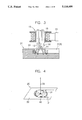
- FIG. 3 is an enlarged cross-sectional view of electromagnetic means of the apparatus shown in FIG. 2;
- FIG. 4 is an explanatory illustration showing the mechanism for generating a Lorentz force in a molten metal layer
- FIG. 5 is a cross-sectional view of a chilled layer formed by the apparatus shown in FIG. 2;
- FIG. 6 is a cross-sectional view of a chilled layer experimentally formed for the purpose of evaluating the chilled layers formed by the apparatus shown in FIG. 2;
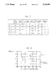
- FIG. 7 is a table showing the properties of chilled layers, for various flux densities of magnetic fields, formed by the apparatus shown in FIG. 2;
- FIG. 8 is an explanatory cross-sectional view of a chilled layer for illustrating evaluation properties, such as the depth, or thickness, of a chilled layer A in a cam top surface and the depth of indentation, or depression, B in the chilled layer;
- FIG. 9 is a diagram showing the properties of the chilled layers formed experimentally in terms of correlation between the width of the chilled layer and the flux density of the magnetic field;
- FIG. 10 is a diagram showing the depth of indentation relative to A.C. current frequency.
- FIG. 11 is a diagram showing the hardness of the chilled layer relative to A.C. current frequency.
- FIG. 2 an apparatus for forming a chilled layer on a surface of a workpiece by remelting and hardening treatment in accordance with a preferred embodiment of the present invention is shown.
- the apparatus is shown as used to form a chilled layer in the surface of a cam of a camshaft for, for instance, driving valves of an automotive engine.
- the camshaft 20 having cams 21 (only one of which is shown) of ductile iron to be treated and formed with a chilled layer in the cam surface 22, which is roughly ground, is turned at a constant speed about an axis of rotation 24 thereof by a conventional mechanical drive mechanism 18.
- the apparatus comprises molten metal layer forming means 10, for melting the cam surface 22 of the cam 21 and agitating, or stirring, the melted metal of the cam surface 22.
- the molten metal layer forming means 10 comprises a heat energy generator 11, such as a laser beam generator, an electron beam generator, a tungsten inert gas (TIG) arc generator or the like, for generating a beam of heat energy, and a magnetic field generator, such as an A.C. electromagnetic coil 15.
- the heat energy generator 11, such as a tungsten inert gas (TIG) arc generator (which is hereinafter referred to as a beam torch), has a cylindrical hollow housing 12 and an electrode 13 housed in the housing 12 with its cone-shaped tip 14 projecting outside the housing 12.
- the electromagnetic coil 15, having a cylindrical hollow coil body, is coaxially mounted on the housing 12 of the beam torch 11.
- the molten metal layer forming means 10 is oscillated, or reciprocally moved, by a conventional mechanical drive mechanism 19 in a direction of the axis of rotation 24 of the camshaft 20 at a constant speed so as to cause a two dimensional relative movement with respect to the surface 22 of the cam 21 of the camshaft 20.
- the electromagnetic coil 15 is energized, or magnetized, by an alternating current from an alternating current power supply 30.
- the molten metal layer 3' solidifies with time, and is hardened, thereby forming a chilled layer 3 (see FIG. 3) in the cam surface 22.
- the electrode 13 directs the energy beam 31 to the cam surface 22 of the cam 21 rotating about the axis of rotation 24 so as to trace a locus 28, thereby forming the molten metal layer circumferentially over the peripheral surface 22 of the cam 21.
- the molten metal layer forming means 10 While the electrode 13 is energized and radiates and directs the energy beam 31, the molten metal layer forming means 10 also magnetizes the magnetic coil 15 with the alternating current so as to generate a magnetic field.
- the magnetic field 32 interacts with the energy beam 31, causing the energy beam 31 to flare, and thereby generates a force which acts in directions indicated by arrows 40, well known as a Lorentz force, in the melted metal layer 3', as is shown in FIG. 4. While the molten metal of the layer 3' is cooled and solidified, it is agitated, or stirred, by the force 40.
- the force 40 acts on the molten metal layer 3' in opposite, i.e., clockwise and counterclockwise, directions, as viewed in FIG. 4. These directions change alternately. Accordingly, the molten metal is vibrated substantially in a vertical direction and is, therefore, vigorously agitated, or stirred, so that the molten metal layer 3' is more precisely uniform in thickness. Agitating the molten metal with the Lorentz force 40 promotes heat-dissipation more rapidly from the molten metal layer, so as to accelerate the solidification of the molten metal layer 3'.
- Moving the electromagnetic means 10 in the axial direction causes a flow of the molten metal from the outer side of molten metal layer 3' toward the center.
- the speed of the energy beam 31 drops, and the beam may momentarily stop, in the axial direction, at the opposite extreme ends of the molten metal layer 3', the molten metal layer 3' becomes uniform in depth, or thickness, so as to form a uniform thickness of chilled layer 3, as is shown in FIG. 5.
- FIG. 6 showing a chilled layer 43 formed in the cam surface 22 of the cam 21 by the use of a conventional apparatus which has no magnetic coil.
- the chilled layer 43 is thicker at the opposite extreme side portions 42, where the energy beam drops its speed, or stops, than at the central portion 44, and causes a difference in depth, or thickness, therebetween, which is shown by a reference character d. Comparing the chilled layer 3 shown in FIG. 5 to the chilled layer 43 shown in FIG. 6, the effect of an apparatus in accordance with the present invention is apparent.
- FIGS. 7 to 9 the results of several experiments conducted in order to make a comparison of the invention and a comparative conventional example, are shown.
- the experiments 1, 2 and 3 were carried out with a sample cam having a width of approximately 17.5 mm which was made of ductile iron and the surface of which was roughly ground.
- the apparatus used was a device such as a TIG device with an electromagnetic coil.
- Table I of FIG. 7 exhibits the results of these experiments for different currents of 7, 5 and 3 Amperes (A) so as to generate different flux densities of electromagnetic fields, such as 390, 280 and 170 gauss, respectively.
- the same apparatus was used with the same sample, but no electromagnetic field was generated. The electric field was eliminated by shutting down the supply of alternating current to the electromagnetic coil of the TIG device.
- the table of FIG. 7 shows the width of the chilled layer of the cam top surface, in mm, the thickness, or depth, A of the chilled layer of the cam top surface from a designed cam top surface (see FIG. 8) in mm, the depth of indentation B of the cam top surface from the designed cam top surface (see FIG. 8), in mm, and the hardness of chilled layer of the cam top surface, in Hv units, for each experiment.
- the width of the chilled layer increasingly varies with an increase in flux densities of the electromagnetic field generated by the electromagnetic coil.
- Changes in thickness or depth A of the chilled layer, the depth of indentation B and the hardness of the chilled layer are small and within a range in which no adverse effects on the function of the cam are caused.
- FIG. 9 shows a diagram in terms of the relationship between the flux densities of the electromagnetic field and the width of the chilled layer for the experiments.
- the A.C. current frequency is preferably approximately 1.5 and 6.0 Hz.
- the change in direction of the Lorentz force 40 is insufficient for the molten metal to be agitated and to flow, so that the molten metal does not dissipate heat rapidly.
- the Lorentz force 40 changes direction too frequently, so as to impede the flow of molten metal. This also causes an stagnation in heat-dissipation.
Landscapes
- Chemical & Material Sciences (AREA)
- Engineering & Computer Science (AREA)
- Physics & Mathematics (AREA)
- Thermal Sciences (AREA)
- Crystallography & Structural Chemistry (AREA)
- Mechanical Engineering (AREA)
- Materials Engineering (AREA)
- Metallurgy (AREA)
- Organic Chemistry (AREA)
- Heat Treatment Of Articles (AREA)
Applications Claiming Priority (4)
| Application Number | Priority Date | Filing Date | Title |
|---|---|---|---|
| JP2053100A JPH03257116A (ja) | 1990-03-05 | 1990-03-05 | 再溶融硬化処理装置 |
| JP2-53100 | 1990-03-05 | ||
| JP13164090A JP3187037B2 (ja) | 1990-05-21 | 1990-05-21 | 再溶融硬化方法 |
| JP2-131640 | 1990-05-21 |
Publications (1)
| Publication Number | Publication Date |
|---|---|
| US5114499A true US5114499A (en) | 1992-05-19 |
Family
ID=26393812
Family Applications (1)
| Application Number | Title | Priority Date | Filing Date |
|---|---|---|---|
| US07/664,137 Expired - Fee Related US5114499A (en) | 1990-03-05 | 1991-03-04 | Method of forming chilled layer |
Country Status (4)
| Country | Link |
|---|---|
| US (1) | US5114499A (fr) |
| EP (1) | EP0445699B1 (fr) |
| KR (1) | KR940004030B1 (fr) |
| DE (1) | DE69120102T2 (fr) |
Cited By (5)
| Publication number | Priority date | Publication date | Assignee | Title |
|---|---|---|---|---|
| US5468308A (en) * | 1994-08-22 | 1995-11-21 | The Torrington Company | Surface treated cast iron bearing element |
| US5906053A (en) * | 1997-03-14 | 1999-05-25 | Fisher Barton, Inc. | Rotary cutting blade having a laser hardened cutting edge and a method for making the same with a laser |
| US6857255B1 (en) | 2002-05-16 | 2005-02-22 | Fisher-Barton Llc | Reciprocating cutting blade having laser-hardened cutting edges and a method for making the same with a laser |
| US20120111458A1 (en) * | 2009-07-15 | 2012-05-10 | Boguslaw Grabas | Method of increasing heat exchange surfaces and active surfaces of metal elements including, in particular, heat exchange surfaces |
| US20160175984A1 (en) * | 2014-12-17 | 2016-06-23 | Airbus Group Limited | Method and Apparatus for Distortion Control on Additively Manufactured Parts Using Wire Feed and Magnetic Pulses |
Families Citing this family (1)
| Publication number | Priority date | Publication date | Assignee | Title |
|---|---|---|---|---|
| DE4430220C2 (de) | 1994-08-25 | 1998-01-22 | Fraunhofer Ges Forschung | Verfahren zur Steuerung der Laserstrahlintensitätsverteilung auf der Oberfläche zu bearbeitender Bauteile |
Citations (8)
| Publication number | Priority date | Publication date | Assignee | Title |
|---|---|---|---|---|
| SU449456A1 (ru) * | 1972-12-01 | 1974-11-05 | Предприятие П/Я Г-4696 | Способ электроннолучевого оплавлени поверхности слитков |
| JPS53140249A (en) * | 1977-04-09 | 1978-12-07 | Kobe Steel Ltd | Method and apparatus for welding |
| US4190760A (en) * | 1976-05-14 | 1980-02-26 | Kobe Steel, Ltd. | Welding apparatus with shifting magnetic field |
| JPS58196362A (ja) * | 1982-05-10 | 1983-11-15 | Toyota Motor Corp | 鋳鉄製カムシヤフト及びその製造方法 |
| JPS60204834A (ja) * | 1984-03-28 | 1985-10-16 | Honda Motor Co Ltd | カムシヤフトのカム部の再溶融硬化処理方法 |
| JPS60258421A (ja) * | 1984-05-21 | 1985-12-20 | Honda Motor Co Ltd | カムシヤフトの再溶融硬化処理方法 |
| JPS6117372A (ja) * | 1984-07-03 | 1986-01-25 | Mitsubishi Heavy Ind Ltd | 磁気撹拌横向溶接方法 |
| US4652724A (en) * | 1984-05-07 | 1987-03-24 | Toyota Jidosha Kabushiki Kaisha | Method of producing a camshaft |
Family Cites Families (3)
| Publication number | Priority date | Publication date | Assignee | Title |
|---|---|---|---|---|
| BE637738A (fr) * | 1962-09-24 | 1900-01-01 | ||
| DE1224885B (de) * | 1964-07-02 | 1966-09-15 | Heraeus Gmbh W C | Verfahren zur Herstellung von Schmelzbloecken im Vakuum-Lichtbogenofen |
| IT1219974B (it) * | 1981-06-25 | 1990-05-24 | Fischer Ag Georg | Procedimento di tempra a rifusione |
-
1991
- 1991-03-04 EP EP91103226A patent/EP0445699B1/fr not_active Expired - Lifetime
- 1991-03-04 KR KR1019910003477A patent/KR940004030B1/ko not_active Expired - Fee Related
- 1991-03-04 DE DE69120102T patent/DE69120102T2/de not_active Expired - Fee Related
- 1991-03-04 US US07/664,137 patent/US5114499A/en not_active Expired - Fee Related
Patent Citations (8)
| Publication number | Priority date | Publication date | Assignee | Title |
|---|---|---|---|---|
| SU449456A1 (ru) * | 1972-12-01 | 1974-11-05 | Предприятие П/Я Г-4696 | Способ электроннолучевого оплавлени поверхности слитков |
| US4190760A (en) * | 1976-05-14 | 1980-02-26 | Kobe Steel, Ltd. | Welding apparatus with shifting magnetic field |
| JPS53140249A (en) * | 1977-04-09 | 1978-12-07 | Kobe Steel Ltd | Method and apparatus for welding |
| JPS58196362A (ja) * | 1982-05-10 | 1983-11-15 | Toyota Motor Corp | 鋳鉄製カムシヤフト及びその製造方法 |
| JPS60204834A (ja) * | 1984-03-28 | 1985-10-16 | Honda Motor Co Ltd | カムシヤフトのカム部の再溶融硬化処理方法 |
| US4652724A (en) * | 1984-05-07 | 1987-03-24 | Toyota Jidosha Kabushiki Kaisha | Method of producing a camshaft |
| JPS60258421A (ja) * | 1984-05-21 | 1985-12-20 | Honda Motor Co Ltd | カムシヤフトの再溶融硬化処理方法 |
| JPS6117372A (ja) * | 1984-07-03 | 1986-01-25 | Mitsubishi Heavy Ind Ltd | 磁気撹拌横向溶接方法 |
Non-Patent Citations (2)
| Title |
|---|
| Applicant s Admission on p. 2, Line 13 to p. 3, Line 2 (Japanese Unexamined Patent Publication No. 6 258421). * |
| Applicant's Admission on p. 2, Line 13 to p. 3, Line 2 (Japanese Unexamined Patent Publication No. 6-258421). |
Cited By (6)
| Publication number | Priority date | Publication date | Assignee | Title |
|---|---|---|---|---|
| US5468308A (en) * | 1994-08-22 | 1995-11-21 | The Torrington Company | Surface treated cast iron bearing element |
| US5906053A (en) * | 1997-03-14 | 1999-05-25 | Fisher Barton, Inc. | Rotary cutting blade having a laser hardened cutting edge and a method for making the same with a laser |
| US6857255B1 (en) | 2002-05-16 | 2005-02-22 | Fisher-Barton Llc | Reciprocating cutting blade having laser-hardened cutting edges and a method for making the same with a laser |
| US20120111458A1 (en) * | 2009-07-15 | 2012-05-10 | Boguslaw Grabas | Method of increasing heat exchange surfaces and active surfaces of metal elements including, in particular, heat exchange surfaces |
| US20160175984A1 (en) * | 2014-12-17 | 2016-06-23 | Airbus Group Limited | Method and Apparatus for Distortion Control on Additively Manufactured Parts Using Wire Feed and Magnetic Pulses |
| US10987755B2 (en) * | 2014-12-17 | 2021-04-27 | Airbus Defence and Space GmbH | Method and apparatus for distortion control on additively manufactured parts using wire feed and magnetic pulses |
Also Published As
| Publication number | Publication date |
|---|---|
| KR910016947A (ko) | 1991-11-05 |
| DE69120102T2 (de) | 1997-01-30 |
| DE69120102D1 (de) | 1996-07-18 |
| EP0445699A3 (en) | 1992-10-21 |
| KR940004030B1 (ko) | 1994-05-11 |
| EP0445699B1 (fr) | 1996-06-12 |
| EP0445699A2 (fr) | 1991-09-11 |
Similar Documents
| Publication | Publication Date | Title |
|---|---|---|
| US4157923A (en) | Surface alloying and heat treating processes | |
| EP0445699B1 (fr) | Procédé et dispositif de fabrication de surfaces trempées | |
| US4772340A (en) | Method of making iron-base articles having a remelted layer | |
| US6398881B1 (en) | Wear-resistant camshaft and method of producing the same | |
| WO2018043637A1 (fr) | Procédé de rugosification de surface de corps moulé métallique | |
| US4787944A (en) | Process for producing surface remelted chilled layer camshaft | |
| US20230249290A1 (en) | Laser deburring and chamfering method and system | |
| US4718952A (en) | Process for producing a remelted and chilled camshaft | |
| JPS61194166A (ja) | 再溶融硬化処理方法 | |
| US5965037A (en) | Inert gas electric arc welding process and torch for use therein | |
| JP2856431B2 (ja) | 再溶融硬化処理部品の製造方法 | |
| JPH0732173A (ja) | レーザクラッディング方法 | |
| JPH03257116A (ja) | 再溶融硬化処理装置 | |
| JPH02269524A (ja) | 鋳物の再溶融処理方法 | |
| JPH08246119A (ja) | 金属の表面処理装置 | |
| JPH0645065B2 (ja) | 軸端への肉盛溶接方法 | |
| JPH0124598B2 (fr) | ||
| Bergs et al. | Material Machining with Electron Beams (EBM) | |
| JPH0570832A (ja) | 再溶融硬化処理装置とその方法 | |
| JP4102353B2 (ja) | 強磁性体金属材料の表層溶融処理方法 | |
| JPS61227124A (ja) | リメルト処理方法 | |
| Matarneh et al. | Usage of Controlling Magnetic Fields Effect for Performance Improvement of Electric Arc Welding and Surfacing | |
| JPH07214307A (ja) | 金属表面の再溶融処理方法 | |
| JP2000239746A (ja) | 表面硬化処理法 | |
| JPH0426718A (ja) | 再溶融硬化方法 |
Legal Events
| Date | Code | Title | Description |
|---|---|---|---|
| AS | Assignment |
Owner name: MAZDA MOTOR CORPORATION, 3-1, SHINCHI, FUCHU-CHO, Free format text: ASSIGNMENT OF ASSIGNORS INTEREST.;ASSIGNOR:KUSUNOKI, HIROAKI;REEL/FRAME:005632/0995 Effective date: 19910228 |
|
| FPAY | Fee payment |
Year of fee payment: 4 |
|
| REMI | Maintenance fee reminder mailed | ||
| LAPS | Lapse for failure to pay maintenance fees | ||
| FP | Lapsed due to failure to pay maintenance fee |
Effective date: 20000519 |
|
| STCH | Information on status: patent discontinuation |
Free format text: PATENT EXPIRED DUE TO NONPAYMENT OF MAINTENANCE FEES UNDER 37 CFR 1.362 |