US5327690A - Erection workbench for constructing a frame - Google Patents
Erection workbench for constructing a frame Download PDFInfo
- Publication number
- US5327690A US5327690A US07/772,707 US77270791A US5327690A US 5327690 A US5327690 A US 5327690A US 77270791 A US77270791 A US 77270791A US 5327690 A US5327690 A US 5327690A
- Authority
- US
- United States
- Prior art keywords
- workbench
- column
- erection
- columns
- frame
- Prior art date
- Legal status (The legal status is an assumption and is not a legal conclusion. Google has not performed a legal analysis and makes no representation as to the accuracy of the status listed.)
- Expired - Fee Related
Links
Images


Classifications
-
- E—FIXED CONSTRUCTIONS
- E04—BUILDING
- E04G—SCAFFOLDING; FORMS; SHUTTERING; BUILDING IMPLEMENTS OR AIDS, OR THEIR USE; HANDLING BUILDING MATERIALS ON THE SITE; REPAIRING, BREAKING-UP OR OTHER WORK ON EXISTING BUILDINGS
- E04G3/00—Scaffolds essentially supported by building constructions, e.g. adjustable in height
- E04G3/28—Mobile scaffolds; Scaffolds with mobile platforms
-
- E—FIXED CONSTRUCTIONS
- E04—BUILDING
- E04G—SCAFFOLDING; FORMS; SHUTTERING; BUILDING IMPLEMENTS OR AIDS, OR THEIR USE; HANDLING BUILDING MATERIALS ON THE SITE; REPAIRING, BREAKING-UP OR OTHER WORK ON EXISTING BUILDINGS
- E04G21/00—Preparing, conveying, or working-up building materials or building elements in situ; Other devices or measures for constructional work
- E04G21/14—Conveying or assembling building elements
- E04G21/16—Tools or apparatus
Definitions
- This invention relates to an erection workbench for constructing a frame of a building and a frame construction method by utilizing the erection workbench, and more particularly, to an erection workbench for constructing a frame of a building and a frame construction method for assembling preliminarily prepared beam members and column members made of a steel frame structure or a precast concrete structure or the like at a construction site.
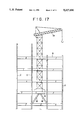
- FIG. 17 In constructing a frame of a building by assembling column members and beam members which are made of structural steel or precast concrete at a work site, a method shown in FIG. 17 is generally employed.
- the process for constructing the frame of the building is progressed by lifting up the column members and the beam members with the use of a lifting crane placed on the circumferences of the building to be erected or on the constructed beams or slabs for the building.
- Such column members and beam members are assembled and combined under the condition having no work scaffolds.
- an arm derrick type tower crane, an arm horizontal type tower crane or the like, as shown in FIG. 17, are used for lifting the beam and column members.
- the cranes to be used in a construction site are difficult to change positions once they are fixed on the frame of the building or on the ground, and thus, it is preferable in the conventional process to utilize relatively large cranes which can lift the column and beam members to the position higher than the top of the building to be built so that these cranes can be used until the final stage of the construction of the building without changing the positions. Further, for the sake of workability and efficiency, the numbers of cranes to be used in the construction area are limited to a certain small numbers.
- scaffolds cannot be provided to the columns and the beams until the assembly of frames is completed.
- the scaffold is a temporary platform used by workers in the construction of a building.
- the assembling work in the conventional method has to be practiced in the condition having no scaffolds. Therefore, the construction workers have to practice under the very dangerous condition where they directly climb the columns and walk on the beams, resulting in the serious shortage of workers.
- the further object of the present invention is to provide a frame construction process for constructing frames and an erection workbench for assembling frames which is capable of automatic execution of the assembly works and, as a result, to overcome a labor shortage problem.
- an erection workbench for constructing frames (hereinafter referred to as "erection workbench") and a method for constructing frames are comprised as described below.
- the erection workbench of the present invention is comprised of a plurality of extension columns positioned in an inside area defined by, for example, four column members which form the minimum unit of the frame to be constructed, a workbench which is provided at the intermediate position of the extension columns, a roof installed at the top of the extension column, and a lifting crane attached vertically to the workbench or to the roof.
- the extension column is composed of a fixed column supported by the beam members of the frame at the downstairs side and a column base connected expandably to the lower end of the fixed column.
- the extension column includes a drive mechanism such as a hydraulic cylinder or a winch so that the column base can elongate from the fixed column and thus lift up the workbench upstairs.
- wheels are provided on tie-beams which are attached to the lower end portion of the column base or to the lower end of the fixed column of the extension column so that the erection workbench can slidably move in a horizontal direction back and forth on the beam members.
- the erection workbench not only climbs up the frame of the building but also freely changes positions in the horizontal direction of the frame.
- Another aspect of the present invention is an erection workbench which has a plurality of workbenches, the top of which also serves as a roof.
- various kinds of construction machines including a crane can be installed for further increasing the working efficiency and flexibility.
- a method for constructing frames according to the present invention is accomplished by the following process.
- the column members and the beam members of the frame to be assembled are lifted up to upstairs by the lifting crane installed vertically to the workbench or to the roof. Then, the column members and the beam members are assembled into a frame of the upstairs. After assembling the frame of the upstairs, the fixed columns of the extension columns are released. The base columns of the extension columns elongate with respect to the beam members of the downstairs and, as a result, push up the workbench to the next level of the frame to be assembled. The fixed columns of the extension columns are attached to the beam members of the upstairs which have just assembled prior to the climbing up of the workbench. The elongated base columns are retracted into the extension columns. Thus, the erection workbench has completed in climbing up one layer of the frame.
- the frames are constructed in turn toward an upper direction by repeating such procedures of lifting up assembling materials while at the same time the erection workbench moves in both vertical and horizontal directions until the assembly work for the frame of the building is finished.
- the frames are also constructed in turn in a lateral direction while moving the erection workbench laterally by sliding it on the already constructed beams.
- the filling and loading of the frame materials, i.e., beam members and column members on the erection workbench is practiced by the workbench itself while making the extension columns support the workbench.
- the workbench of the present invention not only works as a scaffold for workers but provides expandable and retractable scaffolds at the end of the workbench.
- the erection workbench of the present invention obviates the large scale cranes required in the conventional method, since the erection workbench can climb up the frame one layer by one layer while bringing the frame materials from the ground and assembling such materials into the frame.
- the erection workbench in accordance with the present invention can also move horizontally on the beam members by providing wheels on the workbench which slide on the beam members that have been.
- erection workbench of the present invention moves around horizontally from one frame unit to the other and, as a result, it can obviate a tower crane having a long lifting arm since the erection workbench can reach any position of the building under construction. Since no large-scale tower crane is needed for lifting up the column members and the beam members, in accordance with the present invention, the reinforcement of the column members and the beam members for fixing the large cranes becomes unnecessary, which greatly improves reduction of cost and time for construction of a building.
- the safety in execution of the assembly work can greatly be improved by practicing the assembly work of the columns and the beams on the workbench and on the scaffolds which are provided at the ends of the workbench.
- a series of execution such as welding and bolting works at the time of column and beam assembly can be made automatically by loading various constructing robots such as an assembling robot and a welding robot on the workbench.
- any weather influences can be overcome and the efficiency in executions can be improved by erecting a roof at the top of workbench.
- FIG. 1 is a side view showing the major structure and procedure for constructing a frame of a building by an erection workbench in accordance with the present invention.
- FIG. 2 is a plan view showing the frame and the erection workbench of FIG. 1.
- FIG. 3 is a side view showing the erection workbench and the frame of the present invention.
- FIGS. 4 and 5 are side views showing the details of the support arms of the extension column at the storing status of the column base, and also are fragmentary views taken in X and Y directions of FIG. 7, respectively.
- FIG. 6 is a fragmentary view showing the modification of the extension column of FIGS. 4 and 5 and taken in the Y direction of FIG. 7.
- FIG. 7 is a partial plan view of FIG. 2 showing the extension column of the workbench, the column member and the beam member.
- FIG. 8 is a side view showing the essential feature of erection workbench and the process of constructing the frame in accordance with the another embodiment of the present invention.
- FIG. 9 is a plan view showing frame and the erection workbench of the embodiment of FIG. 8;
- FIG. 10 is a side view showing the erection workbench of FIG. 8 having the wheels.
- FIGS. 11 through 13 show the wheel-fixing portion of the erection workbench of the present invention, wherein FIGS. 11 and 13 are plan views and FIG. 12 is a longitudinal sectional view.
- FIGS. 14, 15 and 16 show further embodiment of the erection workbench in accordance with the present invention, wherein FIG. 14 is a schematic plan view, FIG. 15 is a sectional view taken along the line a--a of FIG. 14, and FIG. 16 is a sectional view taken along the line b--b of FIG. 14, respectively.
- FIG. 17 is a side view showing a prior art structure and process for constructing frames of a building.
- the present invention is an erection workbench for constructing a frame of a building composed of column members and beam members of steel structure or precast concrete structure and a method for constructing the frame by using the erection workbench.
- the frame is constructed by assembling the beam member B and the column members C by utilizing the erection workbench A of the present invention.
- the erection workbench A is comprised of a plurality of extension columns 2 positioned close to the column member C, a workbench 1 attached at the intermediate position of the extension columns 2, a roof 4 provided at the top of the extension column 2, and a lifting crane 3 attached vertically to the workbench 1 or to the roof 4.
- Each of the extension columns 2 of the erection workbench A is disposed in an area of the buliding defined by the corresponding column members C.
- Four of the column members C form the minimum unit of the frame to be constructed for the building as shown in FIG. 2.
- the workbench 1 has the flat area defined by the four corners of this minimum unit.
- the lifting crane 3 is suspended from the workbench 1 as shown in FIGS. 1 and 3.
- the lifting crane 3 is attached to the workbench 1 in a manner which is freely movable in a horizontal direction by using, for example, a monorail or other means for increasing efficiency and flexibility of the construction work.
- the extension column is composed of a fixed column 2a supported by the beam members B of the frame at the downstairs side and a column base 2b connected expandably and retractably to the lower end of the fixed column 2a as shown in FIGS. 1 to 3.
- the extension column 2 includes a drive mechanism such as a hydraulic cylinder or a winch so that the column base can elongate from the fixed column and thus the extension column push up the workbench to the upstairs.
- Support arm 2c for connecting the erection workbench A to the beam member B are projected on the lower end of the fixed column 2a so that the support arm 2c can be attached on the nearest beam member B as illustrated in FIG. 3.
- a plurality of the support arms 2c are preferably used in an orthogonal manner with each other to strengthen the connection with the beam members B.
- the support arms 2c are so arranged that they can extend from the fixed column 2a and also retracted into the fixed column 2a. The reason of this retractable and extendable structure is to avoid the collision against the upstairs beams B when the workbench 1 is raised to the upstairs. Therefore, the support arm 2c can also be attached to the fixed column 2a in a hinge structure.
- FIG. 2 shows a plan view taken along lines a--a and b--b in FIG. 1.
- the fixed column 2a has a sufficient length passing through the workbench 1 from the beam B on the underside of the workbench 1 and leading to the roof 4 (FIGS. 1 and 3).
- the column base 2b is pulled back for storing it within the fixed column 2a as shown in the right side of FIG. 1.
- the column base 2b has a support arm 2d at its lower end for connecting the column base 2b to the beam member B.
- the support arm 2d is used for receiving the load given at the time when the extension column 2 expand for the erection workbench A to climb up the frame.
- the weight of the workbench A is provided to the beam members B through the base column 2b and the support arm 2d.
- a plurality of the support arms 2d are preferably used in an orthogonal manner with each other to strengthen the connection with the beam members B. Further, in the preferred embodiment of FIGS. 1 to 3 the support arms 2d are formed so that they can extend and retract with respect to the base column 2b.
- FIGS. 4 through 7 show examples of mechanisms for connecting the extension columns 2 to the beam members B at the storing time of the column base 2b.
- FIGS. 4 and 5 are fragmentary views taken at lines X and Y of FIG. 7, respectively.
- the load of the erection workbench A is supported by both the support arm 2c for the fixed column 2a and the support arm 2d for the column base 2b stored in such a condition, for example, that the end portion lower than the support arm 2C is exposed as shown in FIGS. 4 and 5.
- FIG. 6 shows the modification of FIGS. 4 and 5.
- the column base 2b is completely stored within the fixed column 2a
- the support arm 2d for the column base 2b is projected from the cut-out formed at the lower end of the fixed column 2a
- the load of the erection workbench A is supported by the projected support arm 2d of the column base 2b and the support arm 2c for the fixed column 2a.
- the column base 2b is stored in the fixed column 2a. After the assembly of a single layer of the frame is completed, the column base 2b expands to raise the fixed column 2a and the workbench 1 to the upper layer. Then the column base 2b is pulled back into the fixed column 2a to be stored after the erection workbench A is fixed to the beam members B in the upper layer.
- this extension operation is undertaken by a drive mechanism such as a hydraulic cylinder or a winch provided in the extension column 2.
- the roof 4 is supported by the fixed column 2a which continues from the four corners of the workbench 1 to the fixed column 2a of the extension column 2.
- the roof 4 has a flat area larger than that of the workbench 1, and its circumference overhangs from the workbench 1 as illustrated in FIG. 3. The working condition on the workbench 1 will be improved and thus the efficiency of construction works can be improved by using the material penetrated by light for the roof 4.
- the lifting crane 3 is provided to the workbench 1, and if necessary, it is also possible to be suspended from the roof 4.
- another type of the lifting cranes 5 are attached to the external side of the extension column 2 for lifting mainly the column members C or the beam members B.
- These lifting cranes 3 and 5 are used not only for the setting of the column members C and the beam members B into the frame but also for making exterior structures such as a curtain wall.
- movable scaffolds 1a overhanging horizontally from the workbench 1 are provided to improve the efficiency of the construction works.
- the construction workers can practice their jobs freely on the workbench 1 and on the movable scaffolds 1a, which greatly improves the working efficiency and safety.
- the scaffolds 1a are withdrawn from the outside of the workbench 1 when it is used, and stored inside of workbench 1 when the erection workbench A moves up to the upstairs.
- the erection workbench A of the present invention can also be applied to the frames with the different size of the minimum unit, i.e., the minimum frame unit of considerably larger than the size of the workbench 1 of the erection workbench A.
- the erection workbench A is provided at the further inside of the four columns C corresponding to the size of the flat area.
- the erection workbench A can be provided on every frame unit of a single layer as shown in FIGS. 1 and 2, and is independently lifted to the upper layer, respectively. As will be described later, the erection workbench A of the other embodiment can move around not only in a vertical direction but also in a horizontal direction. Thus, in that case, only one or two erection workbenches of the present invention will be satisfactory for the construction of even a large scale building.
- the procedure for executing layers of the frame structure is described.
- the erection workbench A is supported by the beam member B by fixing the fixed column 2a to the beam member B on the downstairs side (m) by the support arms 2c as shown on the left side in FIG. 1.
- the to the beam member B on the downstairs side (m) by the base columns 2b are stored within the fixed columns 2a.
- the column members C and the beam members B are erected and connected by lifting up these members from the ground for instance, with the use of the lifting cranes 3 and the outside lifting crane 5 which are suspended from the workbench 1 and the roof 4 and the fixed column 2a.
- other works such as assembling the downstairs floor slabs are executed by the lifting crane 3 attached to the underside of the workbench 1.
- the support arms 2d at the lower end of the base column 2b are attached to the beam members B on the down layer (k) for supporting the weight of the erection workbench A through the base columns 2b instead of fixed columns 2a.
- the support arms 2c at the bottom of the fixed columns 2a are disconnected from the beam members B.
- the support cylinder (not shown) the erection workbench A including the arms 2c are taken out from the fixed column 2a and connected to the beam members B of the layer (m) as shown in the center of FIG. 1. Then, the support arms on the column base 2b are retracted to be stored inside of the fixed column 2a, by the process as shown at the right side of FIG. 1.
- the frame in the layer (n) is assembled by hoisting the column members C and the beam members B with the use of the lifting cranes 3 and 5 as describe above. By repeating this procedure, the frame of the building is assembled step by step until the top of the building.
- FIGS. 8 through 13 show other embodiments of the erection workbench for constructing frames in accordance with the present invention.
- a plurality of tie-beams 6 which are parallel with each other and are horizontally attached to the lower end of the fixed columns 2a of the extension columns 2.
- a plurality of wheels 7 for slidably moving the workbench 1 on the erected beam members B by a drive mechanism (not shown) are installed on the tie-beams 6 at a certain interval in a longitudinal direction as shown in FIG. 8.
- the erection workbench A can move in a horizontal direction from one frame unit to the other.
- the wheels 7 are arranged so that they can reciprocally and axially move on the beam members B (best shown in FIGS. 11 and 12) or rotatably move by means of hinges (best shown in FIG. 13).
- the wheels 7 can also be arranged attachably or detachably (not shown) from the tie-beams 6.
- the erection workbench A can freely move in a horizontal direction either front and rear or left and right on the already erected beams B in addition to move vertically. Furthermore, in case where the tie-beams 6 are erected at the four corners of the fixed column 2a and the wheels 7 are respectively provided, the erection workbench A can freely move in a horizontal plane of either front, rear, left or right direction.
- the process for constructing frames is described as below.
- the erection workbench A is supported to the beam members B by fixing the fixed columns 2a to the beam members B on the downstairs through the support arms 2c by the process shown in the left side of FIG. 8, and at the same time, the wheels 7 are locked so as not to rotate at this stage.
- the column bases 2b are also stored in the fixed columns 2a.
- the fastening for the support arms 2c and the lock for the wheels 7 are temporarily released so as to make the erection workbench A movable. Furthermore, as the total weight of the erection workbench A loads on the wheels 7 in such a condition, at least four wheels 7 are provided on one side of the erection workbench A to firmly support the erection workbench A.
- the erection workbench A is slid on the beam members B and moved laterally to the next frame unit.
- the erection workbench A is connected to the beam members B by fixing the fixed column 2a to the beam members B again by the support arms 2c.
- it is desirable that the works are practiced in the condition that the erection workbench A is completely fixed to the beam members B by the support arms 2c.
- the work can be performed by supporting the erection workbench A only by the wheels 7 without fixing the extension columns 2 to the beam members B by the support arms 2c.
- both the workbench 1 and the fixed column 2a are moved upwards for one layer by extending the column bases 2b, and the erection workbench A is supported to the upstairs beams B by attaching the support arms 2c from the fixed columns 2a onto the upstairs beam members B.
- the column base 2b is stored in the fixed column 2a.
- the wheels 7 are aligned on the upstairs beams B for the horizontal movement.
- FIGS. 14, 15, and 16 show further embodiments of the erection workbench A according to the present invention.
- a workbench 8 is provided to be used both as a roof and a workbench, on which various construction machines corresponding to the object to be used as a lifting crane 9 or the like are provided.
- Other configurations are substantially the same as the preceding embodiments.
- the erection workbench is provided to be fit to the minimum unit of the frame, the weight of each workbench is small and no large force is needed for lifting the erection workbench itself.
- the lifting crane attached to the erection workbench can be a comparatively lower capacity. Therefore, as no large tower crane of a conventional type is needed and it can do without any reinforcement of the frames, the large cost reduction can be attained.
- the term of works can be shortened, and the day off of workers due to rainy weather is not needed, which results further increase in the efficiency in the executions.
- the erection workbench can move up and down in the vertical direction, and right and left horizontally, the executable range of an erection workbench is greatly increased. Therefore, especially when the size of building to be constructed is large, the construction works can be proceeded with an extremely high efficiency by employing the small number of the erection workbenches of the present invention, resulting in a large cost reduction.
Landscapes
- Engineering & Computer Science (AREA)
- Architecture (AREA)
- Mechanical Engineering (AREA)
- Civil Engineering (AREA)
- Structural Engineering (AREA)
- Conveying And Assembling Of Building Elements In Situ (AREA)
Priority Applications (1)
| Application Number | Priority Date | Filing Date | Title |
|---|---|---|---|
| US08/209,296 US5371993A (en) | 1990-06-20 | 1994-03-10 | Frame construction method |
Applications Claiming Priority (8)
| Application Number | Priority Date | Filing Date | Title |
|---|---|---|---|
| JP2-270059 | 1990-10-08 | ||
| JP27005990A JPH0718246B2 (ja) | 1990-10-08 | 1990-10-08 | 架構の構築方法 |
| JP33423390A JPH0721250B2 (ja) | 1990-11-30 | 1990-11-30 | 架構の構築方法及びその構築用作業架台 |
| JP2-334233 | 1990-11-30 | ||
| JP3-11960 | 1991-02-01 | ||
| JP1196091 | 1991-02-01 | ||
| JP3-148372 | 1991-06-20 | ||
| JP14837291A JPH0718252B2 (ja) | 1991-02-01 | 1991-06-20 | 架構構築用架設作業台 |
Related Child Applications (1)
| Application Number | Title | Priority Date | Filing Date |
|---|---|---|---|
| US08/209,296 Division US5371993A (en) | 1990-06-20 | 1994-03-10 | Frame construction method |
Publications (1)
| Publication Number | Publication Date |
|---|---|
| US5327690A true US5327690A (en) | 1994-07-12 |
Family
ID=33545416
Family Applications (2)
| Application Number | Title | Priority Date | Filing Date |
|---|---|---|---|
| US07/772,707 Expired - Fee Related US5327690A (en) | 1990-06-20 | 1991-10-07 | Erection workbench for constructing a frame |
| US08/209,296 Expired - Fee Related US5371993A (en) | 1990-06-20 | 1994-03-10 | Frame construction method |
Family Applications After (1)
| Application Number | Title | Priority Date | Filing Date |
|---|---|---|---|
| US08/209,296 Expired - Fee Related US5371993A (en) | 1990-06-20 | 1994-03-10 | Frame construction method |
Country Status (4)
| Country | Link |
|---|---|
| US (2) | US5327690A (de) |
| EP (1) | EP0480683B1 (de) |
| AU (1) | AU651616B2 (de) |
| DE (1) | DE69111018T2 (de) |
Cited By (9)
| Publication number | Priority date | Publication date | Assignee | Title |
|---|---|---|---|---|
| US20110289862A1 (en) * | 2009-02-09 | 2011-12-01 | 3L-Innogenie Inc. | Construction system and method for multi-floor buildings |
| US20120319341A1 (en) * | 2010-08-06 | 2012-12-20 | Sam Koffski | Portable expandable workbench |
| WO2013171359A1 (es) * | 2012-05-18 | 2013-11-21 | Structural Research,S.L. | Grúa telescópica autotrepante y procedimiento de montaje de torres prefabricadas de hormigón |
| US9890545B1 (en) * | 2016-11-14 | 2018-02-13 | Steven James Bongiorno | Erection system |
| CN112459232A (zh) * | 2020-10-13 | 2021-03-09 | 福建金启点实业有限公司 | 一种钢结构建筑及其智能施工方法 |
| CN113955659A (zh) * | 2020-11-25 | 2022-01-21 | 广州三叠纪元智能科技有限公司 | 爬架控制方法、电箱和存储介质 |
| CN114575581A (zh) * | 2022-03-18 | 2022-06-03 | 河南中之正工程技术研究院有限公司 | 一种具有图像识别的施工平台及其升降控制方法 |
| CN114776037A (zh) * | 2022-03-31 | 2022-07-22 | 中国建筑第八工程局有限公司 | 一种装配式高大条板安装设备 |
| CN116497949A (zh) * | 2023-05-15 | 2023-07-28 | 浙江东南网架股份有限公司 | 柱顶永久箍形提升节点及其控制方法 |
Families Citing this family (13)
| Publication number | Priority date | Publication date | Assignee | Title |
|---|---|---|---|---|
| AU722381B2 (en) * | 1996-04-23 | 2000-08-03 | Mannesmann Aktiengesellschaft | Travelling crane |
| AUPN943196A0 (en) * | 1996-04-23 | 1996-05-16 | Elischer, Julius William | Demountable overhead travelling crane |
| US5908088A (en) * | 1996-12-27 | 1999-06-01 | Pflow Industries Inc. | Hydraulic drive mechanism for a vertical conveyor |
| GB2323106B (en) * | 1997-03-20 | 2001-10-24 | Trilogy Entertainments Plc | Elevated accomodation assembly |
| US6679025B1 (en) * | 2000-12-08 | 2004-01-20 | Process Marketing, Inc. | Modular tower |
| US7290672B2 (en) * | 2001-03-21 | 2007-11-06 | Federated Equipment Co. Llc | Tower crane device |
| US6751813B2 (en) * | 2002-01-29 | 2004-06-22 | Chung Jing-Yau | Portable hygienic water jet having sanitary disposable nozzle protector on non-disposable nozzle |
| KR100610447B1 (ko) * | 2004-09-06 | 2006-08-09 | 현대자동차주식회사 | 폐자동차의 액상류 회수 시스템 |
| US7979981B2 (en) * | 2005-05-23 | 2011-07-19 | Innovequity Inc. | Automated construction system |
| US20080078624A1 (en) * | 2006-07-27 | 2008-04-03 | Pflow Industries, Inc. | Vertical conveyor with hydraulic drive |
| US20080263995A1 (en) * | 2007-04-27 | 2008-10-30 | Innovequity Inc. | Automated construction system with interlocking panels |
| NO340821B1 (no) * | 2016-06-21 | 2017-06-26 | Prezioso Linjebygg As | Løftearrangement |
| CN117260152B (zh) * | 2023-11-17 | 2024-02-02 | 山西中德铝业有限公司 | 一种铝型材加工用同步转动焊接装置 |
Citations (15)
| Publication number | Priority date | Publication date | Assignee | Title |
|---|---|---|---|---|
| FR64548E (fr) * | 1953-08-18 | 1955-11-14 | Ossature de charpente en béton armé | |
| FR1181529A (fr) * | 1957-08-22 | 1959-06-16 | Toisoul Nadot Ets | échafaudage mobile, notamment pour la construction de cheminées |
| GB837036A (en) * | 1956-06-07 | 1960-06-09 | Siemens Bauunion Gmbh | Improvements in or relating to staging devices for use in building |
| FR1305537A (fr) * | 1961-08-22 | 1962-10-05 | Potain & Cie Ets F | Perfectionnements aux grues à mât réglable en hauteur à l'intérieur d'un bâtiment |
| US3217896A (en) * | 1962-11-06 | 1965-11-16 | Cannella Gaspari | Self-elevating building crane |
| US3802136A (en) * | 1972-01-26 | 1974-04-09 | Gottwald Kg Leo | Extendible crane boom formed of telescopic box-shaped sections |
| DE2312509A1 (de) * | 1973-03-13 | 1974-10-10 | Kresic Marjan Dipl Ing | Verfahren zur errichtung eines mehrgeschoessigen bauwerkes aus stahlbeton, sowie allwetter- vorrichtung zur ausfuehrung des verfahrens |
| US3877582A (en) * | 1971-08-06 | 1975-04-15 | Charley H Moore | Panel positioning apparatus |
| US3974618A (en) * | 1974-03-18 | 1976-08-17 | Pablo Ortega Cortina | Method of and means for multi-story building construction |
| US4027802A (en) * | 1976-08-03 | 1977-06-07 | Reynolds Francis E | Building panel positioner |
| US4482130A (en) * | 1983-02-01 | 1984-11-13 | Paredes Jose R | Vertical lifting and placing apparatus |
| US4657112A (en) * | 1986-04-25 | 1987-04-14 | Up-Right, Inc. | Mast construction for pedestal scaffold |
| US4884938A (en) * | 1986-12-01 | 1989-12-05 | Kawasaki Jukogyo Kabushiki Kaisha | Apparatus for handling large-sized articles |
| WO1990009497A1 (en) * | 1989-02-08 | 1990-08-23 | Lubeca Construction Systems Pty. Ltd. | Building construction system |
| US5018923A (en) * | 1988-11-09 | 1991-05-28 | Paul Wurth S.A. | Automated bricklaying apparatus |
Family Cites Families (4)
| Publication number | Priority date | Publication date | Assignee | Title |
|---|---|---|---|---|
| US3858688A (en) * | 1972-03-10 | 1975-01-07 | G W Galloway Company | Self-contained mobile extendable tower |
| US3851854A (en) * | 1973-07-05 | 1974-12-03 | F Roybal | Construction robot |
| US4752102A (en) * | 1982-04-16 | 1988-06-21 | Rasmussen Keith O | Elevating and supporting apparatus |
| AU626320B2 (en) * | 1988-09-05 | 1992-07-30 | Ohbayashi Corporation | Construction apparatus and construction method |
-
1991
- 1991-09-13 AU AU83881/91A patent/AU651616B2/en not_active Ceased
- 1991-10-07 US US07/772,707 patent/US5327690A/en not_active Expired - Fee Related
- 1991-10-08 DE DE69111018T patent/DE69111018T2/de not_active Expired - Fee Related
- 1991-10-08 EP EP91309228A patent/EP0480683B1/de not_active Expired - Lifetime
-
1994
- 1994-03-10 US US08/209,296 patent/US5371993A/en not_active Expired - Fee Related
Patent Citations (15)
| Publication number | Priority date | Publication date | Assignee | Title |
|---|---|---|---|---|
| FR64548E (fr) * | 1953-08-18 | 1955-11-14 | Ossature de charpente en béton armé | |
| GB837036A (en) * | 1956-06-07 | 1960-06-09 | Siemens Bauunion Gmbh | Improvements in or relating to staging devices for use in building |
| FR1181529A (fr) * | 1957-08-22 | 1959-06-16 | Toisoul Nadot Ets | échafaudage mobile, notamment pour la construction de cheminées |
| FR1305537A (fr) * | 1961-08-22 | 1962-10-05 | Potain & Cie Ets F | Perfectionnements aux grues à mât réglable en hauteur à l'intérieur d'un bâtiment |
| US3217896A (en) * | 1962-11-06 | 1965-11-16 | Cannella Gaspari | Self-elevating building crane |
| US3877582A (en) * | 1971-08-06 | 1975-04-15 | Charley H Moore | Panel positioning apparatus |
| US3802136A (en) * | 1972-01-26 | 1974-04-09 | Gottwald Kg Leo | Extendible crane boom formed of telescopic box-shaped sections |
| DE2312509A1 (de) * | 1973-03-13 | 1974-10-10 | Kresic Marjan Dipl Ing | Verfahren zur errichtung eines mehrgeschoessigen bauwerkes aus stahlbeton, sowie allwetter- vorrichtung zur ausfuehrung des verfahrens |
| US3974618A (en) * | 1974-03-18 | 1976-08-17 | Pablo Ortega Cortina | Method of and means for multi-story building construction |
| US4027802A (en) * | 1976-08-03 | 1977-06-07 | Reynolds Francis E | Building panel positioner |
| US4482130A (en) * | 1983-02-01 | 1984-11-13 | Paredes Jose R | Vertical lifting and placing apparatus |
| US4657112A (en) * | 1986-04-25 | 1987-04-14 | Up-Right, Inc. | Mast construction for pedestal scaffold |
| US4884938A (en) * | 1986-12-01 | 1989-12-05 | Kawasaki Jukogyo Kabushiki Kaisha | Apparatus for handling large-sized articles |
| US5018923A (en) * | 1988-11-09 | 1991-05-28 | Paul Wurth S.A. | Automated bricklaying apparatus |
| WO1990009497A1 (en) * | 1989-02-08 | 1990-08-23 | Lubeca Construction Systems Pty. Ltd. | Building construction system |
Cited By (12)
| Publication number | Priority date | Publication date | Assignee | Title |
|---|---|---|---|---|
| US20110289862A1 (en) * | 2009-02-09 | 2011-12-01 | 3L-Innogenie Inc. | Construction system and method for multi-floor buildings |
| US8544238B2 (en) * | 2009-02-09 | 2013-10-01 | 3L-Innogenie Inc. | Construction system and method for multi-floor buildings |
| US20120319341A1 (en) * | 2010-08-06 | 2012-12-20 | Sam Koffski | Portable expandable workbench |
| WO2013171359A1 (es) * | 2012-05-18 | 2013-11-21 | Structural Research,S.L. | Grúa telescópica autotrepante y procedimiento de montaje de torres prefabricadas de hormigón |
| ES2435211A1 (es) * | 2012-05-18 | 2013-12-16 | Structural Research, S.L. | Grúa telescópica autotrepante y procedimiento de montaje de torres prefabricadas de hormigón |
| US9890545B1 (en) * | 2016-11-14 | 2018-02-13 | Steven James Bongiorno | Erection system |
| CN112459232A (zh) * | 2020-10-13 | 2021-03-09 | 福建金启点实业有限公司 | 一种钢结构建筑及其智能施工方法 |
| CN113955659A (zh) * | 2020-11-25 | 2022-01-21 | 广州三叠纪元智能科技有限公司 | 爬架控制方法、电箱和存储介质 |
| CN113955659B (zh) * | 2020-11-25 | 2023-09-08 | 广州三叠纪元智能科技有限公司 | 爬架控制方法、电箱和存储介质 |
| CN114575581A (zh) * | 2022-03-18 | 2022-06-03 | 河南中之正工程技术研究院有限公司 | 一种具有图像识别的施工平台及其升降控制方法 |
| CN114776037A (zh) * | 2022-03-31 | 2022-07-22 | 中国建筑第八工程局有限公司 | 一种装配式高大条板安装设备 |
| CN116497949A (zh) * | 2023-05-15 | 2023-07-28 | 浙江东南网架股份有限公司 | 柱顶永久箍形提升节点及其控制方法 |
Also Published As
| Publication number | Publication date |
|---|---|
| AU8388191A (en) | 1992-04-09 |
| AU651616B2 (en) | 1994-07-28 |
| EP0480683A1 (de) | 1992-04-15 |
| DE69111018D1 (de) | 1995-08-10 |
| US5371993A (en) | 1994-12-13 |
| EP0480683B1 (de) | 1995-07-05 |
| DE69111018T2 (de) | 1996-02-01 |
Similar Documents
| Publication | Publication Date | Title |
|---|---|---|
| US5371993A (en) | Frame construction method | |
| US5255489A (en) | Construction apparatus for buildings and constructing method therewith | |
| US5022199A (en) | Construction apparatus and construction method | |
| JP7346246B2 (ja) | 重量物移動装置を用いた重量物の移動方法及び重量物移動装置 | |
| US5881504A (en) | Temporary frame system for construction | |
| CN114370150B (zh) | 一种装配式液压升降平台及其使用方法 | |
| JPH0483060A (ja) | 建築物構造 | |
| JPH08100517A (ja) | 昇降式作業台 | |
| JP2957328B2 (ja) | 周辺保持自昇式建築工法 | |
| KR100301573B1 (ko) | 건축 공사용 안전펜스 | |
| JPH0571225A (ja) | 全天候型仮設屋根 | |
| CN111747313A (zh) | 一种仓储物流建筑中预制梁吊装施工方法 | |
| CN215208144U (zh) | 一种架设设备 | |
| JPH08245176A (ja) | タワークレーン | |
| JP2008095373A (ja) | 移動用足場およびその仮設方法 | |
| CN113513149A (zh) | 一种附着式防护平台 | |
| JPH04297665A (ja) | 架構構築用架設作業台 | |
| JPH04146372A (ja) | 架構の構築方法 | |
| JPH04319174A (ja) | 仮設架台 | |
| JPH04319172A (ja) | 建物の架構構築装置 | |
| JP2934567B2 (ja) | 立体駐車場建設用作業ゴンドラ | |
| JP3002054U (ja) | 複数本の本設柱をタワーマストとするタワークレーン | |
| JPH03235838A (ja) | 仮設柱を用いたリフトアップ工法 | |
| JPH0791904B2 (ja) | 迫り上げ装置 | |
| JPH04203070A (ja) | 架構の構築方法及びその構築用作業架台 |
Legal Events
| Date | Code | Title | Description |
|---|---|---|---|
| AS | Assignment |
Owner name: KAJIMA CORPORATION, JAPAN Free format text: ASSIGNMENT OF ASSIGNORS INTEREST.;ASSIGNOR:SAITO, MAKOTO;REEL/FRAME:005935/0126 Effective date: 19911107 |
|
| CC | Certificate of correction | ||
| FPAY | Fee payment |
Year of fee payment: 4 |
|
| REMI | Maintenance fee reminder mailed | ||
| LAPS | Lapse for failure to pay maintenance fees | ||
| STCH | Information on status: patent discontinuation |
Free format text: PATENT EXPIRED DUE TO NONPAYMENT OF MAINTENANCE FEES UNDER 37 CFR 1.362 |
|
| FP | Lapsed due to failure to pay maintenance fee |
Effective date: 20020712 |