US5363256A - Tape tension adjusting device - Google Patents
Tape tension adjusting device Download PDFInfo
- Publication number
- US5363256A US5363256A US07/802,212 US80221291A US5363256A US 5363256 A US5363256 A US 5363256A US 80221291 A US80221291 A US 80221291A US 5363256 A US5363256 A US 5363256A
- Authority
- US
- United States
- Prior art keywords
- tape
- adjusting member
- restricting
- tension
- chassis
- Prior art date
- Legal status (The legal status is an assumption and is not a legal conclusion. Google has not performed a legal analysis and makes no representation as to the accuracy of the status listed.)
- Expired - Lifetime
Links
- 238000003825 pressing Methods 0.000 claims abstract description 27
- 238000004804 winding Methods 0.000 claims 3
- 230000007246 mechanism Effects 0.000 abstract description 22
- 230000005540 biological transmission Effects 0.000 description 3
- 238000010586 diagram Methods 0.000 description 3
- 238000004519 manufacturing process Methods 0.000 description 3
- 238000000034 method Methods 0.000 description 3
- 230000000694 effects Effects 0.000 description 1
- 238000011144 upstream manufacturing Methods 0.000 description 1
Images

Classifications
-
- G—PHYSICS
- G11—INFORMATION STORAGE
- G11B—INFORMATION STORAGE BASED ON RELATIVE MOVEMENT BETWEEN RECORD CARRIER AND TRANSDUCER
- G11B15/00—Driving, starting or stopping record carriers of filamentary or web form; Driving both such record carriers and heads; Guiding such record carriers or containers therefor; Control thereof; Control of operating function
- G11B15/18—Driving; Starting; Stopping; Arrangements for control or regulation thereof
- G11B15/43—Control or regulation of mechanical tension of record carrier, e.g. tape tension
-
- G—PHYSICS
- G11—INFORMATION STORAGE
- G11B—INFORMATION STORAGE BASED ON RELATIVE MOVEMENT BETWEEN RECORD CARRIER AND TRANSDUCER
- G11B15/00—Driving, starting or stopping record carriers of filamentary or web form; Driving both such record carriers and heads; Guiding such record carriers or containers therefor; Control thereof; Control of operating function
- G11B15/60—Guiding record carrier
- G11B15/66—Threading; Loading; Automatic self-loading
- G11B15/665—Threading; Loading; Automatic self-loading by extracting loop of record carrier from container
- G11B15/6653—Threading; Loading; Automatic self-loading by extracting loop of record carrier from container to pull the record carrier against drum
- G11B15/6656—Threading; Loading; Automatic self-loading by extracting loop of record carrier from container to pull the record carrier against drum using two-sided extraction, i.e. "M-type"
Definitions
- This invention relates to a tape tension adjusting device, and more particularly, to a device for adjusting the tension of a magnetic tape in a magnetic recording/reproducing apparatus, such as a video cassette recorder (VCR), a digital audio tape recorder (DAT) or the like.
- VCR video cassette recorder
- DAT digital audio tape recorder
- a magnetic tape received within a tape cassette is drawn from the tape cassette, and a recording/reproducing operation is performed while pressing the magnetic tape against a recording/reproducing magnetic head, such as a rotating head or the like.
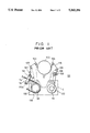
- FIG. 1 shows a tape loading mechanism of a so-called helical-scanning VCR wherein a tape is drawn from a cassette and is helically wound around a rotating head drum to perform a recording/reproducing operation.
- FIG. 1 there are shown a cassette C, a supply-side reel SR and a takeup-side reel TR.
- a rotating head drum 102 is rotatably mounted on the main chassis 101 in an inclined state at a predetermined angle, and is rotated at a high speed by a motor (not shown).
- Movable tape guide posts 103-106 draw a tape 116 from the cassette C mounted on the main chassis 101, and wind it around the rotating head drum 102 to form a tape path shown in FIG. 1.
- the movable tape guide posts 103-106 are operated by a well-known mechanism (not shown).
- a fixed guide post 107 for forming the tape path is provided on the main chassis 101.
- a capstan 108 drives the tape 116.
- a pinch roller 109 presses the tape 116 against the capstan 108 to run the tape 116.
- a supply-side reel mount 128 and a takeup-side reel mount 132 engage the supply-side reel SR and the takeup-side reel TR within the mounted cassette C to rotate the reels, respectively.
- These reel mounts 128 and 132 are rotatably driven by well-known means (not shown).
- a tension regulator arm (hereinafter termed a tension arm) 110 maintains the tension of the tape 116 running along the tape path at a constant value to provide good contact of the tape 116 with head drum 102.
- the tension arm 110 is rotatably disposed on the main chassis 101 via a pin 110a provided at one end of the tension arm 110.
- a pin 112 contacting the tape 116 is provided at the other end of the tension arm 110.
- the tension arm 110 is biased in a direction to press the pin 112 against the tape 116 by the elasticity of spring 114, and is connected to one end of a belt 130 wound around the outer circumference of the supply-side reel mount 128.
- the movable guide posts 103-106, the pinch roller 109 and the pin 112 of the tension arm 110 are situated inside the tape 116 within the cassette C, as indicated by broken lines in FIG. 1.
- the movable guide posts 103-106, the pinch roller 109 and the pin 112 of the tension arm 110 draw the tape 116 from within the cassette C to provide a loading state wherein the tape path shown in FIG. 1 is formed.
- the tape tension in a normal tape running state wherein the tape 116 runs in the direction of arrow A (the forward direction) shown in FIG. 1, the tape tension must be maintained constant.
- the tension arm 110 is free, and a change in the tape tension is detected to control the braking effect of the belt 130, as described above.
- the brake for the supply-side reel mount 128 is thereby controlled to maintain the tape tension constant.
- the tape 116 When the tape 116 stops, the tape 116 must be loosened because the tape 116 may be damaged if an unnecessary tension is applied to the tape 116.
- the tension arm 110 must free the tape 116 when the tape 116 is running in the forward direction, restrict the tape 116 at a position where the tape 116 is loosened when the tape 116 stops, and restrict the movement of the tape 116 due to an excessive tension when the tape 116 is running in the reverse direction so that the running position of the tape 116 is not changed by the rotation of the tension arm 110 due to an increase in the tension.
- the tension arm 110 is situated inside the tape 116 within the cassette C indicated by the broken lines in FIG. 1 in an unloading state, draws the tape 116 by rotating in the direction of arrow B in accordance with a tape loading operation, and is at the tape loading position shown in FIG. 1. Accordingly, it is impossible to provide means, such as a stopper or the like, for restricting the position of the tension arm 110 when the tape 116 stops or runs in the reverse direction, because such means obstructs the rotation of the tension arm 110.
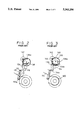
- FIGS. 2 and 3 shown an example of such configurations.
- the same components as shown in FIG. 1 are indicated by the same reference numerals.
- a stopper arm 134 is rotatably disposed on the main chassis 101 by a pin 136.
- a restricting member 134a for restricting the position of the tension arm 110 is formed at one end of the stopper arm 134.
- a cam follower pin 134a engaging a cam groove 138a formed on a gear board 138 (to be described later) is provided at the other end of the stopper arm 134.
- the cam board 138 functions as a mode control means for setting various kinds of operational modes including the tape loading mechanism shown in FIG. 1 via a well-known drive transmission mechanism (not shown), and is rotatably disposed on the main chassis 101 via a pin 140.
- a gear portion formed on the outer circumference of the cam board 138 meshes with gear 144 mounted on the rotation shaft of a motor 142, whereby the cam board 138 is rotated by the rotation of the motor 142 at a reduced speed.
- the cam groove 138a whose distance from the pin 140 serving as the center of rotation changes in accordance with the rotational position, is formed on the cam board 138 so as to control the rotation of the stopper arm 134 by the rotation of the cam board 138 via the cam groove 138a.
- FIG. 2 shows a state in the course of tape loading shifting from an unloading state to a tape loading state.
- the cam follower pin 134b of the stopper arm 134 moves along a small-diameter portion of the cam groove 138a during the unloading state and the tape loading operation, whereby the stopper arm 134 is rotated in a counterclockwise direction and the restricting member 134a is maintained at a position out of the rotational range of the tension arm 110. Accordingly, the rotation of the tension arm 110 during the tape loading operation is not obstructed.
- the cam follower pin 134b of the stopper arm 134 moves from the small-diameter portion to a large-diameter portion of the cam groove 138a, as shown in FIG. 3, to rotate the stopper arm 134 in a clockwise direction.
- the restricting member 134a is moved to a position where the rotation of the tension arm 134 can be restricted. It is thereby possible to restrict the rotational position of the tension arm 110 if an excessive tension is applied during, for example, a playback operation of the tape in the reverse direction.
- the tension arm 110 is driven in a counterclockwise direction by the spring 114 to press its pin 112 against the tape. Hence, the tension continues to be applied to the tape, causing damage to the tape as described above.
- a new stopper for restricting the tension arm 110 against the spring 114 is needed.
- Such a stopper must be separated from the tension arm 110 in its normal position because the stopper may obstruct the rotation of the tension arm 110 during the normal tape running state, and must be in close contact with the tension arm 110 only when the tape stops.
- the stopper cannot be provided within the rotational range of the tension arm 110.
- a tape tension adjusting device comprising an adjusting member in contact with a running tape, with the adjusting member including a pivoting pin for rotating in accordance with a tension applied by the tape.
- a restricting member restricts the rotation of the adjusting member when the tension applied by the tape is more than a predetermined value, and pressing means presses the adjusting member against the restricting member when the tape is not running.
- the tape tension adjusting device comprises a rotatably mounted adjusting member in contact with the running tape, with the adjusting member rotating about one end in accordance with a tension applied by the tape.
- a stationary restricting member restricts rotation of the adjusting member when the tension applied by the tape is more than a predetermined value.
- the tension arm, or adjusting member is restricted by the restricting member even if a tension applied is more than the predetermined value, for example, while the tape is running in the reverse direction, whereby the tension arm is prevented from being rotated more than necessary.
- the tape can be in a non-tensioned state by pressing the tension arm against the restricting member by the pressing means. Since it is only necessary to increase the positional accuracy of the restricting member, the production and assembly of the device can be easily performed, whereby the production cost can be reduced.
- FIG. 1 is a diagram showing a tape loading mechanism of a helical scanning VCR.
- FIG. 2 is a diagram showing a tension arm restricting method using a movable member in the prior art, and represents a case wherein a tape is running in the forward direction;
- FIG. 3 represents a case wherein a tape is running in the reverse direction in the method shown in FIG. 2;
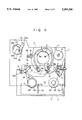
- FIG. 4 is a diagram showing an embodiment of the present invention, and represents a tape unloading state
- FIG. 5 represents a tape loading state in the embodiment shown in FIG. 4;
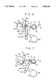
- FIG. 6 is a plan view of a tape tension adjusting device when a tape is running according to the embodiment.
- FIG. 7 is a plan view of the device when the tape stops.
- a tape tension adjusting device according to the preferred embodiment of the present invention will now be explained in detail. First, an outline of the embodiment will be briefly described.
- tape loading mechanisms configured such that, after loading a cassette at a loading position on a main chassis, the cassette itself is further slid to the side of a rotating head drum in accordance with a tape loading operation to provide a tape loading state wherein part of the rotating head drum is received in a recess formed at a front surface of the tape-drawing side of the cassette.
- a slide chassis which slides on the main chassis while mounting the cassette is disposed so as to be able to slide back and forth relative to the rotating head drum.
- a supply reel mounted, a takeup reel mount, a tension arm and the like are also disposed on the slide chassis.
- a fixed restricting member is provided at a position which is out of the rotational range of a tension arm in a tape unloading state wherein a slide chassis mounting a cassette is separated from a rotating head drum, and which is within the rotational range of the tension arm after the rotation of the tension arm to its operational position has been completed in a tape loading state wherein the slide chassis advances to the rotating head drum.
- the positional restriction of the tension arm in a plurality of operational modes is performed by pressing the tension arm against the fixed restricting member, thereby increasing positional accuracy.
- the tension arm can be restricted by the common fixed restricting member both when an excessive tension is applied and when the tension arm is forcively fixed in the case that the tape is not running.
- FIGS. 4 and 5 show a tape loading mechanism in a VCR.
- FIG. 4 represents a tape unloading state
- FIG. 5 represents a tape loading state.
- FIGS. 4 and 5 there is shown a main chassis 1.
- a rotating head drum 2 is rotatably mounted on the main chassis 1 in an inclined state at a predetermined angle via a drum base 3, and is configured so as to be rotated at a predetermined high speed by a drum motor (not shown).
- a tape-entrance-side movable guide post 4a draws a tape from within a cassette C and winds the tape around the rotating head drum 2 at a predetermined angle from a tape-entrance side in a tape loading operation, and is moved along a guide groove 3a formed in the drum base 3 by a driving system (to be described later).
- a tape-exit-side movable guide post 4b draws the tape from within the cassette C and winds the tape T around the rotating head drum 2 at the predetermined angel from a tape-exit side in a tape loading operation, and is moved along a guide groove 3b formed in the drum base 3 by a driving system (to be described later).
- a capstan 5 is rotated by a motor (not shown) to move the tape.
- a movable inclined guide post 4c is operatively linked with the tape-exit-side movable guide post 4b by a driving system (to be described later) to draws the tape and guide the tape to the capstan 5 (in the position shown in FIG. 5).
- the operational position of the inclined guide post 4c is positioned by a positioning member 1c.
- a fixed guide post 18, and a guide roller 6 which comprises an impedance roller are disposed in the main chassis 1.
- a positioning member 20 for positioning a tension arm (to be described later) is formed at a portion for mounting the fixed guide post 18 on the main chassis 1.
- a movable chassis (hereinafter termed a slide chassis) 7 is disposed so as to be slidable back and forth relative to the rotating head drum 2 on the main chassis 1 by means of long holes 7a and 7b in the slide chassis 7 and pins 1a and 1b on the main chassis 1.
- a cassette mounting unit 71 is formed on the upper surface of the slide chassis 7. In the unloading state shown in FIG. 4, the slide chassis 7 retracts from the rotating head drum 2 so that the cassette C can be detached. In a state wherein any of various kinds of operational modes can be adopted after the completion of tape loading as shown in FIG. 5, the slide chassis 7 advances to the rotating head drum 2 so that part of the rotating head drum 2 is received within a recess C1 in the front surface of the cassette C, whereby the space is reduced, and it becomes possible to provide a small device.
- a supply reel mount 28 and a takeup reel mount 32 are rotatably disposed on the slide chassis 7, engage a supply reel SR and a takeup reel TR of the mounted cassette C, respectively, and drive these reels in directions corresponding to the operational mode with a speed corresponding to the mode.
- These reel mounts are rotatably driven by a reel motor (not shown).
- a tension arm 10 is rotatably disposed on the slide chassis 7 via a pin 10a, is driven in a counterclockwise direction by a spring 14, detects the tape tension by pressing the tape 16 drawn from the supply reel SR against a tension post 12, and maintains the tape tension constant by a controlling brake applied from a belt 30 wound around the circumference of the supply reel mount 28.
- the configuration and operation of this portion will be described in detail later.
- a pinch roller lever 8 supports a pinch roller 8a pressed against the capstan 5 while receiving the tape 16 between the pinch roller 8a and the capstan 5 (see FIG. 5).
- a movable guide post 9 guides the tape 16 passing the capstan 5 to the takeup reel TR within the cassette C.
- a cam board (named a mode cam) 22 for mode control is rotatably disposed on the main chassis 1 via a pin 22a.
- the cam board 22 is rotated by a motor (not shown) to run the tape loading operation and the tape unloading operation by operating the slide chassis 7, the respective movable guide posts 4a-4c and 9, the pinch roller lever 8 and the tension arm 10 via drive transmission mechanisms (not shown).
- the cam board 22 also sets various kinds of operational modes (for example, recording, playback, quick-feeding, rewinding, high-speed search, still playback, slow playback, reverse playback, stop and the like) in the tape loading state.
- a cam groove 22b comprising a large-diameter portion and a small-diameter portion with respect to the center of rotation for controlling the rotation of a tension arm restricting lever 24 (to be described later) is formed on the upper surface of the cam board 22.
- tension arm restricting lever 24 is rotatably mounted on the main chassis 1 via a pin 241.
- a leaf spring 26 for restricting the position of the tension arm 10 by pressing the tension arm 10 against the mounting base 20 of the fixed guide post 18 in accordance with an operational mode is mounted on the other end of the tension arm restricting lever 24.
- a cam follower pin 24b engaging the cam groove 22b in the upper surface of the cam board 22 for mode switching is formed on the lower surface of the tension arm restricting lever 24.
- the tension arm restricting lever 24 is rotated by the cam groove 22b in accordance with the rotation of the cam board 22, and the position of the tension arm 10 is restricted in accordance with the operational mode of the tension arm restricting lever 24.
- the operation of the tension arm restricting lever 24 will be described in detail later.
- the tape loading mechanism in the present embodiment has the above-described configuration.
- the slide chassis 7 is separated from the rotating head drum 2 so that the chassis C can be mounted on a cassette mounting unit 71 of the slide chassis 7.
- the mounting base 20 of the fixed guide post 18 for restricting the position of the tension arm 10 is separated from the rotational range of the tension arm 10, and is in a positional relationship with the tension arm 10 so as not to obstruct the rotation of the tension arm 10 in a tape loading operation.
- a loading motor (not shown) rotates to start the rotation of the cam board 22 for mode switching.
- the slide chassis 7 mounting the cassette C thereby starts to advance via a drive transmission mechanism (not shown), the movable guide posts 4a-4c and 9, the pinch roller 8a, and the pin 12 of the tension arm 10 start to move outside the cassette C, and a tape loading operation for drawing the tape from within the cassette C and loading the tape to the rotating head drum 2 and the capstan 5 is started.
- the tape path shown in FIG. 5 is formed to provide a tape loading state.
- the cassette C on the slide chassis 7 is advanced to the rotating head drum 2, a state wherein part of the drum 2 is received within the recess C1 in the front surface of the cassette C is provided, and the tape loading state is thereby provided.
- the present embodiment is configured so that by the advancing sliding operation of the slide chassis 7, the mounting base 20 which is out of the rotational range of the tension arm 10 in the tape unloading state shown in FIG. 4 assumes a position within the rotational range of the tension arm 10 where the position of the tension arm 10 can be restricted, and the tension arm 10 is rotated to the position in the tape loading state shown in FIG. 5 by passing the tension arm 10 in front of the mounting base 20 before the mounting base 20 enters within the rotational range of the tension arm 10.
- the mounting base 20 in the tape loading state, as is apparent from FIG. 5, the mounting base 20 must be situated within the rotational range of the tension arm 10 because the mounting base 20 restricts movement of the tension arm 10. However, if the mounting base 20 is provided at such a position in a tape unloading state, the mounting base 20 obstructs the rotation of the tension arm 10, whereby it becomes impossible to perform a tape loading operation.
- the mounting base 20 formed on the main chassis 1 is situated outside the rotational range of the tension arm 10 until the tension arm 10 is rotated to the operational position in the tape loading state utilizing the sliding movement of the slide chassis 7, and the mounting base 20 is situated within the rotational range after the completion of the movement of the tension arm 10 to the operational position.
- the guide pin 12 is set on the distal end portion of the tension arm 10 rotatable around the pin 10a.
- the tension arm 10 is always biased in a counterclockwise direction by the spring 14.
- the tension arm 10 is at the position indicated by solid lines when the tape is running in the forward direction , and is at the position indicated by one-dot chain lines when the tape is running in the reverse direction.
- the magnetic tape 16 is drawn from the tape cassette.
- the guide post 18 guides the magnetic tape 16, and is fixed on the chassis 1 via the mounting base 20.
- the mounting base 20 is precisely positioned so as to restrict the rotation of the tension arm 10 in a clockwise direction due to the contact of the tension arm 10 with a side surface of the mounting base 20 when the tape is running in the reverse direction, as will be described in detail later.
- the cam groove 22b is formed in the cam board 22 rotatable around the shaft 22a.
- the lever 24 is rotatable around the pin 24a.
- the pin 24b set on a side surface of the lever 24 enters the cam groove 22b of the cam board 22, whereby the lever 24 rotates around the pin 24a in accordance with the rotation of the cam board 22.
- the leaf spring 26 is mounted on the distal end portion of the lever 24. The lever 24 and the leaf spring 26 are provided in a position so as to release the tension arm 10 when the tape 16 is running, as shown in FIG. 6, and to force the tension arm 10 to contact the mounting base 20 when the tape is not running, as shown in FIG. 7.
- the tension belt 30, one end of which is fixed on the main chassis 1, is fixed on the tension arm 12 while being wound around the reel mount 28.
- the tension arm 10 when the tape is running in the reverse direction, the tension arm 10 is restricted by the mounting base 20 which is precisely positioned. Hence, accuracy in the restricting position of the guide pin 12 determining the path of the tape can be easily obtained.
- the tape When the tape is not running, it is only necessary to press the tension arm 10 against the mounting base 20 by the leaf spring 26. Hence, high accuracy is not required for the components, and it is only necessary to use simple components.
- the mounting base 20 for the guide post 18 is used for restricting the rotation of the tension arm 10
- any other member fixed to the main chassis 1, the guide post 18 itself or the main chassis 1 itself may of course by used in place of the mounting base 20.
- any other elastic member may be used in place of the leaf spring 26.
- the lever 24 may be driven by a solenoid.
- the position restriction of the tension arm in the plurality of operational modes is performed by pressing the tension arm against the common fixed member to improve positional accuracy, and the tension arm can be restricted by the common fixed member both when an excessive tension is applied and when the tension arm is forcively fixed when the tape is not running. Furthermore, it is possible to provide a high-precision fixed positioning means without obstructing the operation of the tension arm, and to precisely restrict tape tension and a tape position.
Landscapes
- Registering, Tensioning, Guiding Webs, And Rollers Therefor (AREA)
Priority Applications (1)
| Application Number | Priority Date | Filing Date | Title |
|---|---|---|---|
| US08/237,103 US5448431A (en) | 1990-12-06 | 1994-05-03 | Tape tension adjusting device including a movable chassis carrying a rotatable arm which is adapted to engage a stop pin on a stationary chassis |
Applications Claiming Priority (2)
| Application Number | Priority Date | Filing Date | Title |
|---|---|---|---|
| JP2400569A JP2993522B2 (ja) | 1990-12-06 | 1990-12-06 | テープ・テンション調節装置及び記録再生装置 |
| JP2-400569 | 1990-12-06 |
Related Child Applications (1)
| Application Number | Title | Priority Date | Filing Date |
|---|---|---|---|
| US08/237,103 Continuation US5448431A (en) | 1990-12-06 | 1994-05-03 | Tape tension adjusting device including a movable chassis carrying a rotatable arm which is adapted to engage a stop pin on a stationary chassis |
Publications (1)
| Publication Number | Publication Date |
|---|---|
| US5363256A true US5363256A (en) | 1994-11-08 |
Family
ID=18510467
Family Applications (2)
| Application Number | Title | Priority Date | Filing Date |
|---|---|---|---|
| US07/802,212 Expired - Lifetime US5363256A (en) | 1990-12-06 | 1991-12-04 | Tape tension adjusting device |
| US08/237,103 Expired - Lifetime US5448431A (en) | 1990-12-06 | 1994-05-03 | Tape tension adjusting device including a movable chassis carrying a rotatable arm which is adapted to engage a stop pin on a stationary chassis |
Family Applications After (1)
| Application Number | Title | Priority Date | Filing Date |
|---|---|---|---|
| US08/237,103 Expired - Lifetime US5448431A (en) | 1990-12-06 | 1994-05-03 | Tape tension adjusting device including a movable chassis carrying a rotatable arm which is adapted to engage a stop pin on a stationary chassis |
Country Status (2)
| Country | Link |
|---|---|
| US (2) | US5363256A (ja) |
| JP (1) | JP2993522B2 (ja) |
Cited By (7)
| Publication number | Priority date | Publication date | Assignee | Title |
|---|---|---|---|---|
| US5543980A (en) * | 1992-03-16 | 1996-08-06 | Canon Kabushiki Kaisha | Tape loading device having an urging element for urging a tape tension detecting arm after a predetermined rotation of a driving member |
| US5808827A (en) * | 1994-11-09 | 1998-09-15 | Sony Corporation | Tape loading mechanism |
| US5923495A (en) * | 1994-12-28 | 1999-07-13 | Canon Kabushiki Kaisha | Recording and/or reproducing apparatus with control mechanism for controlling movement of tape guide members |
| US20020122270A1 (en) * | 2001-01-29 | 2002-09-05 | Yasuaki Kano | Tape drive |
| US6654199B1 (en) * | 1999-11-08 | 2003-11-25 | Canon Kabushiki Kaisha | Recording/reproducing apparatus with reduced number of guide posts |
| EP1400965A3 (en) * | 2002-10-12 | 2007-02-28 | Samsung Electronics Co., Ltd. | Cassette tape deck |
| US7255297B2 (en) | 2004-06-04 | 2007-08-14 | Quantum Corporation | Adaptive tape drive roller guide |
Families Citing this family (7)
| Publication number | Priority date | Publication date | Assignee | Title |
|---|---|---|---|---|
| KR200141228Y1 (ko) * | 1995-03-28 | 1999-04-15 | 구자홍 | 자기기록재생기의 테이프 걸림방지 및 진동흡수장치 |
| US5776025A (en) * | 1996-09-25 | 1998-07-07 | Eastman Kodak Company | Adjustable self-aligning belt tensioner |
| EP0837466B1 (en) * | 1996-10-15 | 2004-12-22 | Hewlett-Packard Company, A Delaware Corporation | Tape drives for use with tape cartridges |
| DE10118874A1 (de) * | 2001-04-18 | 2002-10-24 | Ina Schaeffler Kg | Arretiervorrichtung für zueinander bewegliche Maschinenteile |
| JP2004288236A (ja) * | 2003-03-19 | 2004-10-14 | Matsushita Electric Ind Co Ltd | 磁気記録再生装置 |
| US7071908B2 (en) * | 2003-05-20 | 2006-07-04 | Kagutech, Ltd. | Digital backplane |
| US7422385B2 (en) * | 2004-11-30 | 2008-09-09 | Kabushiki Kaisha Sato | Printing paper winding device |
Citations (2)
| Publication number | Priority date | Publication date | Assignee | Title |
|---|---|---|---|---|
| US5031056A (en) * | 1987-11-09 | 1991-07-09 | Clarion Co., Ltd. | Tape tension mechanism |
| US5159506A (en) * | 1989-12-25 | 1992-10-27 | Victor Company Of Japan, Ltd. | Magnetic tape recording/reproducing apparatus with improved tension control mechanism |
Family Cites Families (2)
| Publication number | Priority date | Publication date | Assignee | Title |
|---|---|---|---|---|
| KR910010165B1 (ko) * | 1987-05-13 | 1991-12-17 | 마쯔시다덴기산교 가부시기가이샤 | 자기기록 재생장치 |
| JP3123129B2 (ja) * | 1991-06-28 | 2001-01-09 | ソニー株式会社 | テープテンション調整機構 |
-
1990
- 1990-12-06 JP JP2400569A patent/JP2993522B2/ja not_active Expired - Lifetime
-
1991
- 1991-12-04 US US07/802,212 patent/US5363256A/en not_active Expired - Lifetime
-
1994
- 1994-05-03 US US08/237,103 patent/US5448431A/en not_active Expired - Lifetime
Patent Citations (2)
| Publication number | Priority date | Publication date | Assignee | Title |
|---|---|---|---|---|
| US5031056A (en) * | 1987-11-09 | 1991-07-09 | Clarion Co., Ltd. | Tape tension mechanism |
| US5159506A (en) * | 1989-12-25 | 1992-10-27 | Victor Company Of Japan, Ltd. | Magnetic tape recording/reproducing apparatus with improved tension control mechanism |
Cited By (10)
| Publication number | Priority date | Publication date | Assignee | Title |
|---|---|---|---|---|
| US5543980A (en) * | 1992-03-16 | 1996-08-06 | Canon Kabushiki Kaisha | Tape loading device having an urging element for urging a tape tension detecting arm after a predetermined rotation of a driving member |
| US5808827A (en) * | 1994-11-09 | 1998-09-15 | Sony Corporation | Tape loading mechanism |
| CN1118807C (zh) * | 1994-11-09 | 2003-08-20 | 索尼公司 | 装带机构 |
| US5923495A (en) * | 1994-12-28 | 1999-07-13 | Canon Kabushiki Kaisha | Recording and/or reproducing apparatus with control mechanism for controlling movement of tape guide members |
| US6654199B1 (en) * | 1999-11-08 | 2003-11-25 | Canon Kabushiki Kaisha | Recording/reproducing apparatus with reduced number of guide posts |
| US7057846B2 (en) | 1999-11-08 | 2006-06-06 | Canon Kabushiki Kaisha | Recording/reproducing apparatus with reduced number of guides posts |
| US20020122270A1 (en) * | 2001-01-29 | 2002-09-05 | Yasuaki Kano | Tape drive |
| US6762903B2 (en) * | 2001-01-29 | 2004-07-13 | Sony Corporation | Tape drive |
| EP1400965A3 (en) * | 2002-10-12 | 2007-02-28 | Samsung Electronics Co., Ltd. | Cassette tape deck |
| US7255297B2 (en) | 2004-06-04 | 2007-08-14 | Quantum Corporation | Adaptive tape drive roller guide |
Also Published As
| Publication number | Publication date |
|---|---|
| US5448431A (en) | 1995-09-05 |
| JP2993522B2 (ja) | 1999-12-20 |
| JPH04209351A (ja) | 1992-07-30 |
Similar Documents
| Publication | Publication Date | Title |
|---|---|---|
| US5363256A (en) | Tape tension adjusting device | |
| GB2071900A (en) | Magnetic tape recording and/or reproducing apparatus | |
| EP0628961B1 (en) | A tape tensioning mechanism | |
| US4510534A (en) | Still-mode magnetic reproducing device | |
| US6256167B1 (en) | Magnetic recording/reproduction apparatus having a mechanism for pulling a magnetic tape out of a cassette | |
| KR100317597B1 (ko) | 자기 기록/재생 장치 | |
| US5333807A (en) | Recording and reproducing apparatus having a tape tension changing mechanism | |
| US6215612B1 (en) | Magnetic recording/reproduction apparatus having a rotary head cylinder and a mechanism for passing a magnetic tape around the rotary head cylinder for a predetermined arc | |
| JP2501781Y2 (ja) | テ―プガイド機構 | |
| US6172840B1 (en) | Magnetic recording/reproduction apparatus including a rotary head cylinder and both vertical and inclined guides for winding a magnetic tape about the rotary head cylinder | |
| JP2954739B2 (ja) | 磁気記録再生装置のカム操作機構 | |
| US5991116A (en) | Mechanism for drawing out tape | |
| KR100277153B1 (ko) | 릴대의 후방 장력 기구 | |
| JPH056580Y2 (ja) | ||
| KR0113203Y1 (ko) | 자기기록재생기의 테이프 고속 주행장치 | |
| US6404583B1 (en) | Magnetic tape recording/reproducing apparatus | |
| JPH0430676Y2 (ja) | ||
| JPH0421262B2 (ja) | ||
| JPH03295052A (ja) | ピンチローラの圧着機構 | |
| KR20020014905A (ko) | 테이프 레코더의 테이프 장력 조절장치 | |
| JPS59215065A (ja) | 回転ヘツド型記録または再生装置 | |
| JPH1011842A (ja) | 磁気記録再生装置 | |
| JPH04271051A (ja) | テープレコーダ装置 | |
| JPS62200558A (ja) | 磁気記録再生装置 | |
| JPS61151862A (ja) | 回転ヘツド型磁気記録再生装置 |
Legal Events
| Date | Code | Title | Description |
|---|---|---|---|
| AS | Assignment |
Owner name: CANON KABUSHIKI KAISHA, JAPAN Free format text: ASSIGNMENT OF ASSIGNORS INTEREST.;ASSIGNOR:KOBAYASHI, JUNI;REEL/FRAME:006005/0866 Effective date: 19920113 |
|
| STCF | Information on status: patent grant |
Free format text: PATENTED CASE |
|
| CC | Certificate of correction | ||
| FPAY | Fee payment |
Year of fee payment: 4 |
|
| FEPP | Fee payment procedure |
Free format text: PAYER NUMBER DE-ASSIGNED (ORIGINAL EVENT CODE: RMPN); ENTITY STATUS OF PATENT OWNER: LARGE ENTITY Free format text: PAYOR NUMBER ASSIGNED (ORIGINAL EVENT CODE: ASPN); ENTITY STATUS OF PATENT OWNER: LARGE ENTITY |
|
| FPAY | Fee payment |
Year of fee payment: 8 |
|
| FPAY | Fee payment |
Year of fee payment: 12 |