US5688106A - Turbomolecular pump - Google Patents
Turbomolecular pump Download PDFInfo
- Publication number
- US5688106A US5688106A US08/748,526 US74852696A US5688106A US 5688106 A US5688106 A US 5688106A US 74852696 A US74852696 A US 74852696A US 5688106 A US5688106 A US 5688106A
- Authority
- US
- United States
- Prior art keywords
- pumping
- plate
- stator
- spiral
- rotor
- Prior art date
- Legal status (The legal status is an assumption and is not a legal conclusion. Google has not performed a legal analysis and makes no representation as to the accuracy of the status listed.)
- Expired - Fee Related
Links
Images


Classifications
-
- F—MECHANICAL ENGINEERING; LIGHTING; HEATING; WEAPONS; BLASTING
- F04—POSITIVE - DISPLACEMENT MACHINES FOR LIQUIDS; PUMPS FOR LIQUIDS OR ELASTIC FLUIDS
- F04D—NON-POSITIVE-DISPLACEMENT PUMPS
- F04D17/00—Radial-flow pumps, e.g. centrifugal pumps; Helico-centrifugal pumps
- F04D17/08—Centrifugal pumps
- F04D17/16—Centrifugal pumps for displacing without appreciable compression
- F04D17/168—Pumps specially adapted to produce a vacuum
-
- F—MECHANICAL ENGINEERING; LIGHTING; HEATING; WEAPONS; BLASTING
- F04—POSITIVE - DISPLACEMENT MACHINES FOR LIQUIDS; PUMPS FOR LIQUIDS OR ELASTIC FLUIDS
- F04D—NON-POSITIVE-DISPLACEMENT PUMPS
- F04D19/00—Axial-flow pumps
- F04D19/02—Multi-stage pumps
- F04D19/04—Multi-stage pumps specially adapted to the production of a high vacuum, e.g. molecular pumps
- F04D19/046—Combinations of two or more different types of pumps
Definitions
- the present invention relates to turbomolecular pumps. More particularly, the invention refers to a turbomolecular vacuum pump provided with pumping stages with a high compression ratio, of the type used in the manufacturing of semiconductor devices.
- Turbomolecular vacuum pumps have been widely used in the manufacturing of semiconductor devices since the introduction of dry etching methods in the manufacturing of integrated circuits (IC) or chips.
- FIG. 1 is a schematic view showing a longitudinal cross section of a conventional turbo-molecular pump 1' equipped with a first assembly 56a' of pumping stages having stators 5a' and rotor disks with blades 6a', and a second assembly 56b' of pumping stages having stators 5b' smooth rotor disks 6b'.
- FIG. 1 the arrows schematically show the path of an inert gas, admitted under pressure through a radial hole 16' into the gaps between the motor assembly 10' and the pump body 2', and directed towards the bearing 8'.
- a circular plate 11' separating the bearing 8' from the second pumping assembly 56b' of pumping stages having smooth rotor disks 6b', is provided with three radial channels 14' angularly spaced at 120° from each other and communicating with as many axial holes 17', provided in the body 2' of the pump 1' and the motor assembly 10'.
- said channels 14' communicate with the openings or ports existing between the body 2' of the pump 1' and the motor assembly 10'.
- this solution still has a number of drawbacks.
- FIG. 2 shows a schematic turbomolecular pump with inverted dynamic seal.
- the inverted dynamic seal substantially comprises screw 101 located inside cylindrical chamber 102 having a smooth wall and formed in body 103 of the rotor assembly 100 of the pump.
- the rotating motion, and the reduced gap between the walls of chamber 102 and screw 101 generate a pressure difference that can be used to achieve the so-called "inverted dynamic seal” as well as for pumping the gas.
- the obtained sealing is implemented in a turbomolecular pump 100, and is used for pumping the gas into the space housing bearings 105.
- the turbomolecular pump with inverted dynamic seal presents a number of drawbacks. Firstly, the inverted dynamic seal is poorly effective when the gases to be pumped are lighter than Ar (40), e.g. HF (20), HCl (36), and for low flow rate of the gases to be pumped.
- Ar e.g. HF (20), HCl (36)
- the inverted dynamic seal is not suitable for applications wherein the input pressures are higher than 10 -2 Pa, that is for high pumping flow rates, when on the contrary a maximum protection against corrosive gases would be required. Moreover, it is difficult to manufacture the screw of the inverted dynamic seal which is located within the chamber housing the bearings.
- turbomolecular pumps provided with spiral-shaped pumping stages of the so-called Siegbahn type.
- Such pumps have only been realized in a single-stage configuration with the gas pumping occurring exclusively within the spirally-shaped channel, and no gas pumping would be possible without this channel.
- the main object of the present invention is to provide a turbomolecular pump equipped with a dynamic seal that achieves the advantages of the known solutions, while at the same time avoiding the drawbacks thereof.
- Another object of the present invention is to provide a turbomolecular pump having pumping stages with a high compression ratio.
- a further object of the present invention is to provide a dynamic seal that is easy and economical to be manufactured.
- a turbomolecular pump with a pump body having a gas inlet port and gas exhaust port; and a plurality of vacuum pumping stages located therewith and disposed between the inlet port and exhaust port.
- Each pumping stage comprises a rotor and a stator with a pair of faces wherein at least one stator has at least one spiral channel formed on one of the faces of the stator.
- the turbomolecular pump also comprises a rotating shaft for securing each rotor thereto, which is held by at least one support means.
- a plate is positioned between the support means and the pumping stage proximate thereto.
- the plate has at least one spiral channel formed on a surface facing said proximate pumping stage for pushing and ejecting gases contained in the channel from an area proximal to the shaft to an area distal therefrom.
- the pump body further comprises at least one axial hole in proximity to said plate, and said plate further comprises at least one radial channel which is in communication with said axial hole for admitting inert gases in a space between the plate and the rotor of the proximate pumping stage and forming a spiral seal with the spiral channel.
- the plate has four spiral channels extending in identical directions.
- one or more pumping stages of the turbomolecular pump are located in proximity to the inlet port comprising rotors with blades and form a first pumping assembly, while one or more pumping stages are located in proximity to the exhaust port comprising rotors with flat disks and form a second pumping assembly, wherein at least one stator of the second pumping assembly comprises at least one spiral channel on each or at least one face thereof.
- FIG. 1 is a schematic cross section view of a turbomolecular pump of the prior art.
- FIG. 2 is a schematic cross section view of a turbomolecular pump incorporating an inverted dynamic seal of the prior art.
- FIG. 3 is a cross section view of a turbomolecular Pump according to the present invention.
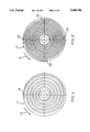
- FIG. 4 is a plan view of the plate in which a spiral seal with a single channel is formed.
- FIG. 5 is a plan view of the plate in which a spiral seal with four channels is formed.
- FIG. 6 is a plan view of the plate, as seen from the opposite side of that of FIGS. 4 or 5.
- FIG. 7 is a cross section view of one of the stators of the pump shown in FIG. 3.
- FIG. 8 is a plan view of the stator shown in FIG. 7.
- FIG. 9 is a plan view from the opposite side in respect to that shown in FIG. 8 of the stator of FIG. 7.
- the turbomolecular pump 1 of the present invention comprises a substantially cylindrical pump body 2 provided with axial inlet port 3 and radial exhaust port 4 for the gases.
- first pumping assembly 56a formed by a plurality of stators 5a and rotors 6a, these latter being provided with blades, with the stators and rotors being coplanar (i.e. substantially laying in a same plane) and alternating with each other.
- Each pair of respective stator and rotor of the plurality of stators 5a and rotors 6a forms a pumping stage.
- a second pumping assembly 56b formed by a plurality of stators 5b and rotors 6b that are smooth (i.e. without blades), coplanar and alternating with each other are fitted within pump body 2, near exhaust port 4, and axially aligned with said first pumping assembly 56a.
- Each pair of respective stator and rotor of the plurality of stators 5b and rotors 6b forms a pumping stage.
- Rotors 6a and 6b are secured to rotating shaft 7, which is supported by a pair of bearings 8 and 9 with motor assembly 10 located therebetween.
- Circular plate 11 is provided between bearing 8 and second pumping assembly 56b, and spiral channel 12 is formed in the plate surface facing first rotor 6b of pumping assembly 56b.
- spiral channel 12 is designed so that when rotors 6a and 6b rotate in the direction of arrow 13, the gases contained in the channel are pushed and ejected from the area proximal to shaft 7 towards an area distal therefrom. This way spiral channel 12 forms an effective pumping stage with its own characteristic compression ratio and pumping speed.
- circular plate 11 is also provided with three radial channels 14, located at 120° with respect of each other, and each radial channel communicating with one of three axial holes 17 in pump body 2 that open into space 15 housing motor 10.
- a radial hole 16 passes through the pump body 2 and allows the admission of an inert gas into space 15.
- the inert gas flows from space 15 through axial holes 17 and radial channels 14 into the gap between plate 11 and adjacent rotor 6b on which a spiral seal is formed by spiral channel 12. Due to the pumping action produced by spiral channel 12 and the action of the inert gas present in correspondence of plate 11 within spiral channel 12, the corrosive gases are pushed away from bearing 8 and ejected towards gas exhaust port 4 of pump 1.
- FIG. 5 illustrates another embodiment of the spiral sealing of the present invention in which the spiral sealing formed on the surface of the plate 21 comprises four spiral channels 20 extending in the same direction.
- the spiral sealing formed on the surface of the plate 21 comprises four spiral channels 20 extending in the same direction.
- stator 5b of second pumping assembly 56b which is proximal to plate 11, may be provided with at least one spiral channel formed on a surface facing plate 11 for pumping gases inwardly towards shaft 7, while a plurality of channels are formed on the opposite surface of stator 5b for pumping gases outwardly from shaft 7.
- one of the stators 5b is provided with a double spiral sealing each cooperating with the corresponding adjacent rotor 6b.
- the double spiral sealing is obtained by means of single spiral channel 18 located on a face of stator 5b, and by means of four spiral channels 19, located on the opposite face of adjacent stator 5b.
- Channels 18 and 19 are oriented in such a manner as to generate a counter-pumping effect with respect to the pumping flow generated by the pumping stage, such counter-pumping contrasting the natural movement of the escaping gas molecules towards the stages with higher pressure, through the ports located between the plane of rotor disks 6b and the plane of stator disks 5b.
- FIGS. 8 and 9 illustrate the spiral orientation with respect to motion of the rotor disk, with the rotating direction indicated by arrow 13. In this way, an outwardly directed pumping of the gases is achieved, thus increasing the sealing of the pumping stages and their compression ratio.
- the choice between the configuration with a single channel 18 and that with four channels 19 is based upon the fact that the sealing results of the single spiral channel are better at low pressures, typically about 10 -1 Pa, while the four channels sealing presents better results at high pressures, typically about 10 Pa, that should be present in proximity of the gas exhaust port of the pump.
- the spiral sealing looks similar to the one known as labyrinth sealing, their functions in the turbomolecular pump differ dramatically.
- the object of a labyrinth sealing is to geometrically increase the length of the interstitial paths between the static and rotating parts of the turbomachines to reduce the conductances, and therefore the losses due to blow-by.
- the labyrinth sealings are "static" devices since they do not use the rotation of moving parts for achieving the sealing effect, but only use the geometrical effect of a path increase.
- the spiral sealing of the present invention besides contributing to geometrically increase the length of the escaping ways, dynamically operates by pumping away the gas which tends to enter the ducts.
- Yet another embodiment of the present invention provides for reversing the orientation of the single spiral channel, or the four spiral channels, in respect to what was previously described and shown in the embodiments.
- the spiral channel or channels are incoming in respect of the rotation of the rotor disc, and the channel inlets are located in correspondence of the outlets of the pumping channels in the pumping assembly, there is achieved a pumping effect with the same direction of the pumping stage with smooth rotors.
- a preferred embodiment particularly suitable in presence of corrosive gases, provides for arranging three spiral seals in series, positioned as illustrated in FIG. 3, with the first one having a single channel and pumping outwardly, formed on the surface of plate 11 facing rotor 6b; the second one, having a single channel and pumping inwardly, formed on the surface of stator 5b facing the plate 11; and the third one, having four channels and pumping outwardly, formed on the other face of same stator 5b.
- the sealing obtained through the present invention when the pump sizes are equal, advantageously operates at higher peripheral speeds, typically 200 m/see instead of 70 m/see, being formed on a plane rather than on a cylinder located within the rotors. While the invention has been described with reference to specific embodiments, the description is illustrative of the invention and is not to be construed as limiting the various modifications and applications which may occur to those skilled in the art without departing from the true spirit of the invention as defined by the appended claims.
Landscapes
- Engineering & Computer Science (AREA)
- Mechanical Engineering (AREA)
- General Engineering & Computer Science (AREA)
- Non-Positive Displacement Air Blowers (AREA)
- Structures Of Non-Positive Displacement Pumps (AREA)
Applications Claiming Priority (2)
| Application Number | Priority Date | Filing Date | Title |
|---|---|---|---|
| IT95TO000911A IT1281025B1 (it) | 1995-11-10 | 1995-11-10 | Pompa turbomolecolare. |
| ITT95A00911 | 1995-11-10 |
Publications (1)
| Publication Number | Publication Date |
|---|---|
| US5688106A true US5688106A (en) | 1997-11-18 |
Family
ID=11413956
Family Applications (1)
| Application Number | Title | Priority Date | Filing Date |
|---|---|---|---|
| US08/748,526 Expired - Fee Related US5688106A (en) | 1995-11-10 | 1996-11-08 | Turbomolecular pump |
Country Status (5)
| Country | Link |
|---|---|
| US (1) | US5688106A (2) |
| EP (1) | EP0773367B1 (2) |
| JP (1) | JPH09170589A (2) |
| DE (2) | DE773367T1 (2) |
| IT (1) | IT1281025B1 (2) |
Cited By (20)
| Publication number | Priority date | Publication date | Assignee | Title |
|---|---|---|---|---|
| US5848873A (en) * | 1996-05-03 | 1998-12-15 | The Boc Group Plc | Vacuum pumps |
| US6224326B1 (en) * | 1998-09-10 | 2001-05-01 | Alcatel | Method and apparatus for preventing deposits from forming in a turbomolecular pump having magnetic or gas bearings |
| US6290457B1 (en) * | 1999-03-31 | 2001-09-18 | Seiko Instruments Inc. | Vacuum pump |
| US6328527B1 (en) * | 1999-01-08 | 2001-12-11 | Fantom Technologies Inc. | Prandtl layer turbine |
| US6355109B2 (en) * | 1998-12-11 | 2002-03-12 | Tokyo Electron Limited | Vacuum processing apparatus |
| US6371735B1 (en) * | 1999-09-16 | 2002-04-16 | The Boc Group Plc | Vacuum pumps |
| US6409468B1 (en) * | 1998-06-30 | 2002-06-25 | Ebara Corporation | Turbo-molecular pump |
| US6412173B1 (en) | 1999-07-26 | 2002-07-02 | Phoenix Analysis And Design Technologies, Inc. | Miniature turbomolecular pump |
| US6468030B2 (en) * | 2000-06-23 | 2002-10-22 | Ebara Corporation | Turbo-molecular pump |
| US6499973B2 (en) * | 1997-10-03 | 2002-12-31 | Seiko Instruments Inc. | Turbo molecular pump |
| US6508631B1 (en) | 1999-11-18 | 2003-01-21 | Mks Instruments, Inc. | Radial flow turbomolecular vacuum pump |
| US6585480B2 (en) * | 1999-03-23 | 2003-07-01 | Ebara Corporation | Turbo-molecular pump |
| US20060018772A1 (en) * | 2004-07-20 | 2006-01-26 | Fausto Casaro | Rotary vacuum pump, structure and method for the balancing thereof |
| US20100158667A1 (en) * | 2008-12-24 | 2010-06-24 | Helmer John C | Centripetal pumping stage and vacuum pump incorporating such pumping stage |
| US20100158672A1 (en) * | 2008-12-24 | 2010-06-24 | Helmer John C | Spiral pumping stage and vacuum pump incorporating such pumping stage |
| US20140205433A1 (en) * | 2013-01-22 | 2014-07-24 | Agilent Technologies, Inc. | Spiral pumping stage and vacuum pump incorporating such pumping stage |
| IT201700075054A1 (it) * | 2017-07-04 | 2017-10-04 | Agilent Tech Inc A Delaware Corporation | Stadio di pompaggio molecolare per pompa da vuoto e pompa da vuoto comprendente detto stadio di pompaggio molecolare |
| US9909592B2 (en) | 2013-07-15 | 2018-03-06 | Pfeiffer Vacuum Gmbh | Vacuum pump |
| CN109441875A (zh) * | 2018-12-25 | 2019-03-08 | 大连金刚科技有限责任公司 | 叶轮及气体泵 |
| US10337517B2 (en) | 2012-01-27 | 2019-07-02 | Edwards Limited | Gas transfer vacuum pump |
Families Citing this family (4)
| Publication number | Priority date | Publication date | Assignee | Title |
|---|---|---|---|---|
| US20080056886A1 (en) * | 2006-08-31 | 2008-03-06 | Varian, S.P.A. | Vacuum pumps with improved pumping channel cross sections |
| GB0618745D0 (en) * | 2006-09-22 | 2006-11-01 | Boc Group Plc | Molecular drag pumping mechanism |
| EP2096317B1 (en) | 2008-02-27 | 2012-08-15 | Agilent Technologies, Inc. | Method for manufacturing the rotor assembly of a rotating vacuum pump |
| DE102013220879A1 (de) * | 2013-10-15 | 2015-04-16 | Pfeiffer Vacuum Gmbh | Vakuumpumpe |
Citations (5)
| Publication number | Priority date | Publication date | Assignee | Title |
|---|---|---|---|---|
| US4655678A (en) * | 1984-02-24 | 1987-04-07 | Seiko Seiki Kabushiki Kaisha | Combined turbo-molecular pump |
| JPS63255596A (ja) * | 1987-04-13 | 1988-10-21 | Ebara Corp | タ−ボ分子ポンプ |
| US5238362A (en) * | 1990-03-09 | 1993-08-24 | Varian Associates, Inc. | Turbomolecular pump |
| US5358373A (en) * | 1992-04-29 | 1994-10-25 | Varian Associates, Inc. | High performance turbomolecular vacuum pumps |
| US5547338A (en) * | 1994-03-26 | 1996-08-20 | Balzers-Pfeiffer Gmbh | Friction pump with magnetic bearings disposed in the impeller |
Family Cites Families (4)
| Publication number | Priority date | Publication date | Assignee | Title |
|---|---|---|---|---|
| US3969039A (en) * | 1974-08-01 | 1976-07-13 | American Optical Corporation | Vacuum pump |
| US4732529A (en) * | 1984-02-29 | 1988-03-22 | Shimadzu Corporation | Turbomolecular pump |
| EP0408791B1 (de) * | 1989-07-20 | 1994-03-16 | Leybold Aktiengesellschaft | Reibungspumpe mit glockenförmigem Rotor |
| DE4314418A1 (de) * | 1993-05-03 | 1994-11-10 | Leybold Ag | Reibungsvakuumpumpe mit unterschiedlich gestalteten Pumpenabschnitten |
-
1995
- 1995-11-10 IT IT95TO000911A patent/IT1281025B1/it active IP Right Grant
-
1996
- 1996-01-24 EP EP96200164A patent/EP0773367B1/en not_active Expired - Lifetime
- 1996-01-24 DE DE0773367T patent/DE773367T1/de active Pending
- 1996-01-24 DE DE69600306T patent/DE69600306T2/de not_active Expired - Lifetime
- 1996-11-08 US US08/748,526 patent/US5688106A/en not_active Expired - Fee Related
- 1996-11-11 JP JP8312612A patent/JPH09170589A/ja active Pending
Patent Citations (5)
| Publication number | Priority date | Publication date | Assignee | Title |
|---|---|---|---|---|
| US4655678A (en) * | 1984-02-24 | 1987-04-07 | Seiko Seiki Kabushiki Kaisha | Combined turbo-molecular pump |
| JPS63255596A (ja) * | 1987-04-13 | 1988-10-21 | Ebara Corp | タ−ボ分子ポンプ |
| US5238362A (en) * | 1990-03-09 | 1993-08-24 | Varian Associates, Inc. | Turbomolecular pump |
| US5358373A (en) * | 1992-04-29 | 1994-10-25 | Varian Associates, Inc. | High performance turbomolecular vacuum pumps |
| US5547338A (en) * | 1994-03-26 | 1996-08-20 | Balzers-Pfeiffer Gmbh | Friction pump with magnetic bearings disposed in the impeller |
Cited By (29)
| Publication number | Priority date | Publication date | Assignee | Title |
|---|---|---|---|---|
| US5848873A (en) * | 1996-05-03 | 1998-12-15 | The Boc Group Plc | Vacuum pumps |
| US6499973B2 (en) * | 1997-10-03 | 2002-12-31 | Seiko Instruments Inc. | Turbo molecular pump |
| US6409468B1 (en) * | 1998-06-30 | 2002-06-25 | Ebara Corporation | Turbo-molecular pump |
| US6224326B1 (en) * | 1998-09-10 | 2001-05-01 | Alcatel | Method and apparatus for preventing deposits from forming in a turbomolecular pump having magnetic or gas bearings |
| US6702899B2 (en) | 1998-12-11 | 2004-03-09 | Tokyo Electron Limited | Vacuum processing apparatus |
| US6355109B2 (en) * | 1998-12-11 | 2002-03-12 | Tokyo Electron Limited | Vacuum processing apparatus |
| US6328527B1 (en) * | 1999-01-08 | 2001-12-11 | Fantom Technologies Inc. | Prandtl layer turbine |
| US6585480B2 (en) * | 1999-03-23 | 2003-07-01 | Ebara Corporation | Turbo-molecular pump |
| US6290457B1 (en) * | 1999-03-31 | 2001-09-18 | Seiko Instruments Inc. | Vacuum pump |
| US6412173B1 (en) | 1999-07-26 | 2002-07-02 | Phoenix Analysis And Design Technologies, Inc. | Miniature turbomolecular pump |
| US6371735B1 (en) * | 1999-09-16 | 2002-04-16 | The Boc Group Plc | Vacuum pumps |
| US6508631B1 (en) | 1999-11-18 | 2003-01-21 | Mks Instruments, Inc. | Radial flow turbomolecular vacuum pump |
| EP2053250A3 (en) * | 2000-06-23 | 2009-07-15 | Ebara Corporation | Turbo-molecular pump |
| EP2284400A1 (en) * | 2000-06-23 | 2011-02-16 | Ebara Corporation | Turbo-molecular pump |
| US6468030B2 (en) * | 2000-06-23 | 2002-10-22 | Ebara Corporation | Turbo-molecular pump |
| US20060018772A1 (en) * | 2004-07-20 | 2006-01-26 | Fausto Casaro | Rotary vacuum pump, structure and method for the balancing thereof |
| US8152442B2 (en) | 2008-12-24 | 2012-04-10 | Agilent Technologies, Inc. | Centripetal pumping stage and vacuum pump incorporating such pumping stage |
| WO2010074965A1 (en) * | 2008-12-24 | 2010-07-01 | Varian, Inc | Spiral pumping stage and vacuum pump incorporating such pumping stage |
| WO2010074967A3 (en) * | 2008-12-24 | 2010-08-19 | Varian, Inc. | Centripetal pumping stage and vacuum pump incorporating such pumping stage |
| US20100158672A1 (en) * | 2008-12-24 | 2010-06-24 | Helmer John C | Spiral pumping stage and vacuum pump incorporating such pumping stage |
| US8070419B2 (en) * | 2008-12-24 | 2011-12-06 | Agilent Technologies, Inc. | Spiral pumping stage and vacuum pump incorporating such pumping stage |
| US20100158667A1 (en) * | 2008-12-24 | 2010-06-24 | Helmer John C | Centripetal pumping stage and vacuum pump incorporating such pumping stage |
| DE112009004055B4 (de) * | 2008-12-24 | 2013-11-28 | Agilent Technologies, Inc. | Zentripetale Pumpstufe und Vakuumpumpe, die eine solche Pumpstufe umfasst |
| US10337517B2 (en) | 2012-01-27 | 2019-07-02 | Edwards Limited | Gas transfer vacuum pump |
| US20140205433A1 (en) * | 2013-01-22 | 2014-07-24 | Agilent Technologies, Inc. | Spiral pumping stage and vacuum pump incorporating such pumping stage |
| US9702374B2 (en) * | 2013-01-22 | 2017-07-11 | Agilent Technologies, Inc. | Spiral pumping stage and vacuum pump incorporating such pumping stage |
| US9909592B2 (en) | 2013-07-15 | 2018-03-06 | Pfeiffer Vacuum Gmbh | Vacuum pump |
| IT201700075054A1 (it) * | 2017-07-04 | 2017-10-04 | Agilent Tech Inc A Delaware Corporation | Stadio di pompaggio molecolare per pompa da vuoto e pompa da vuoto comprendente detto stadio di pompaggio molecolare |
| CN109441875A (zh) * | 2018-12-25 | 2019-03-08 | 大连金刚科技有限责任公司 | 叶轮及气体泵 |
Also Published As
| Publication number | Publication date |
|---|---|
| DE69600306D1 (de) | 1998-06-25 |
| ITTO950911A1 (it) | 1997-05-10 |
| IT1281025B1 (it) | 1998-02-11 |
| ITTO950911A0 (2) | 1995-11-10 |
| DE69600306T2 (de) | 1998-09-10 |
| DE773367T1 (de) | 1997-09-11 |
| EP0773367A1 (en) | 1997-05-14 |
| EP0773367B1 (en) | 1998-05-20 |
| JPH09170589A (ja) | 1997-06-30 |
Similar Documents
| Publication | Publication Date | Title |
|---|---|---|
| US5688106A (en) | Turbomolecular pump | |
| US6705844B2 (en) | Dynamic seal | |
| US8764413B2 (en) | Pumping arrangement | |
| CA2662668C (en) | Molecular drag pumping mechanism | |
| US4797068A (en) | Vacuum evacuation system | |
| US7850434B2 (en) | Pumping arrangement | |
| EP0982502B1 (en) | Centrifugal compressor | |
| JP4173637B2 (ja) | ステータとロータを備えた摩擦真空ポンプ | |
| JPH06288384A (ja) | ターボ機械 | |
| JPH09170589A5 (2) | ||
| US11493045B2 (en) | Dry vacuum pump with at least one sealing device with a deflector | |
| KR20050031064A (ko) | 진공하에서 물체를 가공하기 위한 다중 챔버 장치, 상기장치를 진공화하기 위한 방법 및 이를 위한 진공화 시스템 | |
| JP5670095B2 (ja) | 真空ポンプ | |
| US8393854B2 (en) | Vacuum pump | |
| US6409468B1 (en) | Turbo-molecular pump | |
| US9261099B2 (en) | Vacuum pump | |
| US6524060B2 (en) | Gas friction pump | |
| US8105013B2 (en) | Vacuum pump | |
| JPH11294358A (ja) | 複軸真空ポンプ | |
| GB2440542A (en) | Vacuum pump gearbox purge gas arrangement | |
| US7520737B2 (en) | Positive-displacement fluid machine | |
| KR20000008563A (ko) | 터보 압축기의 스러스트 베어링 구조 | |
| JPH11159493A (ja) | フィン付きロータ構造を有する分子抗力圧縮機 | |
| JP2002202089A (ja) | ターボ形ドライ真空ポンプ | |
| RU2014510C1 (ru) | Турбомолекулярный вакуумный насос |
Legal Events
| Date | Code | Title | Description |
|---|---|---|---|
| AS | Assignment |
Owner name: VARIAN ASSOCIATES, INC., CALIFORNIA Free format text: ASSIGNMENT OF ASSIGNORS INTEREST;ASSIGNORS:CERRUTI, ROBERTO;GIAMPAOLO, LEVI;REEL/FRAME:008304/0110 Effective date: 19961031 |
|
| AS | Assignment |
Owner name: VARIAN, INC., CALIFORNIA Free format text: ASSIGNMENT OF ASSIGNORS INTEREST;ASSIGNOR:VARIAN ASSOCIATES, INC;REEL/FRAME:009901/0890 Effective date: 19990406 |
|
| FEPP | Fee payment procedure |
Free format text: PAYOR NUMBER ASSIGNED (ORIGINAL EVENT CODE: ASPN); ENTITY STATUS OF PATENT OWNER: LARGE ENTITY |
|
| FPAY | Fee payment |
Year of fee payment: 4 |
|
| REMI | Maintenance fee reminder mailed | ||
| LAPS | Lapse for failure to pay maintenance fees | ||
| STCH | Information on status: patent discontinuation |
Free format text: PATENT EXPIRED DUE TO NONPAYMENT OF MAINTENANCE FEES UNDER 37 CFR 1.362 |
|
| FP | Lapsed due to failure to pay maintenance fee |
Effective date: 20051118 |