US5903538A - Automatic disk change apparatus and disk tray for the apparatus - Google Patents
Automatic disk change apparatus and disk tray for the apparatus Download PDFInfo
- Publication number
- US5903538A US5903538A US08/571,453 US57145395A US5903538A US 5903538 A US5903538 A US 5903538A US 57145395 A US57145395 A US 57145395A US 5903538 A US5903538 A US 5903538A
- Authority
- US
- United States
- Prior art keywords
- disk
- tray
- reproducing
- recording
- trays
- Prior art date
- Legal status (The legal status is an assumption and is not a legal conclusion. Google has not performed a legal analysis and makes no representation as to the accuracy of the status listed.)
- Expired - Fee Related
Links
Images


Classifications
-
- G—PHYSICS
- G11—INFORMATION STORAGE
- G11B—INFORMATION STORAGE BASED ON RELATIVE MOVEMENT BETWEEN RECORD CARRIER AND TRANSDUCER
- G11B27/00—Editing; Indexing; Addressing; Timing or synchronising; Monitoring; Measuring tape travel
- G11B27/002—Programmed access in sequence to a plurality of record carriers or indexed parts, e.g. tracks, thereof, e.g. for editing
-
- G—PHYSICS
- G11—INFORMATION STORAGE
- G11B—INFORMATION STORAGE BASED ON RELATIVE MOVEMENT BETWEEN RECORD CARRIER AND TRANSDUCER
- G11B17/00—Guiding record carriers not specifically of filamentary or web form, or of supports therefor
- G11B17/22—Guiding record carriers not specifically of filamentary or web form, or of supports therefor from random access magazine of disc records
- G11B17/225—Guiding record carriers not specifically of filamentary or web form, or of supports therefor from random access magazine of disc records wherein the disks are transferred from a fixed magazine to a fixed playing unit using a moving carriage
-
- G—PHYSICS
- G11—INFORMATION STORAGE
- G11B—INFORMATION STORAGE BASED ON RELATIVE MOVEMENT BETWEEN RECORD CARRIER AND TRANSDUCER
- G11B27/00—Editing; Indexing; Addressing; Timing or synchronising; Monitoring; Measuring tape travel
- G11B27/10—Indexing; Addressing; Timing or synchronising; Measuring tape travel
- G11B27/11—Indexing; Addressing; Timing or synchronising; Measuring tape travel by using information not detectable on the record carrier
-
- G—PHYSICS
- G11—INFORMATION STORAGE
- G11B—INFORMATION STORAGE BASED ON RELATIVE MOVEMENT BETWEEN RECORD CARRIER AND TRANSDUCER
- G11B2220/00—Record carriers by type
- G11B2220/20—Disc-shaped record carriers
Definitions
- This invention relates to an automatic disk changing apparatus for plural reproducing-only or recording/reproducing possible optical disks such as CD-ROMS, magneto-optical disks, phase change optical disks, etc, and a disk tray for the automatic disk changing apparatus.
- this invention relates also to an automatic disk changing apparatus for plural reproducing-only or recording/reproducing possible high-density double-faced optical disks, such as digital optical disks (DVD).
- DVD digital optical disks
- a cartridge type autochanger holding plural cartridges in a cartridge storage, each of which includes an optical disk
- a tray type autochanger holding plural detachable trays in a so-called magazine, each of which has an optical disk therein.
- the former is used mostly in an autochanger dedicated to the recording/reproducing possible optical disks, such as the magneto-optical disk and the phase change optical disk.
- the later is used an autochanger dedicated for reproducing-only optical disks, such as a CD-ROM.
- a cartridge is pulled out by an instrument called a picker, and the pulled out cartridge is placed on a data processing drive, wherein processes, such as the recording or reproducing of data, are executed.
- the cartridge can be reversed by reversing the picker so that a recording/reproducing process can be performed on each of the double surfaces.
- a cartridge provided with a write-protect tug confirming the recording possibility of internally held recording/reproducing possible optical disks, is shown in the Japanese Laid-Open Utility Patent Hei 2-92887.
- a write protect tug By providing a write protect tug and by using a drive adapted for this, the possibility of erratic data erasing can be prevented beforehand.
- optical disks having double surfaces such as the digital optical disk (DVD) are coming in the near future, requiring a disk reversing means, the automatic processing cannot be preformed within the changer so that a manual disk reversing process would have to be carried out after taking out of the device.
- DVD digital optical disk
- One of the objects of this invention is to offer a compact autochanger capable of mixed operations for reproducing-only optical disks and recording/reproducing possible optical disks.
- Another object of this invention is to offer a compact autochanger able to operate with double-faced reproducing-only or recording/reproducing possible optical disks.
- Another object of this invention is to offer a tray that can identify the types of optical disks mixed or stored within an autochanger.
- Still another object of this invention is to offer a compact autochanger capable of collecting or updating the managing information of optical disks held in said autochanger in a short time and at a low cost.
- the invented autochanger comprises a recording/reproducing device capable of operating a reproducing-optical disk and a recording/reproducing possible optical disk, disk trays each of which has a disk type discriminating means to discriminate the type of the disk in the tray, e.g., whether the disk is a reproducing-only optical disk or a recording/reproducing possible optical disk, a tray storage holding the disk trays, and a tray carrier capable of pulling-out/inserting one of the disk trays from/into the tray storage, and capable of transporting the disk tray to/from the recording/reproducing device.
- the reproducing-only optical disks can be mixed with the recording/reproducing possible optical disks in operation, so that it is adaptable not only to any data storage devices and memories but to various applications utilizing multi-media data, including video and speech stored in CD-ROM, etc. Since an improved storage efficiency is obtained by employing a new tray system, a compact and high capacity auto-changer can be realized.
- the preferred autochanger comprises a recording/reproducing device capable of operating a disk, a first disk tray having a disk holder, a first tray storage holding the first disk tray, a second disk tray having a disk holder, a second tray storage holding the second disk tray, which is held in an upside-down state opposite to the first disk tray, and a tray carrier transferring the first and second disk trays from the first and second tray storage to the recording/reproducing device.
- FIG. 1 shows a structure of automatic disk changer, that is, an autochanger which is a first embodiment of the invention.
- FIG. 2 is a planar view of the recording/reproducing device mounted within said autochanger shown in FIG. 1.
- FIG. 3 shows a planar view of the tray used in said autochanger shown in FIG. 1.
- FIG. 4 shows a planar view of another tray used in the autochanger shown in FIG. 1.
- FIGS. 5(A) and 5(B) show partial enlargements of the tray shown in FIG. 4.
- FIG. 6 shows a perspective view of the magazine which is a second embodiment of the invention, holding trays inside.
- FIGS. 7(A) and 7(B) are to explain the operations of a means to confirm the recording possibility provided on a tray which is in a condition shown in FIG. 6.
- FIG. 8(A) is a perspective view of magazine holding the trays of Embodiment-3 shown in FIG. 4.
- FIG. 8(B) is to explain the operation of said means confirming recording possibility provided on a tray which is in a condition shown in FIG. 8(A).
- FIG. 9 shows a structure of autochanger of Embodiment-4.
- FIG. 10 shows a structure of autochanger of Embodiment-5.
- FIG. 11 shows a planar view of recording/reproducing device disposed in an autochanger shown in FIG. 10.
- FIG. 12 shows a planar view of the tray used in an autochanger shown in FIG. 10.
- FIGS. 13(A), 13(B), 13(C), 13(D), and 13(E) are to explain the operations of the autochanger shown in FIG. 10.
- FIG. 14 shows a construction of autochanger which is Embodiment-6.
- FIGS. 15(A), 15(B), and 15(C) are to explain the operations of autochanger shown in FIG. 14.
- FIG. 16 shows a construction of autochanger which is Embodiment-7.
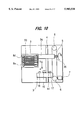
- FIG. 17 shows a construction of autochanger which is Embodiment-8.
- FIG. 18(A) shows a planar view of the tray holding a recording/reproducing possible disk in the autochanger shown in FIG. 17.
- FIG. 18(B) shows a planar view of the tray holding a reproducing-only disk used in the autochanger shown in FIG. 17.
- FIGS. 19(A) and 19(B) show an operation of the autochanger shown in FIG. 17 in detecting the disk-insertion and the disk type.
- FIG. 20 shows an example of output signal pattern of the sensor in detecting the disk insertion and the disk type in a case shown in FIGS. 19(A) and 19(B).
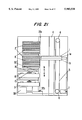
- FIG. 21 shows a construction of autochanger which is Embodiment-9.
- FIG. 22 shows a construction of autochanger which is Embodiment-10.
- FIG. 23 shows a planar view of the tray used in the automatic disk changer shown in FIG. 22.
- FIG. 1 shows an autochanger which is the first embodiment of the invention.
- tray carrier 1 is guided on guide shaft 4, and is driven by belt 5 through pulley 6 driven by driving motor 7.
- the tray carrier 1 takes out a tray 8a holding a disk (not shown) from the tray storage, or tray holder, or magazine 2, transports tray 8a in a direction of arrow-(a) and places the tray on the drive 3 for driving a recording-only disk and a recording/reproducing possible disk.
- a depression 9 is provided on tray 8a for the placement of a disk.
- the opening 10 allows the insertion of pickup 16 of drive 3 and turntable 15, and a positioning hole 13 is for determining the position of the tray to drive 3.
- a sensor hole 11 for identifying a reproducing-only disk is provided on the tray 8a at a position corresponding to a switch 17 acting as a detector on the drive 3.
- a notch 12 for enabling the disk pulling-out/insertion operations easily is provided on the tray 8a.
- a turntable 15 for rotating the disk placed on drive 3 pickup 16 guided by guide 19 for reading the signal from a disk.
- the pickup 16 is moved in the radial direction relative to a disk by means of a linear motor for example.
- a positioning pin 14 that corresponds to the positioning hole 13 on tray 8a
- switch 17 for determining the type of disk is on the tray, e.g., whether it is a reproducing-only or a recording/reproducing possible disk
- a switch 18 that acts as a detector for determining the possibility of recording/erasing in handling a recording/reproducing possible disk, are also provided on the drive 3.
- Tray carrier 1 is moved by belt 5 that is driven by motor 7 in either the direction shown by arrow (a) or (b) to a position corresponding to a specific tray 8a. Then, a specific tray 8a, on which a disk (not shown) has been placed in the depression 9 provided on tray 8a, is fetched from the tray storage 2 by utilizing the notch 12 on the tray 8a.
- tray carrier 1 with the fetched holding tray 8a is moved in a direction of arrow (a) and the positioning hole 13 of tray 8a is engaged with positioning pin 14 of drive 3, setting tray 8a on drive 3.
- turntable 15 and pickup 16 of drive 3 are inserted into opening 10, and at the same time, the disk placed on tray 8a is clamped on turntable 15 by using a clamp (not shown) provided on tray carrier 1. Synchronized with this motion, when sensor hole 11 provided on tray 8a is detected by switch 17, the disk placed on drive 3 is confirmed as a reproducing-only disk, such as CD-ROM.
- the controllers and the demodulation circuit including the disk rotation control circuit (e.g., CLV controller) for reproduction controlling the gain of controller and the phase compensation circuit are switched according to the inserted disk.
- the disk rotation control circuit e.g., CLV controller
- pickup 16 starts the operation of signal reproducing.
- the position of tray 8a on drive 3 is determined at this condition, and is held within tray carrier 1 at a height avoiding the chances of contact with the disk.
- tray carrier 1 As soon as the turntable 15 stops, tray carrier 1 is moved in the direction of arrow (b) by a driving motor 7. After the clamp (not shown), which is clamping the disk onto turntable 15, is disengaged, tray carrier 1 carries tray 8a, which is holding a disk in depression 9, to a predetermined position within tray storage 2. After this, the tray 8a is returned into tray storage 2 by using the notch 12.
- FIG. 4 shows a tray 8b designed for a recording/reproducing possible disk
- FIG. 5 shows an enlarged partial view of the same tray. A detailed structure of the tray for a recording/reproducing possible disk is now described below referring to FIGS. 4 and 5.
- the tray 8b has some of the same components as those disclosed above for the tray 8a for the reproducing-only disk, the same components in FIGS. 4 and 5 are identified by same numbers, and the individual explanations for these are omitted here.
- a sensor hole 26 is disposed on tray 8b at a position facing switch 18 for detecting the recording/erasing operation on drive 3.
- a slider 20 is disposed to cover sensor hole 26. This slider 20 is freely movable or guided in a guide groove 25. In a normal condition, the sensor hole 26 is kept covered.
- a locking nail 21, provided together with slider 20, is engaged with depression 22 provided on tray 8b when the sensor hole 26 is covered. In this position, a recording/reproducing possible disk on tray 8b is in a recording/erasing possible condition.
- the relationship between the sensor hole 26 and the detection switch 18 can be reversed.
- the relationship is so constructed that the recording/erasing is possible only when sensor hole 26 is exposed.
- tray 8b designed for a recording/reproducing possible disk Since the operations of autochanger using tray 8b designed for a recording/reproducing possible disk are fundamentally identical with that the case employing the before-mentioned tray 8a designed for a reproducing only disk, only the differences between the two trays are now explained below.
- tray 8b At a condition where the sensor hole 26 of tray 8b is covered by slider 20, when tray 8b is placed on drive 3, tray 8b is judged to be in a recording/erasing possible condition by switch 18, and thus, a normal recording/reproducing or erasing operation is conducted.
- tray 8b is judged to be in a recording/erasing impossible condition.
- tray 8b is returned into the original position in tray storage 2 after an error message is sent to the host computer from the autochanger.
- the space-efficiency of autochanger can be improved substantially, and moreover, by providing a disk-type discriminating means on the tray, a mixed operation of reproducing-only disks and recording/reproducing possible disks within the autochanger becomes possible. Therefore, the autochanger of the present invention can be offered, and the applications of such can be expanded considerably.
- the explanations so far have been directed at the structural difference between the tray designed for a reproducing-only disk and the tray designed for a recording/reproducing possible disk, which is very little.
- the number of tray types can be reduced into one type of tray by disposing two sensor holes side-by-side and by changing the structure of the sensor hole 11 provided on tray 8a designed for the reproducing-only disk.
- the structure of the sensor hole 11 may be changed into the one wherein the setting can be varied by employing a slider having a structure like the one for the sensor hole 26 provided on tray 8b designed for a recording/reproducing possible disk.
- the recording/reproducing possible condition may well be recognized by the closed conditions of sensor holes 11 and 26, recording/erasing impossible condition by the opened sensor hole 11 and the closed sensor hole 26, and the reproducing--only disk can be recognized by the opened condition of both sensors 11 and 26.
- These conditions can be realized by storing two empty trays in the tray storage 2 initially and by changing the setting into the one like above-shown later according to the necessity.
- notch 12 of tray is provided to hold down the tray during the transportation, the shape is not necessarily be limited to the one shown here, but symmetrically with notch 12, the same notch may be provided on the other end of tray. More-over, in a case where either the recording/reproducing possible disks or the reproducing-only disks are inserted in a casing such as a cartridge of determined shape, said cartridge can be used in the invented autochanger without applying any alternations thereto by copying the shapes and positions of the notch and detection holes on a current cartridge.
- FIG. 6 shows a so-called magazine in which the tray storage holding trays 8b explained in Embodiment-1 are made detachable
- FIGS. 7(A) and 7(B) shows an partial enlargement thereof.
- FIG. 6 shows a case where magazine 27 holds six trays 8b, wherein sliders 20 are disposed in a row on the front of each tray.
- a lock mechanism (not shown) operates to prevent a user from easily pulling-out a tray 8b.
- Cutout 28 is provided on magazine 27 in order to make the pulling out of a tray from the magazine by a tray carrier of an autochanger easy. In this manner, the notch 12 is exposed from the shell of magazine 27.
- FIG. 7(A) shows a partial enlargement of slider 20, which is in a condition where trays 8b are completely held within magazine 27.
- the operations of slider 20 is now explained by referring to FIGS. 7(A) and 7(B).
- slider 20 of the second tray from the top is moved in a direction shown by arrow (N) to a position explained in the previous section by inserting a mechanical pencil 29 having a very sharp point into the operation hole 24. The completion of this movement is shown in FIG. 7(B).
- the condition of recording/erasing of the disk can be individually set and easily determined at a result of viewing the set condition of the trays held in the magazine.
- FIGS. 8(A) and 8(B) show a structure of another magazine, which is different from the magazine of Embodiment-2, and this is now explained by referring FIGS. 8(A) and 8(B).
- FIG. 8(A) A partially pulled-out tray 8c for a recording/reproducing possible disk is shown in FIG. 8(A).
- the tray 8c is held in a magazine 30 with the opening 10 in the tray being on the open side of magazine 30.
- a sensor hole 26 and slider 20 (not visible) are disposed on the back of the diagonal line P.
- the trays are arranged in a direction opposite to the trays 8b in FIG. 6.
- the tray 8c is arranged in this manner to make the changer operable even if the drive mounted in the autochanger is inserted in a reverse direction.
- Tray 8c is characterized by the easiness to confirm the possibility of recording/erasing of disk.
- an operating window 31, shown in FIG. 8(B) is provided on the rear of magazine 30.
- all of the sliders 20 placed on trays 8c can be operated through the window 31.
- the user is able to set the possibility of recording/erasing of disk from the side of magazine without detaching the magazine inserted in the autochanger, and these setting operations are identical with the ones explained in connection with the second embodiment depicted in FIGS. 6, 7(A) and 7(B).
- FIG. 9 shows an embodiment of autochanger employing a magazine explained before in connection with FIG. 6.
- a cutout 28 (FIG. 6), which makes the aforementioned tray pulling out/insertion operations by tray carrier 1 easier, is provided in each tray held in the magazine 27.
- a loading mechanism 32 for holding the tray, loading and clamping the disk on turntable 15 is provided on the drive 3.
- two drives 3 are employed in the autochanger.
- a tray carrier 1 takes a tray out of the magazine holding the tray and moves the tray in a direction shown by arrow (a). Then the tray carrier 1 inserts the tray into a specified loading mechanism 32 of drive 3. The loading mechanism 32 clamps the disk on a turntable 15, and at the same time, the recording/erasing possibility of the disk is confirmed by switch 18. When this is affirmed, a recording/reproducing or erasing operation is carried out. However, when this is denied, a denial operation is performed. For example, the tray is returned to the original magazine 27, and at the same time, an error message is sent to the host computer.
- the autochanger of Embodiment-4 has an advantage of the efficient use of space by the tray system. Also, the mixed use of reproducing-only disks and the recording/reproducing possible disks is possible in this case.
- the confirmation of such can be performed before the disks are installed on two drives, one of which is used as a reproduction-only drive, and the other of which is used as a recording/reproducing possible drive. This is highly effective to prevent the erratic disk insertion.
- FIG. 10 shows an autochanger of Embodiment-5.
- a tray 8d holding disk 33 is taken out of the tray storage 2 by the tray carrier 34, and is moved in a direction of arrow (a), and is placed on drive 3.
- Tray carrier 34 is made to hold two trays 8d simultaneously, and is so constructed that each of these trays 8d can make a 180 degree rotation by means of reversing motor 35. Then, tray 8d is guided along guide shaft 4, and is driven by driving motor 7, through the pulleys 6 and belt 5.
- Plural trays 8d holding disks individually thereon are held in tray storage 2 in advance, and at the same time, an empty tray 8e is held in an upside-down condition of tray 8d in a space below the tray storage 2.
- Depression 9 for holding a disk and, at the same time, opening 10 allowing for the insertions of pickup 16 of drive 3 and turntable 15, are provided on tray 8d, as shown in FIG. 12.
- a turntable 15 for rotating the disk placed on drive 3, and a pickup 16 guided by guide 19 for reading the signal from a disk, are shown mounted on the autochanger in FIG. 11.
- a positioning hole 13 for determining the relative position of the tray to drive 3; a sensor hole 11 for identifying the reproducing-only disk on the tray, wherein the sensor hole 11 is placed in a position on the tray that corresponds to a switch 17 mounted on drive 3; and notches 12 allowing for the taking-out/insertion of the tray from/to the tray storage 2.
- the turntable 15 is guided by a linear motor or such, and the pickup 16, which is guided by the pickup guide 19 in a radial direction of disk, is for reading out signals from the disk.
- a switch 17 and a positioning pin 14 are further provided on the drive 3 with the positioning pin 14 at a position corresponding to the positioning hole 13 of tray 8d. The type of the disk placed on drive 3 is determined by switch 17, which determines whether the disc is a reproducing-only disk or a recording/reproducing possible disk.
- the tray carrier 34 is driven by belt 5, which is further driven by a driving motor 7 in either direction of arrow (a) or (b), and is moved to a position of a specified tray 8d. After this, a tray 8d holding disk 33 in the depression 9 thereof is taken out or removed from tray storage 2 by utilizing the notches 12.
- tray carrier 34 holding a tray 8d is moved to a direction of arrow (a), positioning hole 13 of tray 8d is engaged with positioning pin 14 of drive 3, and the position of tray 8d relative to drive 3 is determined.
- the turntable 15 of drive 3 and the pickup 16 are inserted into the opening 10, and at the same time, centering of disk 33 placed on tray 8d on turntable 15 is made, and the disk is clamped on turntable 15 by a clamp (not shown) disposed on tray carrier 34.
- the type of disk placed on drive 3 is determined, e.g., whether the disk is a reproducing-only type like a CD-ROM, or a recording/reproducing possible type. Then, after performing the switching of a rotation control circuit (such as CLV) matched to the disk, the readout of signals are performed by using pickup 16. Moreover, tray 8d in this condition is positioned on drive 3, and is held within tray carrier 34 at a elevated height avoiding the contact with the disk.
- a rotation control circuit such as CLV
- tray carrier 34 is moved to a direction of arrow (b) by the driving motor 7, and the clamp holding the disk onto turntable 15 is released. Then, tray 8d holding disk 33 in depression 9 is transferred to a predetermined position in the tray storage 2, and is returned into tray storage 2 by means of the notches 12.
- a tray carrier 34 having taken out or removed a tray 8d holding a disk 33 is moved in a direction of arrow (a) by belt 5, and is stopped at a position corresponding to the empty tray 8e. This position is determined by a photocoupler and a mirror not shown here. At this condition, tray carrier 34 moves the empty tray 8e into a position right above the previously removed tray 8d holding disk 33. The tray carrier 34 is then rotated 180 degrees by the operation of a reversing motor 35, and the disk 33 is then transferred from the tray 8d and placed on the empty tray 8e. This means that the disk 33 is reversed and placed on empty tray 8e, and the recording/reproducing of the reversed surface of disk 33 becomes possible after completing the migration or movement of the tray carrier 34 to drive 3.
- the storage or return of disk 33 to the tray holder 2 is conducted as follows. Before the disc 33 is returned, a 180 degree reversing operation of tray carrier 34 is performed with the disc being returned to the tray 8d from the tray 8e. Then, the disk 33 is stored into a predetermined position in tray storage 2. By these operations, the disk 33 is stored in the same condition as the initial condition. The series of operations involved in returning the disc to its original position is then completed by returning the empty tray 8e to its original position in the tray storage 2.
- the number of the drives can be increased in accordance what is necessary.
- the extra advantage of enabling the recording/reproducing of reversed surfaces on each drive is realized by providing a plurality of empty trays in accordance with the number of drives.
- Embodiment-6 of the invention is shown in FIG. 14 and FIGS. 15(A)-15(C). Since the components shown in these figures are the same as those in Embodiment-5, the same components are identified with the same numbers as Embodiment-5, and the explanation of such components is omitted here.
- Embodiment-6 shows a construction where the empty tray 8e is held in the tray carrier 36, rather than in the disc holder 2.
- this construction there is no need for the tray carrier to retrieve an empty tray, and then to return the empty tray following its usage of positioning the reverse side of a disk on a drive.
- Embodiment-6 provides the advantage of requiring less time to produce a disk change. In particular, this means that the operation of pulling out and returning an empty tray 8e to and from the tray storage 2 is excluded from the total operations, while the other operations remain same as the ones shown in Embodiment-5.
- FIG. 16 shows a typical autochanger equipped with a tray storage in which magazines 27 are detachably mounted.
- each magazine 27 holds a plurality of trays in which disks are individually held.
- the tray carrier 36 holds an empty tray in advance, as explained in Embodiment-6.
- a drive 3 holds a tray and a loading mechanism 32 for placing a disk on the turntable 15 and for clamping a disc thereto. Two drives 3 are provided in this autochanger, and the operation thereof is explained in next.
- the tray carrier 36 in the case where the desired tray is taken out and inserted on the drive, is left as it is.
- the disk is transferred into the empty tray by the operation of reversing motor 35.
- the tray carrier After the tray carrier is moved in the a direction of arrow (a), the tray is inserted into loading mechanism 32 of drive 3, and then, the disk is clamped on turntable 15 by means of the loading mechanism 32 before the operation of recording/reproducing is started.
- the disk In returning the disk, the disk is taken from the drive 3 by the tray carrier 36, and is moved in the direction of arrow (b), and is placed back into a predetermined position of magazine 27.
- the disk is transferred to the original tray by the operation of the reversing motor 35, and the tray is returned to its predetermined location in the magazine.
- the autochanger of this system is able to insert a desired disk selectively into one of the drives according to the number of drives.
- a construction storing an empty tray in the tray storage, as explained in Embodiment-5 and shown in FIG. 10 (a construction providing a space storing plural number of drives under magazine 27), can be employed in this case. Recording/reproducing of the reversed or rear surface of a disk placed on each drive can be performed by performing the operation explained in connection with Embodiment-5.
- Embodiments 5, 6, and 7 have been made on a precondition that the dimensions of the empty tray and the tray with a disk are the same, in an application where the device is has a large number of drives and a small number of tray carriers, the surface directions of the disks held in the tray storage 2 can be maintained in a predetermined direction by making the of shape of notch 12 different, for example, or by providing another sensor hole and other means.
- FIGS. 17 and 18 The structure and operation of Embodiment-8 are now explained below by referring FIGS. 17 and 18.
- a tray carrier 1 pulls out a tray 8f or 8g holding a disk (not shown) stored in a magazine 2. Then the tray carrier 1, moves along a direction shown by arrow (a) to the position of a loading mechanism 32 and drive 3.
- the tray carrier 1 is guided by guide shaft 4 and is driven by a belt 5 and a driving motor 7 through the pulleys 6.
- a depression 9 for holding a disk is provided on tray 8f and tray 8g.
- an opening 10, which allows the insertions of a pickup 16 of drive 3 and a turntable 15; positioning hole 13 for determining the position of the tray to drive 3; and notch 12, which allows the tray to be pulled-out/inserted from/into the magazine 2 to tray carrier 1; are provided.
- a turntable 15 for rotating the disk placed thereon, a pickup 16 for reading the signals recorded on the disk, and a positioning pin 14 for determining the relative positions of tray 8f and tray 8g, are provided on drive 3 mounted in the auto-changer.
- Sensors 37a and 37b are provided at the positions that correspond to the positions of a disk-type discriminating hole 39 (FIG. 18(A)) and disk presence detecting hole 40 (FIG. 18(B)) provided on the trays 8f and 8g.
- the tray 8f shown in FIG. 18(A), is a tray designed for a recording/reproducing possible disk
- the tray 8g shown in FIG. 18(B) is a tray designed for a reproducing-only disk.
- the disk-type discriminating hole 39 is blocked.
- a controller 38 controlling the operation of autochanger and managing the information of the disks according to the commands from a host computer (not shown) and the operation buttons is provided.
- Embodiment-8 When an instruction commanding the placing of a specified disk on the drive 3 is externally inputted to controller 38, the tray carrier 1 is driven by driving motor 7 through belt 5, and is moved along a direction shown by arrows (a) or (b), based on the output signal of controller 38. The tray carrier is brought to a position corresponding to the specified trays 8f and 8g. Next, the tray carrier 1 pulls out trays 8f and 8g, by using notch 12 on the trays, from the magazine 27.
- the tray carrier 1, holding trays 8f and 8g, is then moved along a direction of arrow (a), and the trays inserted into loading mechanism 32.
- the loading mechanism 32 makes the positioning holes of trays 8f and 8g engage with the positioning pin 14 of drive 3, thereby accomplishing the positioning of trays 8f and 8g on the drive 3.
- controller 38 sends out an instruction signal to drive 3 to insert turntable 15 and pickup 16 of drive 3 into the opening 10, and at the same time, and to perform the centering of the disk placed on trays 8f and 8g on turntable 15. Then, the disk is clamped on turntable 15 by means of a clamp (not shown) provided on the loading mechanism 32. After this, the turntable 15 is rotated and the signal is readout by using pickup 16. Moreover, trays 8f and 8g are, at this condition, clamped and held at a height avoiding a contact with the disk by means of the loading mechanism 32.
- FIGS. 19(A), 19(B) and 20 The explanation of the structure shown in FIGS. 19(A) and 19(B) is described by referring to tray 8f, which is designed for the recording/reproducing possible disks.
- initialization A series of operations conducted at the starting of a power supply and the tray exchange including the storage of various information such as the presence and the type of disk and others in controller 38 are called initialization.
- the presence and types of disks can be identified by using controller 38 by which all of the trays are sequentially transferred to the drive by using tray carrier 1 for the initialization.
- controller 38 the total time required for the transfer of all the disks and the total time to place all the disks sequentially on the drive would be very long. Since this would be very phenomenal when a large number of disks are stored and the execution of the other operations would become impossible, so that the operation efficiency of total system would drop sharply.
- controller 38 sends an instruction to tray carrier 1 commanding a sequential pull-out of all the trays 8f from magazine 2 in a direction shown by arrow (d) shown in FIGS. 19 (A) and 19 (B).
- each of sensors 37a and 37b consisting of a light emitter and a light sensor respectively, are disposed in mutually opposing positions respectively, corresponding to the disk-type confirming hole 39 and the disk presence confirming hole 40 disposed respectively on the tray 8f, so that the situations of these sensor-holes provided on tray 8f can be confirmed.
- an intermediate switch 41 which operates when the disk presence confirming hole 40 provided on tray 8f passes through sensor 37b, is disposed on the tray carrier 1.
- a mechanical switch acting as an intermediate switch is shown, a magnetic or optical switch can be used just as well.
- FIG. 19(A) shows a condition where tray 8f is held within the magazine
- FIG. 19(B) shows a condition where tray 8f is pulled out of the magazine causing an operation of intermediate switch 41.
- FIG. 20 shows the changes in the outputs of intermediate switch 41 and sensor 37b as the tray 8f is being pulled out.
- (0) shows the output signal of intermediate switch 41
- (1)-(5) show the changes of the output signal of sensor 37b.
- Each of these shows a combination of sensor outputs showing various conditions produced by the combinations of the type of disk, presence of disk, presence of tray, etc.
- the operation of the intermediate switch is shown by H, while the none-operations of the same are shown by L.
- the light detection of sensor 37b is shown by H, while the none-detection is shown by L, and the other conditions are expressed likewise also.
- Point-(A) in FIG. 20 corresponds to the condition shown in FIG. 19(A), point-(C) corresponds to the condition shown in FIG. 19(B), and point-(B) corresponds to the period during which disk presence confirming hole 40 passes over sensor 37b.
- the disk type confirming hole 39 can be allocated generally to identify any of conditions including, the open-closed condition, a recording/reproducing possible disk, and a reproducing-only disk, in this embodiment, the opened condition of the hole means a recording/reproducing possible disk, and the closed condition means a reproducing-only disk.
- Table 1 shows a list of the standards identifying the presence of tray, type of disk, and disk presence when any of the outputs of (1)-(5) is obtained.
- the controller 38 monitors the outputs of sensor 37b and intermediate switch 41, and memorizes the number of times that the output of sensor 37b changed in a way H ⁇ L. At the same time, by detecting the output level of sensor 37b, when the output of intermediate switch 41 becomes H, the presence of tray, type of disk, e.g., whether it is a recording/reproducing possible disk or a reproducing-only disk, and the presence of disk can be confirmed from Table 1.
- the presence of a tray is confirmed, except in the case where the number of times that the output of sensor 37b is changed in a way H ⁇ L is zero, until the intermediate switch 41 is operated. Moreover, the presence of recording/reproducing possible disk is confirmed when the number of times of said phenomena is more than two. The presence of a reproducing only disk is confirmed when the number of times is only one.
- the disk presence information As for the disk presence information, a condition, where the intermediate switch 41 is in a state of H and the output of sensor 37b is L, is recognized as a presence of disk, while no presence of a disk is recognized when the output is H.
- the condition where the tray or the disk is spilled out of the magazine 2 can be differentiated from either of the cases shown in Table 1, since the signal of sensor 37b is L.
- this case can be recognized as an error where the disk/tray is spilled.
- the drive capable of processing both the recording/reproducing possible disks and the reproducing-only disks can be employed in this embodiment. Even in a case employing a drive dedicated to the recording/reproducing possible disks or a drive dedicated to the reproducing-only disks, the management of disk information can be performed by employing the dedicated trays for each and by performing the same processings. Thus, the device expansion can be easily made if so desired, since the type of disk can be discriminated by employing proper trays.
- the disk-type information is manageable by the type of tray in this embodiment, in a case where the drive capable of processing both a recording/reproducing possible disk and a reproducing-only disk is employed, an extra disk type discriminating means may be provided on the drive also. By this, a higher device reliability can be obtained, since the final discrimination can be performed at the drive, even if an erratic disk type information is produced at the controller for some reason or another.
- the disk-type discrimination means in the drive may be realized by utilizing disk-type discriminating hole 39 disposed on the tray or by using another discriminating hole disposed on the tray.
- FIG. 21 shows Embodiment-9 provided with two magazines 2 and two drives 3, and a tray carrier 1 capable of holding plural disks simultaneously.
- Embodiment-9 is different from Embodiment-8 in these aspects.
- the tray carrier 1 consists of tray carriers 1a and 1b, and is able to hold two disks simultaneously.
- Embodiment-9 for exchanging a disk held in drive 3 with a disk held in magazine 2 are explained next. This is a common and most frequently performed operation of a disk changer.
- the tray carrier 1 When an instruction calling for the exchange one disk with another disk is issued from the controller 38, the tray carrier 1 is moved to the position of the tray in the tray holder 2 where the disk to be processed next is located, and this specified tray is taken out by the tray carrier 1a.
- the tray carrier 1b is left in an empty condition at this time.
- the tray carrier 1 is moved in the direction of the arrow (a). Then, the position of tray carrier 1b relative to the loading mechanism 32 is determined. At this time, the tray holding the disk being processed by drive 3 is taken out by loading mechanism 32 and transferred to the tray carrier 1b.
- tray carrier 1a relative to the loading mechanism 32 is determined. After determining the position of tray carrier la relative to loading mechanism 32, the tray holding the disk to be processed in next is inserted into loading mechanism 32. Then, the disk is clamped on turntable 15 by loading mechanism 32 and rotated with the signal being readout by the pickup 16.
- Tray carrier 1b is moved to a position relative to the predetermined position of the tray holder 2, and the tray is returned to the holder by using the notch 12.
- Embodiment-9 The detailed explanation of the disk information management conducted in an autochanger of Embodiment-9 is omitted here since these are performed in a way similar to that of Embodiment-8.
- tray carriers, 1a or 1b In a case where all of the trays have to be pulled out of magazine 2 for management of disk information, either of tray carriers, 1a or 1b, has to be used avoiding the simultaneous use of these two, and tray 1a is consistently used in this case.
- Embodiment-9 needless to say that the initialization process is performed by detecting the presence of tray, type of disks, and the disk presence by a sensor pair (sensors 37a and 37b), and by memorizing these results in the controller. Since the abnormal positioning of tray/disk is detectable also, an autochanger of simple construction, performing the initialization processes in a short time can be offered.
- Embodiment-10 is next explained by referring FIGS. 22 and 23.
- a tray 8 holding a disk (not shown), held in a magazine 2 (a or b) is taken out by the tray carrier 1, and is transferred in a direction shown by arrow (a) and placed on drive 3.
- Tray carrier 1 is guided by a guide shaft 4 and is driven by a belt 5 driven by motor 7 through pulleys 6.
- Plural trays 8 are held in magazine 2, which is freely interchangeable by a user by operating the door 45.
- loading sensors 42a and 42b for detecting the loading or unloading of each magazine 2a and 2b are provided also.
- tray 8 there are provided on tray 8: a depression 9 for holding a disk; an opening 10 allowing the passages of pickup 16 and turntable 15; a positioning hole 13 for determining the relative position of the tray to drive 3; and a notch 12 for making the taking in and out of the tray from/to a magazine 2 easy.
- a turntable 15 for rotating the disk a pickup 16 for reading out the signal recorded on the disk, and a positioning pin 14 corresponding to positioning hole 13 of tray 8, are provided also on the drive 3 mounted on the autochanger.
- a transfer controller 43 controls the driving motor 7 and the tray carrier 1, and a drive controller 44 controls the drive 3.
- a controller 38 gives driving instructions to the transfer controller 43 and the drive controller 44, and the controller 38 controls and manages the operation of the autochanger and disk information based on the input to the host computer (not shown) and operating buttons (not shown).
- controller 38 Based on the output of controller 38, the transfer controller 43 generates an instruction to start the operations of the driving motor 7 and the tray carrier 1.
- the tray carrier 1 is thus driven in a direction shown by either arrow (a) or (b) by the driving motor 7 through belt 5, and is moved to a specified position to remove a tray 8.
- the tray carrier 1, holding tray 8, is transferred in the direction of arrow (a), and positioning hole 13 of tray 9 is engaged with the positioning pin 14 of the drive 3, thereby determining the position of tray 8 with respect to the drive 3.
- the controller 38 outputs an instruction to drive the controller 44 in order to introduce turntable 15 and pickup 16 on drive 3 through the opening 10, to perform a centering operation of the disk on turntable 15, and to clamp the disk on turntable 15 by means of a clamp (not shown) provided on tray carrier 1.
- tray 8 is positioned on drive 3 and is held within tray carrier 1 at a height avoiding the possible contact with the disk. The return of tray 8 after ending the reproducing operation is conducted in a manner described next.
- the tray carrier 1 When the rotation of turntable 15 is stopped by the drive controller 44 according to the instruction signal given by controller 38, the tray carrier 1 is moved by means of the driving motor 7 in a direction shown by arrow (b) by an instruction from the movement or transfer controller 43, after the clamp holding the disk to turntable 15 is released.
- the disk placed on tray 8 is transferred to a predetermined position of the magazine 2, and is returned into the magazine 2 by utilizing the notch 12.
- the initialization processes of this autochanger at the time of power turn-on begin with a sending of an instruction command from the controller 38 to the transfer controller 43.
- the disk presence, type of disks, and tray presence are identified by a disk information sensor (not shown) after taking out all of the trays by utilizing the tray carrier.
- the disk-type may well be identified by transferring the tray to drive 3 and by placing the disk on drive 3.
- the data information recorded on the disk may be identified and the writing of management information may be conducted in a case of recording/reproducing media.
- the storage of such disk-related information on the controller 38 is conducted in a way similar to the ones described in connection with Embodiments-8 and -9.
- the signal from the instal sensor 42a is detected by controller 38. If the signal from instal sensor 42b is monitored and the presence of unexchanged magazine 2b is detected, an instruction commanding the before-mentioned initialization of the trays and disks held in the exchanged magazine 2a is outputted to carrier controller 43 and drive controller 44, and only the information relating to the disks held in magazine 2a are updated and the old information held in the unchanged magazine are maintained as they are.
- the time required for initialization can be reduced substantially by performing the initialization and by updating the data only with respect to the exchanged magazine. Moreover, a higher operating efficiency of the autochanger and a higher total efficiency of the system including the autochanger can be realized.
- this embodiment is of a construction capable of changing the disks in a magazine unit, the time for initialization can be reduced likewise if a sensor detecting the exchange of tray or cartridge is provided, even in a case of autochanger holding and managing the disks in an unit of disk-holding tray or cartridge.
- a disk-type discrimination means may also be provided in the drive when a drive operable for both the recording/reproducing possible disk and the reproducing-only disk is employed.
- Embodiments-1 to -10 though it is most desirable to employ a drive operable for both the recording/reproducing possible disk and the reproducing only disk, the effects would be the same if drives operable only for the recording/reproducing possible disk and drives operable only for the reproducing only disk, in a case where plural drives have to be incorporated.
Landscapes
- Automatic Disk Changers (AREA)
Applications Claiming Priority (8)
| Application Number | Priority Date | Filing Date | Title |
|---|---|---|---|
| JP31039494A JP2940421B2 (ja) | 1994-12-14 | 1994-12-14 | 媒体用トレー、それを用いるマガジン及び媒体自動交換装置 |
| JP6-310394 | 1994-12-14 | ||
| JP7-051257 | 1995-03-10 | ||
| JP05125795A JP3480100B2 (ja) | 1995-03-10 | 1995-03-10 | 媒体自動交換装置 |
| JP7-160420 | 1995-06-27 | ||
| JP7160420A JPH0917164A (ja) | 1995-06-27 | 1995-06-27 | 媒体自動交換装置 |
| JP16345295A JP3248396B2 (ja) | 1995-06-29 | 1995-06-29 | 媒体自動交換装置および媒体用トレー |
| JP7-163452 | 1995-06-29 |
Publications (1)
| Publication Number | Publication Date |
|---|---|
| US5903538A true US5903538A (en) | 1999-05-11 |
Family
ID=27462608
Family Applications (1)
| Application Number | Title | Priority Date | Filing Date |
|---|---|---|---|
| US08/571,453 Expired - Fee Related US5903538A (en) | 1994-12-14 | 1995-12-13 | Automatic disk change apparatus and disk tray for the apparatus |
Country Status (4)
| Country | Link |
|---|---|
| US (1) | US5903538A (fr) |
| EP (1) | EP0717405B1 (fr) |
| CN (1) | CN1206647C (fr) |
| DE (1) | DE69523873T2 (fr) |
Cited By (48)
| Publication number | Priority date | Publication date | Assignee | Title |
|---|---|---|---|---|
| US6111848A (en) * | 1999-01-07 | 2000-08-29 | Hui; John | Compact disc storage and retrieval system |
| US6118751A (en) * | 1994-07-14 | 2000-09-12 | Matsushita Electric Industrial Co., Ltd. | Disk cartridge, disk drive and disk changer apparatus using the disk cartridge, and method for handling the disk cartridge |
| US6130744A (en) * | 1997-04-17 | 2000-10-10 | Alps Electric Co., Ltd. | Optical disk discriminating method, including memory storage, for automatic multiple-disk changer |
| US6169711B1 (en) * | 1997-07-29 | 2001-01-02 | Samsung Electronics Co., Ltd. | Technique for controlling motion of disk tray and pickup |
| US6333911B1 (en) * | 1997-03-31 | 2001-12-25 | Clarion Co. Ltd. | Disk playback apparatus disk changer device and disk magazine device |
| WO2002019107A1 (fr) * | 1999-01-07 | 2002-03-07 | John Hui | Systeme de rangement et de recuperation de disques compacts |
| US6442127B2 (en) * | 1998-03-11 | 2002-08-27 | Hitachi Electronic Engineering Co., Ltd. | Mount for recording media and recording media library apparatus using the mount |
| US6532197B1 (en) * | 1999-11-01 | 2003-03-11 | Wing Sang Cheung | Automatic data disc storage and selection system |
| US6628600B1 (en) * | 1999-08-06 | 2003-09-30 | Pioneer Corporation | Disc changer |
| US20040020980A1 (en) * | 2002-07-31 | 2004-02-05 | Whiteing Vernon N. | System for scanning, processing, and storing disk |
| US20040027933A1 (en) * | 1999-03-04 | 2004-02-12 | Pioneer Electronic Corporation | Disc changer |
| US20040181747A1 (en) * | 2001-11-19 | 2004-09-16 | Hull Jonathan J. | Multimedia print driver dialog interfaces |
| US20040194026A1 (en) * | 2003-03-31 | 2004-09-30 | Ricoh Company, Ltd. | Method and apparatus for composing multimedia documents |
| US20040213141A1 (en) * | 2003-04-25 | 2004-10-28 | Lin Ju Shan | Storage device assembly incorporating ejecting mechanism with safety latch |
| US20050005760A1 (en) * | 2001-11-19 | 2005-01-13 | Hull Jonathan J. | Music processing printer |
| US20050008221A1 (en) * | 2001-11-19 | 2005-01-13 | Hull Jonathan J. | Printing system with embedded audio/video content recognition and processing |
| US20050022122A1 (en) * | 2003-03-31 | 2005-01-27 | John Barrus | Document collection manipulation |
| US20050024682A1 (en) * | 2000-11-30 | 2005-02-03 | Hull Jonathan J. | Printer with embedded retrieval and publishing interface |
| US20050034057A1 (en) * | 2001-11-19 | 2005-02-10 | Hull Jonathan J. | Printer with audio/video localization |
| US20050050344A1 (en) * | 2003-08-11 | 2005-03-03 | Hull Jonathan J. | Multimedia output device having embedded encryption functionality |
| US20050069362A1 (en) * | 2003-09-25 | 2005-03-31 | Hart Peter E. | Printer having embedded functionality for printing time-based media |
| US20050068569A1 (en) * | 2003-09-25 | 2005-03-31 | Hull Jonathan J. | Printer with document-triggered processing |
| US20050068567A1 (en) * | 2003-09-25 | 2005-03-31 | Hull Jonathan J. | Printer with audio or video receiver, recorder, and real-time content-based processing logic |
| US20050071746A1 (en) * | 2003-09-25 | 2005-03-31 | Hart Peter E. | Networked printer with hardware and software interfaces for peripheral devices |
| US20050071519A1 (en) * | 2003-09-25 | 2005-03-31 | Hart Peter E. | Stand alone printer with hardware / software interfaces for sharing multimedia processing |
| US20050068568A1 (en) * | 2003-09-25 | 2005-03-31 | Hart Peter E. | User interface for networked printer |
| US20050071520A1 (en) * | 2003-09-25 | 2005-03-31 | Hull Jonathan J. | Printer with hardware and software interfaces for peripheral devices |
| US20050068571A1 (en) * | 2003-09-25 | 2005-03-31 | Hart Peter E. | Stand alone multimedia printer with user interface for allocating processing |
| US20050223309A1 (en) * | 2004-03-30 | 2005-10-06 | Dar-Shyang Lee | Multimedia projector-printer |
| US20060004751A1 (en) * | 2004-06-02 | 2006-01-05 | Funai Electric Co. Ltd. | Changer-type information recording apparatus |
| US20060010462A1 (en) * | 2004-07-07 | 2006-01-12 | Jui-Chiang Lin | Optical disc drive and optical disc cassette |
| US20060077631A1 (en) * | 2004-10-12 | 2006-04-13 | Pei-Shi Lin | Hinged panel and disc drive for a computer |
| US20060161944A1 (en) * | 2005-01-18 | 2006-07-20 | Imation Corp. | Multi-disk data cartridge |
| EP1518676A3 (fr) * | 2003-09-25 | 2006-10-11 | Ricoh Company, Ltd. | Imprimante multimédia adaptée au partage des tâches de traitement |
| US20060256388A1 (en) * | 2003-09-25 | 2006-11-16 | Berna Erol | Semantic classification and enhancement processing of images for printing applications |
| US20060262995A1 (en) * | 2003-03-31 | 2006-11-23 | John Barrus | Action stickers for identifying and processing stored documents |
| US20060294450A1 (en) * | 2003-03-31 | 2006-12-28 | John Barrus | Action stickers for nested collections |
| US20070058500A1 (en) * | 2001-04-17 | 2007-03-15 | Nobuaki Onagi | Disk drive system employing effective disk surface stabilization mechanism |
| US20080117726A1 (en) * | 2006-04-18 | 2008-05-22 | Hitachi Maxell, Ltd. | Optical disc recording and reproducing apparatus and disc autochanger |
| US7551312B1 (en) | 2005-03-17 | 2009-06-23 | Ricoh Co., Ltd. | Annotable document printer |
| US7570380B2 (en) | 2003-09-25 | 2009-08-04 | Ricoh Company, Ltd. | Printer user interface |
| US7573593B2 (en) | 2003-09-25 | 2009-08-11 | Ricoh Company, Ltd. | Printer with hardware and software interfaces for media devices |
| US7739583B2 (en) | 2003-03-31 | 2010-06-15 | Ricoh Company, Ltd. | Multimedia document sharing method and apparatus |
| US7747655B2 (en) | 2001-11-19 | 2010-06-29 | Ricoh Co. Ltd. | Printable representations for time-based media |
| US7864352B2 (en) | 2003-09-25 | 2011-01-04 | Ricoh Co. Ltd. | Printer with multimedia server |
| US8274666B2 (en) | 2004-03-30 | 2012-09-25 | Ricoh Co., Ltd. | Projector/printer for displaying or printing of documents |
| US20130263162A1 (en) * | 2012-03-28 | 2013-10-03 | Panasonic Corporation | Disc device |
| US10820443B2 (en) * | 2017-10-18 | 2020-10-27 | Sumitomo Electric Industries, Ltd. | Tray unit |
Families Citing this family (12)
| Publication number | Priority date | Publication date | Assignee | Title |
|---|---|---|---|---|
| US5581540A (en) * | 1995-02-08 | 1996-12-03 | International Business Machines Corporation | Single disk write protection system for multiple-disk cartridge |
| US5841743A (en) * | 1996-03-29 | 1998-11-24 | Matsushita Electric Industrial Co., Ltd. | Optical disk changer system and method of managing optical disk changer |
| JP3276566B2 (ja) * | 1996-09-25 | 2002-04-22 | アルプス電気株式会社 | ディスク装置 |
| JP3338303B2 (ja) * | 1996-09-25 | 2002-10-28 | アルプス電気株式会社 | ディスクパッケージ |
| JPH10106126A (ja) * | 1996-09-25 | 1998-04-24 | Alps Electric Co Ltd | ディスクパッケージ |
| JPH11110894A (ja) * | 1997-10-02 | 1999-04-23 | Alps Electric Co Ltd | 記録媒体の識別装置 |
| JP3269036B2 (ja) * | 1997-12-29 | 2002-03-25 | 株式会社アサカ | 反転機構を備えたディスク自動交換装置 |
| DE60112043T2 (de) | 2000-02-08 | 2006-04-20 | Thomson Licensing S.A. | Behälter für optische platten , plattenteller und plattenspieler vom magazintyp |
| EP1258875A1 (fr) * | 2001-05-18 | 2002-11-20 | Deutsche Thomson-Brandt Gmbh | Magasin à disque |
| JP2007079164A (ja) * | 2005-09-14 | 2007-03-29 | Fujifilm Corp | 光記録媒体及びその製造方法、並びに、光記録装置及び光再生装置 |
| CN111798877B (zh) * | 2019-04-09 | 2022-03-04 | 光宝电子(广州)有限公司 | 碟片库储存系统及用于此系统的片匣盒 |
| CN110931055B (zh) * | 2019-12-09 | 2022-01-04 | 唐山师范学院 | 一种音乐内容可调整式放音设备 |
Citations (15)
| Publication number | Priority date | Publication date | Assignee | Title |
|---|---|---|---|---|
| JPS6173265A (ja) * | 1984-09-18 | 1986-04-15 | Sharp Corp | デイスクプレ−ヤにおけるデイスク収納装置 |
| FR2575857A1 (fr) * | 1984-11-29 | 1986-07-11 | Canon Kk | Appareil de stockage optique d'informations |
| US4685095A (en) * | 1984-07-11 | 1987-08-04 | Filenet Corporation | Optical storage and retrieval device |
| EP0285866A2 (fr) * | 1987-04-07 | 1988-10-12 | Mitsubishi Denki Kabushiki Kaisha | Mémoire à disques |
| WO1988009033A1 (fr) * | 1987-05-07 | 1988-11-17 | Deutsche Thomson-Brandt Gmbh | Echangeur de disques compacts |
| US4800554A (en) * | 1986-10-01 | 1989-01-24 | Victor Company Of Japan, Limited | Disk magazine |
| US4827453A (en) * | 1986-12-26 | 1989-05-02 | Kabushiki Kaisha Toshiba | Semiconductor memory control circuit |
| JPH0469860A (ja) * | 1990-07-11 | 1992-03-05 | Nec Corp | 可換性ディスク種類判別方法 |
| DE4205912A1 (de) * | 1991-02-26 | 1992-08-27 | Victor Company Of Japan | Automatisches, mit einer vielzahl von auswaehlbaren scheiben geladenes disk-abspielsystem |
| WO1993008569A1 (fr) * | 1991-10-15 | 1993-04-29 | International Data Engineering, Inc. | Appareil manipulateur des cartouches de disques optiques avec magasin amovible |
| EP0541208A1 (fr) * | 1991-11-08 | 1993-05-12 | Pioneer Electronic Corporation | Lecteur de disque |
| US5289451A (en) * | 1984-11-29 | 1994-02-22 | Canon Kabushiki Kaisha | Optical information recording/reproduction apparatus including means for detecting the type of recording medium |
| US5499233A (en) * | 1994-06-20 | 1996-03-12 | International Business Machines Corporation | Optical disk carrier with write-protect mechanism |
| US5548571A (en) * | 1994-10-03 | 1996-08-20 | Eastman Kodak Company | Method and apparatus for identifying data storage disks |
| US5581540A (en) * | 1995-02-08 | 1996-12-03 | International Business Machines Corporation | Single disk write protection system for multiple-disk cartridge |
Family Cites Families (7)
| Publication number | Priority date | Publication date | Assignee | Title |
|---|---|---|---|---|
| DE3751987T2 (de) * | 1986-10-15 | 1997-06-26 | Pioneer Electronic Corp | Plattenwiedergabegerät mit Plattenmagazin |
| JPH01251367A (ja) * | 1988-03-31 | 1989-10-06 | Toshiba Corp | ディスクプレーヤシステム |
| JPH0292887U (fr) | 1988-12-29 | 1990-07-24 | ||
| JP2637815B2 (ja) * | 1989-02-13 | 1997-08-06 | パイオニア株式会社 | 情報再生装置 |
| JPH0345319U (fr) | 1989-09-13 | 1991-04-26 | ||
| JPH03212847A (ja) | 1990-01-16 | 1991-09-18 | Kenwood Corp | ディスクチェンジャ付光ディスクプレーヤ |
| JPH0474348A (ja) * | 1990-07-14 | 1992-03-09 | Fujitsu Ltd | ライブラリ装置 |
-
1995
- 1995-12-13 US US08/571,453 patent/US5903538A/en not_active Expired - Fee Related
- 1995-12-14 DE DE69523873T patent/DE69523873T2/de not_active Expired - Fee Related
- 1995-12-14 EP EP95119742A patent/EP0717405B1/fr not_active Expired - Lifetime
- 1995-12-14 CN CNB951213245A patent/CN1206647C/zh not_active Expired - Fee Related
Patent Citations (16)
| Publication number | Priority date | Publication date | Assignee | Title |
|---|---|---|---|---|
| US4685095A (en) * | 1984-07-11 | 1987-08-04 | Filenet Corporation | Optical storage and retrieval device |
| JPS6173265A (ja) * | 1984-09-18 | 1986-04-15 | Sharp Corp | デイスクプレ−ヤにおけるデイスク収納装置 |
| US5289451A (en) * | 1984-11-29 | 1994-02-22 | Canon Kabushiki Kaisha | Optical information recording/reproduction apparatus including means for detecting the type of recording medium |
| FR2575857A1 (fr) * | 1984-11-29 | 1986-07-11 | Canon Kk | Appareil de stockage optique d'informations |
| US4800554A (en) * | 1986-10-01 | 1989-01-24 | Victor Company Of Japan, Limited | Disk magazine |
| US4827453A (en) * | 1986-12-26 | 1989-05-02 | Kabushiki Kaisha Toshiba | Semiconductor memory control circuit |
| EP0285866A2 (fr) * | 1987-04-07 | 1988-10-12 | Mitsubishi Denki Kabushiki Kaisha | Mémoire à disques |
| WO1988009033A1 (fr) * | 1987-05-07 | 1988-11-17 | Deutsche Thomson-Brandt Gmbh | Echangeur de disques compacts |
| US5099465A (en) * | 1987-05-07 | 1992-03-24 | Deutsche Thomson-Brandt Gmbh | Compact-disc changer with magazine and playback section that are movable relative to each other |
| JPH0469860A (ja) * | 1990-07-11 | 1992-03-05 | Nec Corp | 可換性ディスク種類判別方法 |
| DE4205912A1 (de) * | 1991-02-26 | 1992-08-27 | Victor Company Of Japan | Automatisches, mit einer vielzahl von auswaehlbaren scheiben geladenes disk-abspielsystem |
| WO1993008569A1 (fr) * | 1991-10-15 | 1993-04-29 | International Data Engineering, Inc. | Appareil manipulateur des cartouches de disques optiques avec magasin amovible |
| EP0541208A1 (fr) * | 1991-11-08 | 1993-05-12 | Pioneer Electronic Corporation | Lecteur de disque |
| US5499233A (en) * | 1994-06-20 | 1996-03-12 | International Business Machines Corporation | Optical disk carrier with write-protect mechanism |
| US5548571A (en) * | 1994-10-03 | 1996-08-20 | Eastman Kodak Company | Method and apparatus for identifying data storage disks |
| US5581540A (en) * | 1995-02-08 | 1996-12-03 | International Business Machines Corporation | Single disk write protection system for multiple-disk cartridge |
Non-Patent Citations (4)
| Title |
|---|
| Patent Abstracts of Japan, vol. 013, No. 590 (P 984), JP 1 251367, Oct. 6, 1989. * |
| Patent Abstracts of Japan, vol. 013, No. 590 (P-984), JP 1-251367, Oct. 6, 1989. |
| Patent Abstracts of Japan, vol. 016, No. 281 (P 1375) JP 4 74348, Mar. 9, 1992. * |
| Patent Abstracts of Japan, vol. 016, No. 281 (P-1375) JP 4-74348, Mar. 9, 1992. |
Cited By (77)
| Publication number | Priority date | Publication date | Assignee | Title |
|---|---|---|---|---|
| US6118751A (en) * | 1994-07-14 | 2000-09-12 | Matsushita Electric Industrial Co., Ltd. | Disk cartridge, disk drive and disk changer apparatus using the disk cartridge, and method for handling the disk cartridge |
| US6333911B1 (en) * | 1997-03-31 | 2001-12-25 | Clarion Co. Ltd. | Disk playback apparatus disk changer device and disk magazine device |
| US6130744A (en) * | 1997-04-17 | 2000-10-10 | Alps Electric Co., Ltd. | Optical disk discriminating method, including memory storage, for automatic multiple-disk changer |
| US6169711B1 (en) * | 1997-07-29 | 2001-01-02 | Samsung Electronics Co., Ltd. | Technique for controlling motion of disk tray and pickup |
| US6442127B2 (en) * | 1998-03-11 | 2002-08-27 | Hitachi Electronic Engineering Co., Ltd. | Mount for recording media and recording media library apparatus using the mount |
| WO2002019107A1 (fr) * | 1999-01-07 | 2002-03-07 | John Hui | Systeme de rangement et de recuperation de disques compacts |
| US6111848A (en) * | 1999-01-07 | 2000-08-29 | Hui; John | Compact disc storage and retrieval system |
| US7006409B2 (en) | 1999-03-04 | 2006-02-28 | Pioneer Corporation | Disc changer |
| US20040027933A1 (en) * | 1999-03-04 | 2004-02-12 | Pioneer Electronic Corporation | Disc changer |
| US20040027934A1 (en) * | 1999-03-04 | 2004-02-12 | Pioneer Electronic Corporation | Disc changer |
| US6628600B1 (en) * | 1999-08-06 | 2003-09-30 | Pioneer Corporation | Disc changer |
| US6532197B1 (en) * | 1999-11-01 | 2003-03-11 | Wing Sang Cheung | Automatic data disc storage and selection system |
| US20050024682A1 (en) * | 2000-11-30 | 2005-02-03 | Hull Jonathan J. | Printer with embedded retrieval and publishing interface |
| US7573604B2 (en) | 2000-11-30 | 2009-08-11 | Ricoh Co., Ltd. | Printer with embedded retrieval and publishing interface |
| US7253919B2 (en) | 2000-11-30 | 2007-08-07 | Ricoh Co., Ltd. | Printer with embedded retrieval and publishing interface |
| US20070058500A1 (en) * | 2001-04-17 | 2007-03-15 | Nobuaki Onagi | Disk drive system employing effective disk surface stabilization mechanism |
| US20050034057A1 (en) * | 2001-11-19 | 2005-02-10 | Hull Jonathan J. | Printer with audio/video localization |
| US20050008221A1 (en) * | 2001-11-19 | 2005-01-13 | Hull Jonathan J. | Printing system with embedded audio/video content recognition and processing |
| US20040181747A1 (en) * | 2001-11-19 | 2004-09-16 | Hull Jonathan J. | Multimedia print driver dialog interfaces |
| US7861169B2 (en) | 2001-11-19 | 2010-12-28 | Ricoh Co. Ltd. | Multimedia print driver dialog interfaces |
| US7424129B2 (en) | 2001-11-19 | 2008-09-09 | Ricoh Company, Ltd | Printing system with embedded audio/video content recognition and processing |
| US7415670B2 (en) | 2001-11-19 | 2008-08-19 | Ricoh Co., Ltd. | Printer with audio/video localization |
| US7314994B2 (en) | 2001-11-19 | 2008-01-01 | Ricoh Company, Ltd. | Music processing printer |
| US20050005760A1 (en) * | 2001-11-19 | 2005-01-13 | Hull Jonathan J. | Music processing printer |
| US7747655B2 (en) | 2001-11-19 | 2010-06-29 | Ricoh Co. Ltd. | Printable representations for time-based media |
| US20040020980A1 (en) * | 2002-07-31 | 2004-02-05 | Whiteing Vernon N. | System for scanning, processing, and storing disk |
| US20060262995A1 (en) * | 2003-03-31 | 2006-11-23 | John Barrus | Action stickers for identifying and processing stored documents |
| US20040194026A1 (en) * | 2003-03-31 | 2004-09-30 | Ricoh Company, Ltd. | Method and apparatus for composing multimedia documents |
| US7757162B2 (en) | 2003-03-31 | 2010-07-13 | Ricoh Co. Ltd. | Document collection manipulation |
| US7739583B2 (en) | 2003-03-31 | 2010-06-15 | Ricoh Company, Ltd. | Multimedia document sharing method and apparatus |
| US7703002B2 (en) | 2003-03-31 | 2010-04-20 | Ricoh Company, Ltd. | Method and apparatus for composing multimedia documents |
| US20050022122A1 (en) * | 2003-03-31 | 2005-01-27 | John Barrus | Document collection manipulation |
| US7536638B2 (en) | 2003-03-31 | 2009-05-19 | Ricoh Co., Ltd. | Action stickers for identifying and processing stored documents |
| US7509569B2 (en) | 2003-03-31 | 2009-03-24 | Ricoh Co., Ltd. | Action stickers for nested collections |
| US20060294450A1 (en) * | 2003-03-31 | 2006-12-28 | John Barrus | Action stickers for nested collections |
| US20040213141A1 (en) * | 2003-04-25 | 2004-10-28 | Lin Ju Shan | Storage device assembly incorporating ejecting mechanism with safety latch |
| US7363634B2 (en) * | 2003-04-25 | 2008-04-22 | Hon Hai Precision Industry Co., Ltd. | Storage device assembly incorporating ejecting mechanism with safety latch |
| US7275159B2 (en) | 2003-08-11 | 2007-09-25 | Ricoh Company, Ltd. | Multimedia output device having embedded encryption functionality |
| US20050050344A1 (en) * | 2003-08-11 | 2005-03-03 | Hull Jonathan J. | Multimedia output device having embedded encryption functionality |
| US20050071746A1 (en) * | 2003-09-25 | 2005-03-31 | Hart Peter E. | Networked printer with hardware and software interfaces for peripheral devices |
| US20050068571A1 (en) * | 2003-09-25 | 2005-03-31 | Hart Peter E. | Stand alone multimedia printer with user interface for allocating processing |
| US20050071520A1 (en) * | 2003-09-25 | 2005-03-31 | Hull Jonathan J. | Printer with hardware and software interfaces for peripheral devices |
| US8373905B2 (en) | 2003-09-25 | 2013-02-12 | Ricoh Co., Ltd. | Semantic classification and enhancement processing of images for printing applications |
| US20050068569A1 (en) * | 2003-09-25 | 2005-03-31 | Hull Jonathan J. | Printer with document-triggered processing |
| US20050071519A1 (en) * | 2003-09-25 | 2005-03-31 | Hart Peter E. | Stand alone printer with hardware / software interfaces for sharing multimedia processing |
| US8077341B2 (en) | 2003-09-25 | 2011-12-13 | Ricoh Co., Ltd. | Printer with audio or video receiver, recorder, and real-time content-based processing logic |
| US7864352B2 (en) | 2003-09-25 | 2011-01-04 | Ricoh Co. Ltd. | Printer with multimedia server |
| US20050069362A1 (en) * | 2003-09-25 | 2005-03-31 | Hart Peter E. | Printer having embedded functionality for printing time-based media |
| US20060256388A1 (en) * | 2003-09-25 | 2006-11-16 | Berna Erol | Semantic classification and enhancement processing of images for printing applications |
| US7440126B2 (en) | 2003-09-25 | 2008-10-21 | Ricoh Co., Ltd | Printer with document-triggered processing |
| US7505178B2 (en) | 2003-09-25 | 2009-03-17 | Ricoh Co., Ltd. | Semantic classification and enhancement processing of images for printing applications |
| US7505163B2 (en) | 2003-09-25 | 2009-03-17 | Ricoh Co., Ltd. | User interface for networked printer |
| US7508535B2 (en) | 2003-09-25 | 2009-03-24 | Ricoh Co., Ltd. | Stand alone multimedia printer with user interface for allocating processing |
| EP1518676A3 (fr) * | 2003-09-25 | 2006-10-11 | Ricoh Company, Ltd. | Imprimante multimédia adaptée au partage des tâches de traitement |
| US7511846B2 (en) * | 2003-09-25 | 2009-03-31 | Ricoh Co., Ltd. | Printer having embedded functionality for printing time-based media |
| US7528977B2 (en) | 2003-09-25 | 2009-05-05 | Ricoh Co., Ltd. | Printer with hardware and software interfaces for peripheral devices |
| US7528976B2 (en) | 2003-09-25 | 2009-05-05 | Ricoh Co., Ltd. | Stand alone printer with hardware/software interfaces for sharing multimedia processing |
| US20050068567A1 (en) * | 2003-09-25 | 2005-03-31 | Hull Jonathan J. | Printer with audio or video receiver, recorder, and real-time content-based processing logic |
| US20050068568A1 (en) * | 2003-09-25 | 2005-03-31 | Hart Peter E. | User interface for networked printer |
| US7570380B2 (en) | 2003-09-25 | 2009-08-04 | Ricoh Company, Ltd. | Printer user interface |
| US7573593B2 (en) | 2003-09-25 | 2009-08-11 | Ricoh Company, Ltd. | Printer with hardware and software interfaces for media devices |
| US8274666B2 (en) | 2004-03-30 | 2012-09-25 | Ricoh Co., Ltd. | Projector/printer for displaying or printing of documents |
| US7603615B2 (en) | 2004-03-30 | 2009-10-13 | Ricoh Co., Ltd. | Multimedia projector-printer |
| US20050223309A1 (en) * | 2004-03-30 | 2005-10-06 | Dar-Shyang Lee | Multimedia projector-printer |
| US20060004751A1 (en) * | 2004-06-02 | 2006-01-05 | Funai Electric Co. Ltd. | Changer-type information recording apparatus |
| US20060010462A1 (en) * | 2004-07-07 | 2006-01-12 | Jui-Chiang Lin | Optical disc drive and optical disc cassette |
| US20060077631A1 (en) * | 2004-10-12 | 2006-04-13 | Pei-Shi Lin | Hinged panel and disc drive for a computer |
| US7277278B2 (en) | 2004-10-12 | 2007-10-02 | Thermaltake Inc. | Hinged panel and disc drive for a computer |
| US20060161944A1 (en) * | 2005-01-18 | 2006-07-20 | Imation Corp. | Multi-disk data cartridge |
| US7383560B2 (en) * | 2005-01-18 | 2008-06-03 | Imation Corp. | Multi-disk data cartridge |
| US7551312B1 (en) | 2005-03-17 | 2009-06-23 | Ricoh Co., Ltd. | Annotable document printer |
| US7864637B2 (en) * | 2006-04-18 | 2011-01-04 | Hitachi-Lg Data Storage, Inc. | Optical disc recording and reproducing apparatus and disc autochanger |
| US20080117726A1 (en) * | 2006-04-18 | 2008-05-22 | Hitachi Maxell, Ltd. | Optical disc recording and reproducing apparatus and disc autochanger |
| US20130263162A1 (en) * | 2012-03-28 | 2013-10-03 | Panasonic Corporation | Disc device |
| US8782677B2 (en) * | 2012-03-28 | 2014-07-15 | Panasonic Corporation | Disc device |
| US8881184B2 (en) | 2012-03-28 | 2014-11-04 | Panasonic Corporation | Disc device |
| US10820443B2 (en) * | 2017-10-18 | 2020-10-27 | Sumitomo Electric Industries, Ltd. | Tray unit |
Also Published As
| Publication number | Publication date |
|---|---|
| EP0717405A3 (fr) | 1997-10-01 |
| CN1206647C (zh) | 2005-06-15 |
| EP0717405B1 (fr) | 2001-11-14 |
| DE69523873T2 (de) | 2002-04-18 |
| EP0717405A2 (fr) | 1996-06-19 |
| CN1132392A (zh) | 1996-10-02 |
| DE69523873D1 (de) | 2001-12-20 |
Similar Documents
| Publication | Publication Date | Title |
|---|---|---|
| US5903538A (en) | Automatic disk change apparatus and disk tray for the apparatus | |
| US5995459A (en) | Flipper mechanism for double-sided media | |
| WO2000017870A1 (fr) | Dispositif d'enregistrement et/ou de reproduction pour support d'enregistrement du type disque | |
| US5671198A (en) | Disk system capable of arbitrary insertion and ejection of disks during reproduction and recording operations | |
| US6690627B2 (en) | System for reproducing a recorded disc | |
| JPH08212672A (ja) | ディスクローディング装置 | |
| US6256270B1 (en) | Disc reproducing apparatus that inserts, removes or exchanges discs from a stocker while another disc is under reproduction | |
| JP2956511B2 (ja) | 媒体自動交換装置とそのマガジン | |
| JP4083054B2 (ja) | ディスクローディング機構及びディスク装置 | |
| US6552868B1 (en) | Magnetic tape library apparatus having small size and capable of quickly loading/unloading tape cartridges | |
| JP2899497B2 (ja) | ディスクオートチェンジャー装置 | |
| JP2940421B2 (ja) | 媒体用トレー、それを用いるマガジン及び媒体自動交換装置 | |
| US6757223B1 (en) | System for carrying and reproducing a disc | |
| JP3248396B2 (ja) | 媒体自動交換装置および媒体用トレー | |
| JPH0917164A (ja) | 媒体自動交換装置 | |
| JP3123903B2 (ja) | ディスクオートチェンジャー装置 | |
| JP4083058B2 (ja) | ディスク装置 | |
| JP3607417B2 (ja) | カートリッジ判別機構を備えたオートチェンジャ | |
| JP4083059B2 (ja) | ディスク搬送装置及びディスク装置 | |
| JPH09237457A (ja) | ディスクチェンジャー | |
| JPH0676453A (ja) | オートチェンジ機能を有する記録媒体の再生装置 | |
| JPH08335353A (ja) | 媒体自動交換装置 | |
| JPH05135476A (ja) | デイスクプレーヤ | |
| JPH07114762A (ja) | 自動交換式ディスク装置 | |
| JPH10269749A (ja) | 記録媒体の再生装置 |
Legal Events
| Date | Code | Title | Description |
|---|---|---|---|
| AS | Assignment |
Owner name: MATSUSHITA ELECTRIC INDUSTRIAL CO., LTD., JAPAN Free format text: ASSIGNMENT OF ASSIGNORS INTEREST;ASSIGNORS:FUJITA, MAKOTO;FUKUSHIMA, YASUHISA;NAOKI, GORO;AND OTHERS;REEL/FRAME:007914/0360 Effective date: 19960314 |
|
| FEPP | Fee payment procedure |
Free format text: PAYER NUMBER DE-ASSIGNED (ORIGINAL EVENT CODE: RMPN); ENTITY STATUS OF PATENT OWNER: LARGE ENTITY Free format text: PAYOR NUMBER ASSIGNED (ORIGINAL EVENT CODE: ASPN); ENTITY STATUS OF PATENT OWNER: LARGE ENTITY |
|
| FPAY | Fee payment |
Year of fee payment: 4 |
|
| FPAY | Fee payment |
Year of fee payment: 8 |
|
| REMI | Maintenance fee reminder mailed | ||
| LAPS | Lapse for failure to pay maintenance fees | ||
| STCH | Information on status: patent discontinuation |
Free format text: PATENT EXPIRED DUE TO NONPAYMENT OF MAINTENANCE FEES UNDER 37 CFR 1.362 |
|
| FP | Lapsed due to failure to pay maintenance fee |
Effective date: 20110511 |