US5984847A - Self loading controlled deflection roll - Google Patents
Self loading controlled deflection roll Download PDFInfo
- Publication number
- US5984847A US5984847A US08/980,191 US98019197A US5984847A US 5984847 A US5984847 A US 5984847A US 98019197 A US98019197 A US 98019197A US 5984847 A US5984847 A US 5984847A
- Authority
- US
- United States
- Prior art keywords
- roll
- roll shell
- housing
- axially
- shell
- Prior art date
- Legal status (The legal status is an assumption and is not a legal conclusion. Google has not performed a legal analysis and makes no representation as to the accuracy of the status listed.)
- Expired - Fee Related
Links
Images

Classifications
-
- D—TEXTILES; PAPER
- D21—PAPER-MAKING; PRODUCTION OF CELLULOSE
- D21G—CALENDERS; ACCESSORIES FOR PAPER-MAKING MACHINES
- D21G1/00—Calenders; Smoothing apparatus
- D21G1/02—Rolls; Their bearings
-
- F—MECHANICAL ENGINEERING; LIGHTING; HEATING; WEAPONS; BLASTING
- F16—ENGINEERING ELEMENTS AND UNITS; GENERAL MEASURES FOR PRODUCING AND MAINTAINING EFFECTIVE FUNCTIONING OF MACHINES OR INSTALLATIONS; THERMAL INSULATION IN GENERAL
- F16C—SHAFTS; FLEXIBLE SHAFTS; ELEMENTS OR CRANKSHAFT MECHANISMS; ROTARY BODIES OTHER THAN GEARING ELEMENTS; BEARINGS
- F16C13/00—Rolls, drums, discs, or the like; Bearings or mountings therefor
- F16C13/02—Bearings
- F16C13/022—Bearings supporting a hollow roll mantle rotating with respect to a yoke or axle
- F16C13/024—Bearings supporting a hollow roll mantle rotating with respect to a yoke or axle adjustable for positioning, e.g. radial movable bearings for controlling the deflection along the length of the roll mantle
- F16C13/026—Bearings supporting a hollow roll mantle rotating with respect to a yoke or axle adjustable for positioning, e.g. radial movable bearings for controlling the deflection along the length of the roll mantle by fluid pressure
-
- D—TEXTILES; PAPER
- D21—PAPER-MAKING; PRODUCTION OF CELLULOSE
- D21G—CALENDERS; ACCESSORIES FOR PAPER-MAKING MACHINES
- D21G1/00—Calenders; Smoothing apparatus
- D21G1/02—Rolls; Their bearings
- D21G1/0206—Controlled deflection rolls
- D21G1/0213—Controlled deflection rolls with deflection compensation means acting between the roller shell and its supporting member
- D21G1/022—Controlled deflection rolls with deflection compensation means acting between the roller shell and its supporting member the means using fluid pressure
Definitions
- the present invention is directed to a hydrostatic self-loading controlled deflection roll, and specifically to an apparatus for axially locating the shell of such a roll.
- Pairs of rolls forming a nip through which a traveling web passes are used at many locations in a papermaking machine, particularly in the press section to mechanically remove water from the web.
- one or both rolls are loaded, i.e., the roll is mechanically forced toward the nip in order to exert a desired amount of pressure on the web as it travels through the nip.
- Such retraction is necessary not only to be able to control the nip pressure, but also as part of the start-up procedure for the papermaking machine either at the beginning of a new production run, or after a sheet break.
- the start-up procedure involves the cutting and threading of a "tail" through the machine at a speed which is sometimes significantly slower than the normal operating speed of the machine. However, the tail threading procedure can also be accomplished at full machine speed. During this start-up procedure, a nip will not be loaded at its normal operating pressure. For many years in the papermaking industry, loading of rolls was accomplished by suitable mechanisms disposed at one or both ends of the roll shaft about which the roll rotates. Such mechanisms moved the entire roll on its shaft toward and away from the mating roll in the nip.
- the line of contact between the two rolls forming the nip be as straight as possible or, if one of the rolls has a contour which is not a straight line, to have the other roll follow that contour as closely as possible.
- Controlled deflection rolls were developed in response to this problem.
- the first generation of such controlled deflection rolls were intentionally loaded at their opposite ends so as to cause the roll shell to exhibit a slight outward bow in opposition to the aforementioned sag, so that the distance between the two rolls in the nip would be uniform along the entire cross-machine width of the nip.
- so-called self-loading controlled deflection rolls wherein a number of hydraulically operated shoes are carried on a center shaft disposed inside the roll shell, the shoes being actuatable to move toward and away from the axis of rotation of the roll, so as to push against the inner surface of the roll shell, thereby achieving the desired deflection of the outer surface of the roll shell.
- the need to provide complicated mechanisms at the opposite ends of the roll to move the roll toward and away from the nip is thereby avoided, and only mechanisms for rotating the roll need to be provided at one or both ends, typically only at one end. Examples of such self-loading controlled deflection rolls are disclosed in U.S. Pat. Nos. 5,193,258, 5,127,141, 5,111,563 5,060,357 and 4,821,384.
- hydrostatic self-loading controlled deflection rolls such as described in the above-noted U.S. Pat. Nos. 4,821,384 and 5,060,357, make use of hydrostatic bearing pads which take the form of hydrostatic side or guide shoes.
- Such hydrostatic bearing pads locate the roll shell axially in a fixed location at one end of the roll, while allowing the position of the roll shell to float at the opposite end, thereby permitting differential thermal expansion between the roll center shaft and the shell to be accommodated.
- a hydrostatic self-loading controlled deflection roll having a mechanical locating link connected between the bearing box of one end of the roll, and the roll supporting framework.
- the locating link fixes the position of the roll shell at one end thereof, while permitting the other end of the roll shell to float in order to accommodate thermal expansion of the shell.
- the locating link can be employed with a driven roll, as well as with a non-driven roll.
- more than one locating link can be used at the same end of a roll, in order to axially fix that end of the roll shell.
- the locating link can be coupled to an element attached to the bearing box (or attached to the gear box, if used with a driven roll), by means of a pin arrangement.
- One end of the locating link can extend between opposed flanges, with a pin extending through the end of the link and the flanges.
- the opposite end of the locating link can be similarly coupled to the framework.
- the locating link can be made adjustable in length, so as to permit precise location of the end of the roll shell.
- the ends of the link which are coupled to either the bearing box or the framework can be in the form of internally threaded collars, which receive a threaded rod. By rotating the rod within the threads, the axial length of the overall locating link can thereby be adjusted.
- An oscillating drive can be connected to the locating link, so that the locating link, and thus the roll shell, can be axially oscillated during operation of the roll.
- Such oscillation of the roll shell distributes any non-uniformities in the roll shell which may exist, and will thus mitigate their effect on the sheet as a it travels through the nip of which the roll is a part.
- FIG. 1 is a side sectional view of a portion of a hydrostatic self-loading controlled deflection roll having a locating link constructed in accordance with the principles of the present invention.
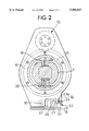
- FIG. 2 is a section taken substantially along the line II--II in FIG. 1.
- FIG. 1 A portion of a self-loading controlled deflection roll 1 is shown in FIG. 1.
- the roll 1 is a driven roll, and the driven end is shown, however, it will be understood that the principles of the present invention apply equally to non-driven rolls, and the locating link disclosed and claimed herein can be used to equal advantage at a non-driven end of a roll.
- the controlled deflection roll 1 has a roll shell 2 which is entirely hydrostatically supported by a loading shoe 3 and side shoes 9 (only one side shoe is shown in FIG. 1).
- the example of the roll 1 shown in FIG. 1 employs outboard shoes 18 and 20, described in more detail below, for controlling the deflection of the roll shell 2, and thus the loading shoe 3 functions solely to load the shell 2 against an opposing roll (not shown) which will form a nip with the roll 1.
- the use of the outboard shoes 18 and 20 permits the loading shoe 3 to extend substantially the entire width of the nip loading zone, which is the zone in which pressure is exerted on the sheet as it travels through the nip. As shown in phantom lines, however, multiple, smaller shoes 3a can be used to load the roll shell 2.
- the shoes 3, 9 (and, if present 3a) are mounted in bores in a central portion of a center shaft 4.
- the respective shoes are fed by hydraulic lines in the center shaft 4, which are connected to a hydraulic fluid delivery system (not shown).
- Each shoe also contains hydrostatic bearing surfaces, which are fed with hydraulic fluid by bores extending through the respective shoes.
- the roll shell 2 is thus completely radially hydrostatically supported on a thin film of hydraulic fluid.
- the center shaft 4 has a stub arbor 5 which extends through a bearing assembly 6, preferably comprising a spherical bushing as shown in FIG. 1, supported on a stand 7 mounted on the floor 8, or some other suitable fixed supporting surface.
- a bearing assembly 6 preferably comprising a spherical bushing as shown in FIG. 1, supported on a stand 7 mounted on the floor 8, or some other suitable fixed supporting surface.
- the roll shell 2 is bolted to an annular head flange 10 (the opposite end of the roll shell 2 being similarly bolted to a head flange at the opposite end, which is connected to a bearing ring 31 which is part of a bearing assembly for the opposite end of the roll 1).
- the head flange 10 is bolted to a gear 11 which rotates on tapered bearings 16.
- the gear 11 is driven by a drive assembly 12, which includes a drive gear 14 contained in a housing 13, the drive gear 14 being rotated by a shaft 15 connected to a prime mover (not shown).
- the roll 1 is also provided with barrier seals 17, which are similarly fed by hydraulic lines extending through the center shaft 4 and connected to the aforementioned fluid delivery system. It is contemplated that plain seals, which do not require fluid, can also be used.
- control of the crown of the roll shell 2 is accomplished in the example shown in FIG. 1 by outboard shoes 18 and 20, which are respectively received in bores 19 and 21 in the center shaft 4.
- the bores 19 and 21 are fed with hydraulic fluid via conduits in the center shaft 4, also connected to the aforementioned hydraulic fluid delivery system.
- the outboard shoes 18 and 20 each have hydrostatic bearing surfaces bearing against the inside surface of the head flange 10.
- the head flange 10 transmits the forces generated by the shoes 18 and 20 to the roll shell 2, so as to control the deflection thereof.
- the roll shell 2 is thus completely hydrostatically radially supported, and since such hydrostatic support is, by its nature, substantially frictionless, the aforementioned bearing pads which bear against the inner surface of the rolls shell 2 (or the inner surface of the head flange 10) will not be capable of positioning the roll shell 2 axially, nor will such hydrostatic bearings provide any opposing force to any axial thrust load which may be present.
- a mechanical locating link 23 is provided, which mechanically axially fixes one end of the roll shell 2.
- the locating link 23 is completely mechanical and thus does not contribute to the complexity of the hydraulic system.
- the locating link 23 is disposed completely externally of the roll shell 2, and thus is easily accessible for maintenance and adjustment.
- the mechanical locating link 23 includes a shaft 23a received in collars 23b and 23c at its opposite ends.
- the ends of the shaft 23a may be threaded, and the bores in the collars 23b and 23c in which those ends are received may be threaded in a complementary manner, so that when the shaft 23a is rotated the overall length of the shaft and collars combination can be adjusted axially.
- the collar 23b is received between downwardly extending flanges 22, which are attached to the housing 13 (i.e. gear box) of the roll 1.
- the collar 23b is held between the flanges 22 by a pin 24.
- the collar 23c is held between upwardly extending flanges 29, which are rigidly attached to the floor 8.
- the collar 23c is held between the flanges 29 by a pin 28. Since the flanges 29 are rigidly attached to the floor 8, the locating link 23 rigidly fixes the end of the roll shell 2 at which the link 23 is disposed relative to the floor 8.
- the opposite end of the roll shell 2 is not similarly axially fixed, and thus is free to float to accommodate thermal expansion of the roll shell 2.
- the locating link 23 may, however, be disposed at the opposite end of the roll shell 2, at the bearing box located at that opposite end, instead of at the driven end of the roll 1 as shown in FIG. 1.
- the bearing box (not shown) essentially corresponds to gear box 13, but without the gears. Only one end of the roll shell 2 will, however, be axially fixed, i.e., a locating link will never be used at both ends of a roll simultaneously.
- a mechanical oscillator 32 can be provided, in driving connection with the locating link 23, so as to mechanically oscillate the locating link 23 during operation of the roll 1.
- a mechanical oscillator 32 can be provided, in driving connection with the locating link 23, so as to mechanically oscillate the locating link 23 during operation of the roll 1.
- torque link 27 is used to oppose torque generated by gear drive forces on the gear box in order to hold the gear box stationary such that it will not rotate about the axis of the roll.
- the torque link 27 is held by a pin 26 between upwardly extending flanges 25, which are rigidly attached to the floor 8, and the opposite end of the torque link 27 is pinned by a pin 30 to flanges which are a part of the surrounding structure of the roll 1.
- a similar torque link 27 is disposed at the opposite end of the roll 1.
- the locating link 23 can be seen in end view in FIG. 2.
- link 23 for locating the roll shell could be disposed within the roll shell, such as, for example, by extending flanges 22 upwardly to within the apparatus instead of downwardly as shown in FIG. 1. This would change the location of link 23 slightly, but the positioning operation of the apparatus would be the same as described above.
Landscapes
- Physics & Mathematics (AREA)
- Fluid Mechanics (AREA)
- Engineering & Computer Science (AREA)
- General Engineering & Computer Science (AREA)
- Mechanical Engineering (AREA)
- Paper (AREA)
- Rolls And Other Rotary Bodies (AREA)
- Registering, Tensioning, Guiding Webs, And Rollers Therefor (AREA)
Priority Applications (1)
| Application Number | Priority Date | Filing Date | Title |
|---|---|---|---|
| US08/980,191 US5984847A (en) | 1994-08-16 | 1997-11-26 | Self loading controlled deflection roll |
Applications Claiming Priority (2)
| Application Number | Priority Date | Filing Date | Title |
|---|---|---|---|
| US29138194A | 1994-08-16 | 1994-08-16 | |
| US08/980,191 US5984847A (en) | 1994-08-16 | 1997-11-26 | Self loading controlled deflection roll |
Related Parent Applications (1)
| Application Number | Title | Priority Date | Filing Date |
|---|---|---|---|
| US29138194A Continuation | 1994-08-16 | 1994-08-16 |
Publications (1)
| Publication Number | Publication Date |
|---|---|
| US5984847A true US5984847A (en) | 1999-11-16 |
Family
ID=23120076
Family Applications (1)
| Application Number | Title | Priority Date | Filing Date |
|---|---|---|---|
| US08/980,191 Expired - Fee Related US5984847A (en) | 1994-08-16 | 1997-11-26 | Self loading controlled deflection roll |
Country Status (9)
| Country | Link |
|---|---|
| US (1) | US5984847A (fr) |
| EP (1) | EP0786032B1 (fr) |
| JP (1) | JP2814412B2 (fr) |
| KR (1) | KR100369491B1 (fr) |
| BR (1) | BR9508594A (fr) |
| CA (1) | CA2197663C (fr) |
| DE (2) | DE69505555T2 (fr) |
| FI (1) | FI116306B (fr) |
| WO (1) | WO1996005368A2 (fr) |
Cited By (2)
| Publication number | Priority date | Publication date | Assignee | Title |
|---|---|---|---|---|
| US6524228B1 (en) * | 1998-07-24 | 2003-02-25 | Eduard Kusters Maschinenfabrik Gmbh & Co. Kg | Deflection roller with mechanical stop |
| US6663549B2 (en) * | 2000-10-12 | 2003-12-16 | Voith Paper Patent Gmbh | Deflection controlled roll with force generating device |
Families Citing this family (2)
| Publication number | Priority date | Publication date | Assignee | Title |
|---|---|---|---|---|
| US5885201A (en) * | 1997-07-24 | 1999-03-23 | Beloit Technologies, Inc. | Non-self loading controlled deflection roll |
| GB0112321D0 (en) * | 2001-05-21 | 2001-07-11 | Prec Actuation Systems Ltd | Control system |
Citations (23)
| Publication number | Priority date | Publication date | Assignee | Title |
|---|---|---|---|---|
| DE1016116B (de) * | 1953-10-31 | 1957-09-19 | Millspaugh Ltd | Walzenschaber fuer Papiermaschinen od. dgl. |
| US3340140A (en) * | 1963-09-06 | 1967-09-05 | Millspaugh Ltd | Press and felt sections of papermaking machines |
| US3565759A (en) * | 1968-06-10 | 1971-02-23 | Black Clawson Co | Paper machine press |
| US3838480A (en) * | 1972-06-21 | 1974-10-01 | Mount Hope Machinery Ltd | Adjustable curvature axle assembly for expander rolls and the like |
| US4000979A (en) * | 1975-02-18 | 1977-01-04 | Escher Wyss Limited | Roll for a rolling mill |
| US4520723A (en) * | 1983-07-14 | 1985-06-04 | Kleinewefers Gmbh | Pressure roll for use in calenders or the like |
| US4657637A (en) * | 1984-09-17 | 1987-04-14 | Sunds Defibrator Aktiebolag | Pulp treatment apparatus having lowerable vacuum containers to facilitate removal thereof |
| US4821384A (en) * | 1987-11-05 | 1989-04-18 | Beloit Corporation | Self-loading controlled deflection roll |
| US4827584A (en) * | 1986-08-20 | 1989-05-09 | Kleinewefers Gmbh | Pressure roll for use in calenders |
| US4837907A (en) * | 1987-08-20 | 1989-06-13 | Beloit Corporation | Self-loading controlled deflection roll |
| US4888096A (en) * | 1987-12-02 | 1989-12-19 | Inotech Process Ltd. | Roll press for removing water from a web of paper using solid grooved roll and compressed air |
| US4891874A (en) * | 1987-08-20 | 1990-01-09 | Beloit Corporation | Self loading controlled deflection roll |
| JPH0267765A (ja) * | 1988-09-01 | 1990-03-07 | Nec Corp | 半導体装置の製造方法 |
| JPH0361044A (ja) * | 1989-07-31 | 1991-03-15 | Sumitomo Heavy Ind Ltd | 印刷機の刷版取付装置 |
| US5021124A (en) * | 1989-02-15 | 1991-06-04 | Valmet Paper Machinery Inc. | Double doctor for a paper machine and method for adjustment of same |
| US5060357A (en) * | 1990-06-21 | 1991-10-29 | Beloit Corporation | Self-loading controlled deflection roll |
| US5111563A (en) * | 1991-02-04 | 1992-05-12 | Beloit Corporation | Self-loading, controlled deflection roll |
| US5127141A (en) * | 1987-03-27 | 1992-07-07 | Beloit Corporation | Self-loading controlled deflection roll |
| US5193258A (en) * | 1991-11-15 | 1993-03-16 | Beloit Technologies, Inc. | Self-loading controlled deflection roll |
| US5242361A (en) * | 1992-11-17 | 1993-09-07 | Beloit Technologies, Inc. | Roller mechanism for axially locating the shell of a self-loading controlled deflection roll |
| JPH05507130A (ja) * | 1990-05-08 | 1993-10-14 | ヴァルメト カルルスタッド アクチボラグ | プレスロール |
| US5273626A (en) * | 1991-01-07 | 1993-12-28 | Valmet Paper Machinery Inc. | Adjustable-crown roll |
| JPH10507515A (ja) * | 1994-07-13 | 1998-07-21 | アイ−スタット コーポレーション | 気体濃度測定の方法及びそれを実施するための微細加工検出装置 |
-
1995
- 1995-08-10 DE DE69505555T patent/DE69505555T2/de not_active Expired - Fee Related
- 1995-08-10 EP EP95930813A patent/EP0786032B1/fr not_active Expired - Lifetime
- 1995-08-10 KR KR1019970700977A patent/KR100369491B1/ko not_active Expired - Fee Related
- 1995-08-10 DE DE0786032T patent/DE786032T1/de active Pending
- 1995-08-10 CA CA002197663A patent/CA2197663C/fr not_active Expired - Fee Related
- 1995-08-10 BR BR9508594A patent/BR9508594A/pt not_active IP Right Cessation
- 1995-08-10 WO PCT/US1995/010217 patent/WO1996005368A2/fr not_active Ceased
- 1995-08-10 JP JP8507515A patent/JP2814412B2/ja not_active Expired - Fee Related
-
1997
- 1997-02-14 FI FI970635A patent/FI116306B/fi active IP Right Grant
- 1997-11-26 US US08/980,191 patent/US5984847A/en not_active Expired - Fee Related
Patent Citations (23)
| Publication number | Priority date | Publication date | Assignee | Title |
|---|---|---|---|---|
| DE1016116B (de) * | 1953-10-31 | 1957-09-19 | Millspaugh Ltd | Walzenschaber fuer Papiermaschinen od. dgl. |
| US3340140A (en) * | 1963-09-06 | 1967-09-05 | Millspaugh Ltd | Press and felt sections of papermaking machines |
| US3565759A (en) * | 1968-06-10 | 1971-02-23 | Black Clawson Co | Paper machine press |
| US3838480A (en) * | 1972-06-21 | 1974-10-01 | Mount Hope Machinery Ltd | Adjustable curvature axle assembly for expander rolls and the like |
| US4000979A (en) * | 1975-02-18 | 1977-01-04 | Escher Wyss Limited | Roll for a rolling mill |
| US4520723A (en) * | 1983-07-14 | 1985-06-04 | Kleinewefers Gmbh | Pressure roll for use in calenders or the like |
| US4657637A (en) * | 1984-09-17 | 1987-04-14 | Sunds Defibrator Aktiebolag | Pulp treatment apparatus having lowerable vacuum containers to facilitate removal thereof |
| US4827584A (en) * | 1986-08-20 | 1989-05-09 | Kleinewefers Gmbh | Pressure roll for use in calenders |
| US5127141A (en) * | 1987-03-27 | 1992-07-07 | Beloit Corporation | Self-loading controlled deflection roll |
| US4837907A (en) * | 1987-08-20 | 1989-06-13 | Beloit Corporation | Self-loading controlled deflection roll |
| US4891874A (en) * | 1987-08-20 | 1990-01-09 | Beloit Corporation | Self loading controlled deflection roll |
| US4821384A (en) * | 1987-11-05 | 1989-04-18 | Beloit Corporation | Self-loading controlled deflection roll |
| US4888096A (en) * | 1987-12-02 | 1989-12-19 | Inotech Process Ltd. | Roll press for removing water from a web of paper using solid grooved roll and compressed air |
| JPH0267765A (ja) * | 1988-09-01 | 1990-03-07 | Nec Corp | 半導体装置の製造方法 |
| US5021124A (en) * | 1989-02-15 | 1991-06-04 | Valmet Paper Machinery Inc. | Double doctor for a paper machine and method for adjustment of same |
| JPH0361044A (ja) * | 1989-07-31 | 1991-03-15 | Sumitomo Heavy Ind Ltd | 印刷機の刷版取付装置 |
| JPH05507130A (ja) * | 1990-05-08 | 1993-10-14 | ヴァルメト カルルスタッド アクチボラグ | プレスロール |
| US5060357A (en) * | 1990-06-21 | 1991-10-29 | Beloit Corporation | Self-loading controlled deflection roll |
| US5273626A (en) * | 1991-01-07 | 1993-12-28 | Valmet Paper Machinery Inc. | Adjustable-crown roll |
| US5111563A (en) * | 1991-02-04 | 1992-05-12 | Beloit Corporation | Self-loading, controlled deflection roll |
| US5193258A (en) * | 1991-11-15 | 1993-03-16 | Beloit Technologies, Inc. | Self-loading controlled deflection roll |
| US5242361A (en) * | 1992-11-17 | 1993-09-07 | Beloit Technologies, Inc. | Roller mechanism for axially locating the shell of a self-loading controlled deflection roll |
| JPH10507515A (ja) * | 1994-07-13 | 1998-07-21 | アイ−スタット コーポレーション | 気体濃度測定の方法及びそれを実施するための微細加工検出装置 |
Cited By (2)
| Publication number | Priority date | Publication date | Assignee | Title |
|---|---|---|---|---|
| US6524228B1 (en) * | 1998-07-24 | 2003-02-25 | Eduard Kusters Maschinenfabrik Gmbh & Co. Kg | Deflection roller with mechanical stop |
| US6663549B2 (en) * | 2000-10-12 | 2003-12-16 | Voith Paper Patent Gmbh | Deflection controlled roll with force generating device |
Also Published As
| Publication number | Publication date |
|---|---|
| EP0786032B1 (fr) | 1998-10-21 |
| DE69505555D1 (de) | 1998-11-26 |
| KR100369491B1 (ko) | 2003-08-19 |
| FI970635A7 (fi) | 1997-02-14 |
| KR970704939A (ko) | 1997-09-06 |
| BR9508594A (pt) | 1997-11-11 |
| FI970635A0 (fi) | 1997-02-14 |
| EP0786032A2 (fr) | 1997-07-30 |
| WO1996005368A2 (fr) | 1996-02-22 |
| CA2197663C (fr) | 2001-01-30 |
| DE786032T1 (de) | 1998-01-15 |
| CA2197663A1 (fr) | 1996-02-22 |
| FI116306B (fi) | 2005-10-31 |
| JP2814412B2 (ja) | 1998-10-22 |
| JPH09508677A (ja) | 1997-09-02 |
| WO1996005368A3 (fr) | 1996-06-06 |
| DE69505555T2 (de) | 1999-06-17 |
Similar Documents
| Publication | Publication Date | Title |
|---|---|---|
| US3276102A (en) | Adjustable crown roll | |
| US4414890A (en) | Press roll with adjustable flexion | |
| US4639990A (en) | Roll for treating webs, preferably webs of paper | |
| US3430319A (en) | Nondeflection support for web carrying roll | |
| CA1324521C (fr) | Rouleau | |
| US5984847A (en) | Self loading controlled deflection roll | |
| US5495798A (en) | Adjustable-crown roll | |
| JPH02102914A (ja) | セルフローデイング偏位制御ロール | |
| US5010633A (en) | Controlled deflection roll with heat barrier | |
| US4995147A (en) | Roll having improved transverse end seals | |
| US5843282A (en) | Heated roll bearing system | |
| US5788619A (en) | Hydrostatic self-loading controlled deflection roll | |
| US6346066B1 (en) | Tubular roll provided with hydraulically loaded glide bearings | |
| EP1475165B1 (fr) | Palier triple des abres d'un laminoir en porte-à-faux | |
| US5474656A (en) | Equal lift self-loading controlled deflection roll and method for operating same | |
| US5865716A (en) | Method and apparatus for regulating the temperature in end areas of a roll mantle of a variable-crown roll having glide bearings | |
| US5885201A (en) | Non-self loading controlled deflection roll | |
| US4891874A (en) | Self loading controlled deflection roll | |
| JPS6352157B2 (fr) | ||
| US3418703A (en) | Antideflection roll with non-rotating beam and lever supports | |
| US3481016A (en) | Driven controlled deflection roll | |
| FI131016B1 (en) | Motor unit for a fabric feeding unit in a fiber web machine and fabric feeding unit for a fiber web machine |
Legal Events
| Date | Code | Title | Description |
|---|---|---|---|
| FEPP | Fee payment procedure |
Free format text: PAYOR NUMBER ASSIGNED (ORIGINAL EVENT CODE: ASPN); ENTITY STATUS OF PATENT OWNER: LARGE ENTITY |
|
| AS | Assignment |
Owner name: METSO PAPER INC., FINLAND Free format text: ASSIGNMENT OF ASSIGNORS INTEREST;ASSIGNOR:BELOIT TECHNOLOGIES, INC.;REEL/FRAME:012119/0182 Effective date: 20010816 Owner name: MITSUBISHI HEAVY INDUSTRIES, LTD., JAPAN Free format text: ASSIGNMENT OF ASSIGNORS INTEREST;ASSIGNOR:BELOIT TECHNOLOGIES, INC.;REEL/FRAME:012119/0182 Effective date: 20010816 |
|
| FPAY | Fee payment |
Year of fee payment: 4 |
|
| FPAY | Fee payment |
Year of fee payment: 8 |
|
| REMI | Maintenance fee reminder mailed | ||
| LAPS | Lapse for failure to pay maintenance fees | ||
| STCH | Information on status: patent discontinuation |
Free format text: PATENT EXPIRED DUE TO NONPAYMENT OF MAINTENANCE FEES UNDER 37 CFR 1.362 |
|
| FP | Lapsed due to failure to pay maintenance fee |
Effective date: 20111116 |
|
| AS | Assignment |
Owner name: VALMET TECHNOLOGIES, INC., FINLAND Free format text: CHANGE OF NAME;ASSIGNOR:METSO PAPER, INC.;REEL/FRAME:032551/0426 Effective date: 20131212 |