US5994909A - Robotic twin probe for measurement on printed circuit boards and electrical and electronic assemblies - Google Patents
Robotic twin probe for measurement on printed circuit boards and electrical and electronic assemblies Download PDFInfo
- Publication number
- US5994909A US5994909A US08/958,747 US95874797A US5994909A US 5994909 A US5994909 A US 5994909A US 95874797 A US95874797 A US 95874797A US 5994909 A US5994909 A US 5994909A
- Authority
- US
- United States
- Prior art keywords
- probe
- control signal
- lead
- responsive
- circuitry
- Prior art date
- Legal status (The legal status is an assumption and is not a legal conclusion. Google has not performed a legal analysis and makes no representation as to the accuracy of the status listed.)
- Expired - Fee Related
Links
Images




Classifications
-
- G—PHYSICS
- G01—MEASURING; TESTING
- G01R—MEASURING ELECTRIC VARIABLES; MEASURING MAGNETIC VARIABLES
- G01R31/00—Arrangements for testing electric properties; Arrangements for locating electric faults; Arrangements for electrical testing characterised by what is being tested not provided for elsewhere
- G01R31/28—Testing of electronic circuits, e.g. by signal tracer
- G01R31/2851—Testing of integrated circuits [IC]
- G01R31/2886—Features relating to contacting the IC under test, e.g. probe heads; chucks
- G01R31/2887—Features relating to contacting the IC under test, e.g. probe heads; chucks involving moving the probe head or the IC under test; docking stations
Definitions
- the invention pertains to systems for testing circuitry and, in particular, for testing circuitry with the use of robotics to position probe leads through a polar coordinate positioning technique.
- circuitry on a board poses a major challenge to manual testing.
- High circuit density may require the test engineers to use microscopes to manually place the probe leads on the board. Small pins may need to be soldered to the probe leads for finer precision placement on the board.
- Awkward mechanical probe holders are often required to ensure that the probe leads do not move from their test points once they are so painstakingly positioned.
- circuit board test results often contain errors due to corresponding probe misalignment.
- Manual testing also requires that trained engineers be present to perform the tests. This requirement drives up the cost of the testing. It also hinders the effective use of remote testing because test engineers must be on-site with the test equipment. The test engineers cannot direct placement of the probe leads and view test results from a remote location.
- the invention overcomes the problems outlined above by providing an automated system and method for testing circuitry.
- the invention performs testing quickly and accurately, and advantageously allows remote testing in some embodiments.
- the invention utilizes radial arm robotics to place probe leads at selected points on a circuit board with extreme precision.
- the robotic placement of twin probe leads on the circuitry allows the leads to be as short as possible and minimizes the impedance and inductance associated with the probe leads.
- System reliability is enhanced by the rotational/radial positioning of the probe leads, as opposed to X-Y positioning, because the bobbin leads fatigue less and last longer under repetitive motion strain.
- the robotics comprise motors and associated control software.
- the control software can process user input and direct the motors to place the probe leads.
- the control software also directs the probe to perform the testing and provides the test results to the user.
- the motors utilize a polar coordinate positioning system.
- a rotational motor positions a second probe lead in a rotational direction relative to a first probe lead.
- a radial motor positions the second probe lead in a radial direction relative to the first probe lead.
- a Z-direction motor positions both probe leads in a Z-direction relative to the circuitry and engages the probe leads with the circuitry.
- the invention provides for remote testing of printed circuit boards.
- a remote terminal is used to display a diagram of the circuitry to the user. The user may then simply point and click probe placement points and selected tests on the remote terminal display.
- control software directs the motors to position the probe leads relative to one another and to the circuit board. The control software then directs the probe to conduct the tests. Finally, the control software displays the test results to the user at the remote terminal display.
- the invention performs automated testing of complex circuitry. Using the polar coordinate positioning technique, the invention is able to place probe leads at selected probe placement points with extreme precision. In some embodiments, the probe leads are placed within 0.01 inches of the selected probe placement points, and in other embodiments, the probe leads are placed within 0.001 inches of the selected probe placement points. Automation also allows the testing to be performed quickly and accurately without the problems associated with manual testing.
- FIG. 1 is a block diagram of a version of the invention.
- FIG. 2 is a sketch of a version of the invention.
- FIG. 3 is a block diagram of a remote terminal display in a version of the invention.
- FIG. 4 is a schematic diagram of a circuit board in a version of the invention.
- FIG. 5 is a flow diagram for control software in a version of the invention.
- FIG. 6 is a flow diagram for a probe placement routine in a version of the invention.
- FIG. 1 is a block diagram of a version of the invention for testing circuitry 140 with the probe leads 122 and 123.
- the surface of the circuitry 140 lies in the X-Y plane of a Cartesian reference system and in the rotational/radial plane of a polar reference system.
- the surface of the circuitry 140 is perpendicular to the Z-axis of both reference systems.
- the encoder 105 and the rotational motor 111 comprise a rotational positioning system that positions the probe lead 123 in a rotational direction relative to the probe lead 122 responsive to a rotational control signal from the controller 100.
- the encoder 106 and the radial motor 112 comprise a radial positioning system that positions the probe lead 123 in a radial direction relative to the probe lead 122 responsive to a radial control signal from the controller 100.
- the encoder 104 and the Z-direction motor 110 comprise a Z-direction positioning system that positions the probe lead 122 and the probe lead 123 in a Z-direction relative to the circuitry 140 responsive to a Z-direction control signal from the controller 100.
- the probe 120 conducts testing responsive to a probe control signal from the controller 100.
- the controller 100 generates the control signals responsive to user input.
- the controller 100 is coupled to a remote terminal 102 by a connection 130.
- the controller 100 is respectively coupled to corresponding encoders 104, 105, and 106 by connections 131, 132, and 133.
- the controller 100 is coupled to instruments 142 by a connection 134, and the instruments 142 are coupled to a probe 120 by a connection 135.
- the controller 100 is also coupled to an X-Y table 103 by a connection 136.
- the connection 128 operationally couples the probe lead 123 to the probe 120.
- the X-Y table 103 is coupled to the Z-direction motor 110.
- the encoders 104-106 are respectively coupled to motors 110, 111, and 112.
- the Z-direction motor 110 is coupled to the rotational motor 111.
- the rotational motor 111 includes shaft 114 and is coupled to the radial motor 112.
- the probe lead 122 is co-axial with the shaft 114.
- Radial motor 112 includes carriage 116, and the carriage 116 is coupled to probe lead 123.
- the radial motor 112 carries the probe lead 123.
- the probe 120 has a probe lead 122 and is centrally coupled to the interior of the shaft 114.
- the probe lead 122 is coextensive with the rotational axis of the shaft 114.
- the circuitry 140 is shown under the probe leads 122 and 123.
- the circuitry 140 could be any circuitry that can be tested with a probe.
- One example of such circuitry is a printed circuit board. Printed circuit boards are commonly found in computers and other electronic devices.
- Some examples of testing for the circuitry 140 are: automated hardware design verification, analog simulator verification, SPICE model validation, IBIS model validation, automated design surveys, time domain reflectrometry, differential, fault injection, and signal integrity.
- U.S. Pat. No. 5,550,844 discloses a fault injection test circuit for testing printed circuit boards in a fully powered-up, operational condition.
- U.S. Pat. No. 5,550,844 is hereby incorporated by reference into this application.
- SPICE and IBIS systems are well known technologies for modeling circuit boards. These systems have the capability to accept test data in comparision with an electronic model.
- the invention interacts with this conventional data transfer format.
- SPICE model verification the parametric results of the prototype design are electrically centered to assure that the prototype is within the margins specified by the simulation results.
- Probe 120 and associated probe leads 122-123 could comprise any device that is capable of testing circuitry. Some examples of such probes are active FET probes, differential probes, time domain reflectrometry probes, RF probes, and shorting probes. If an FET probe is used, it is preferred that the probe lead 122 represent the measuring tip and the probe lead 123 represent the reference lead.
- a suitable active FET probe is the 54701A provided by Hewlett Packard.
- a suitable differential probe is the 1141A provided by Hewlett Packard.
- a suitable time domain reflectrometry probe is the P6150 provided by Tektronix.
- a suitable RF probe is the 85024A provided by Hewlett Packard.
- the probe leads should remain as short as possible to minimize inductance and capacitance.
- the probe leads 122-123 are comprised of pogo pins. Pogo pins allow the probe leads to remain firmly pressed against the circuitry 140 after they are engaged.
- Connection 128 is typically a bar and wiper comprised of a highly conductive material such as gold or aluminum, but it could be any control coupling that allows the probe leads 122-123 to interact.
- the X-Y table 103 is coupled to the Z-direction motor 110 and comprises an X-Y direction positioning system that positions the probe leads 122-123 in an X-Y direction relative to the circuitry responsive to an X-Y control signal from the controller 100.
- the rotational motor 111 rotates the radial motor 112 around the shaft 114 to concurrently rotate the probe lead 123 with respect to the probe lead 122.
- the radial motor 112 moves the probe lead 123 in a radial direction relative the probe lead 122 and the shaft 114.
- the radial direction means directed toward or away from the central axis of the shaft 114, much like a spoke on a wheel.
- the Z-direction motor moves the probe leads 122-123 in a Z-direction relative to the rotational and radial directions.
- the Z-direction motor 110 moves the rotational motor 111 up or down in a direction parallel to the central axis of the shaft 114 to engage the probe leads 122-123 with the circuitry 140.
- the X-Y table 103 is a conventional device known to those skilled in the art.
- a suitable rotational motor 111 is the 118733 model provided by Maxon of Kansas City, Mo.
- a suitable radial motor 112 is the S372-1A/T provided by Electrocraft of Clearwater, Fla.
- a suitable Z-direction motor 111 is the S240 model provided by Electrocraft.
- the encoders 104-106 control the action of their associated motors 110-112 in response to control signals from the controller 100.
- the encoder 104 responds to a Z-direction control signal.
- the encoder 105 responds to a rotational control signal.
- the encoder 106 responds to a radial control signal.
- a suitable encoder 104 is the RM21-10000-8-5VLD provided by Renco.
- a suitable encoder 105 is the RM15-100-5-5VLD provided by Renco.
- a suitable encoder 106 is the T.sub. -- -- E.15 provided by Maxon.
- the encoders 104-106 could be incorporated into their respective motors 110-112 or incorporated into the controller 100.
- the controller 100 generates and provides control signals in response to user input.
- the control signals cause the X-Y table to position the probe leads 122-123 relative to the circuitry 140.
- the control signals cause the motors 110-112 to properly position the probe leads 122-123 relative to each other and the circuitry 140.
- the control signals cause the probe 120 to perform the desired testing.
- the controller 100 could be a personal computer that is programmed in accord with the invention.
- the connections 130-136 could be any control links that are capable of transporting the control signals. Typically, connections 131-136 are wires. Those skilled in the art are familiar with various ways to provide connection 130, such as an encrypted internet session, data link, or modem connection.
- the remote terminal 102 collects user inputs and provides them to the controller 100.
- the remote terminal 102 could be a personal computer with display that is programmed in accord with the invention.
- the remote terminal 102 displays a CAD map of the circuitry 140 and a list of tests.
- the remote terminal 102 then allows the user to select the desired probe placement points and tests by pointing and clicking on the display with a mouse.
- the user input is then provided to the controller 100 over the connection 130.
- the remote terminal 102 can also display test results.
- One example of a display format for test results is the use of waveforms.
- the instruments 142 are conventional devices for use with probes. Some examples of the instruments 142 are oscilloscopes and spectrum analyzers. Those skilled in the art will appreciate the use of instruments 142 in the context of the invention.
- an additional rotational motor/encoder and an additional radial motor/encoder could be could be coupled to the Z-direction motor 110 to position a third probe lead. Depiction of this arrangement is not shown on FIG. 1 for purposes of clarity.
- the third probe lead could be used to detect a triggering event occurring in the circuitry, and in response to the triggering event, to perform a test with the other two probe leads. Some examples of triggering events would be voltage thresholds, slopes, pulse widths, and series pulse events. Some examples of tests based on triggering events are fault injection and signal capture.
- FIG. 2 depicts a sketch of a version of the invention. Some of the same reference numbers are carried over from FIG. 1 and represent the same device. Shown are: rotational motor 105 and encoder 111, radial motor 106 and encoder 112, shaft 114, carriage 116, and probe 120 and associated probe leads 122-123. Also shown on FIG. 2 are a camera 200 and associated mounting 202, bearing and attachment block 204, and single axis mechanism 206. Camera 200 is used to view the circuitry under test and provide a fixed reference point. Mounting 202 and bearing and attachment block 204 are used to mount the rotational and radial positioning systems to the X, Y, and Z positioning systems.
- the controller 100 receives user input indicating the selected tests and probe placement points.
- the input could be received from the remote terminal 102 over the connection 130 or input directly into controller 100.
- the controller 100 processes this input, along with a CAD file for the circuitry 140.
- the controller generates an X-Y control signal to cause the X-Y table 103 to position the probe leads 122-123 relative to the circuitry 140.
- the controller 100 then generates control signals for the encoders 104-106.
- the controller 100 provides the encoder 104 with a Z-direction control signal over the connection 131.
- the controller 100 provides the encoder 105 with a rotational control signal over the connection 132.
- the controller 100 provides the encoder 106 with a radial control signal over the connection 133.
- the encoders 104-106 direct their respective motors 110-112 to position the probe leads 122-123.
- the rotational motor 111 rotates the probe lead 123 relative to the probe lead 122.
- the radial motor 111 moves the probe lead 123 in a radial direction relative to the probe lead 122.
- the Z-direction motor 110 moves both of the probe leads 122-123 down to engage the circuitry 140.
- the controller 100 interfaces with the probe 120 through the instruments 142 to conduct testing and obtain test results.
- the probe control signals that initiate the tests and the subsequent test results are carried over connections 134-135.
- the controller 100 can then provide the results to the remote terminal 102 over connection 130 for subsequent display to the user.
- FIG. 3 depicts a remote terminal display for some embodiments of the invention.
- the remote terminal 102 includes a display 300.
- the display 300 shows a CAD map of the circuitry 140 including a circuit 302.
- the display also shows a list of selected tests. Those skilled in the art can appreciate that their are any number of circuits and tests could be shown on the display 300.
- the user points and clicks selected probe placement points 304-305 on the circuit 302 and the selected tests from the list.
- the remote terminal 102 then provides these selections to the controller 100 over the connection 130. After the testing, the remote terminal 100 receives the test results from the controller 100 over connection 130 and displays them to the user.
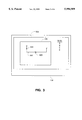
- FIG. 4 depicts the polar coordinate technique used by the invention to position the probe leads 122-123.
- the circuitry 140 is shown with the selected probe placement points 304-305 marked with an "x" on the circuit 302.
- the probe lead 122 is first aligned with the probe placement point 304.
- the probe lead 123 is rotated by the rotational angle 400, and then the probe lead 123 is moved in a radial direction toward probe placement point 304 by a distance 402.
- the probe lead 123 is aligned with probe placement point 305.
- Both probe leads 122-123 would be engaged with their respective probe placement points 304-305 by moving the probe leads 122-123 into the drawing in the Z-direction.
- FIG. 5 depicts a flow diagram of the control software in a version of the invention.
- the software collects a placement point for the first probe lead (X1,Y1), a placement point for the second probe lead (X2,Y2), and the test for these placement points. If more probe positions or tests are desired by the user at step 502, the software collects these (X1,Y1) and (X2,Y2) placement points or tests until all probe placement points and tests are collected.
- the first (X1,Y1) and (X2,Y2) placement points are sent to a probe placement routine.
- the software sends an "engage Z" command to the placement routine at step 505.
- the software commands the circuitry to operate and commands the probe to take measurements for the selected tests at step 507.
- test results are received from the probe at step 508, the software commands the circuitry to stop operating at step 509.
- the control software determines if there are more test positions at step 510. If there are no more test positions, the measurements are processed at step 511 and the process ends. If there are more test positions at step 510, the control software returns to step 503, and the (X1,Y1) and (X2,Y2) placement points for the next position are sent to the probe placement routine. Steps 503-510 repeat until all positions are tested.
- FIG. 6 depicts a flow diagram for a placement routine in a version of the invention.
- the placement routine is a routine in the control software that receives probe placement points and directs the movement of the motors.
- the routine starts at step 601 when the (X1,Y1) and (X2,Y2) placement points are received from the control software.
- the routine calculates the rotational movement and the radial movement from the (X1,Y1) placement point to the (X2,Y2) placement point at step 602.
- the routine commands the Z motor to retract the probe leads at step 603.
- the routine commands the X-Y table to move probe lead #1 to (X1,Y1) at step 604.
- the routine commands the rotational motor and the radial motor to move probe lead #2 to (X2,Y2) at step 605.
- the routine sends an "in position” signal to the control software at step 606.
- the routine commands the Z motor to engage the probe leads with the circuitry at step 608.
- the routine sends an "engaged” signal to the control software at step 609, and the routine returns to step 601 for the next set of placement points.
- the invention provides for the accurate placement of twin probe leads to facilitate circuitry testing.
- the robotic placement of twin probe leads minimizes the length of the leads, and as a result, minimizes the inductance and impedance that degrade testing performance.
- the use of robotics allows for repeated precision placement that is faster than manual placement and that avoids human error.
- the invention is capable of testing fully powered-up and operational circuit boards.
Landscapes
- Engineering & Computer Science (AREA)
- Computer Hardware Design (AREA)
- Microelectronics & Electronic Packaging (AREA)
- General Engineering & Computer Science (AREA)
- Physics & Mathematics (AREA)
- General Physics & Mathematics (AREA)
- Tests Of Electronic Circuits (AREA)
- Measuring Leads Or Probes (AREA)
Priority Applications (7)
| Application Number | Priority Date | Filing Date | Title |
|---|---|---|---|
| US08/958,747 US5994909A (en) | 1997-08-25 | 1997-10-31 | Robotic twin probe for measurement on printed circuit boards and electrical and electronic assemblies |
| CA002301604A CA2301604A1 (en) | 1997-08-25 | 1998-08-21 | Robotic twin probe for measurement on printed circuit boards and electrical and electronic assemblies |
| EP98943338A EP1007981B1 (de) | 1997-08-25 | 1998-08-21 | Roboterdoppelsonde zur messung auf gedruckten schaltungskarten und elektrischen und elektronischen anordnungen |
| PCT/US1998/017480 WO1999010749A1 (en) | 1997-08-25 | 1998-08-21 | Robotic twin probe for measurement on printed circuit boards and electrical and electronic assemblies |
| AU91160/98A AU9116098A (en) | 1997-08-25 | 1998-08-21 | Robotic twin probe for measurement on printed circuit boards and electrical and electronic assemblies |
| DE69814876T DE69814876D1 (de) | 1997-08-25 | 1998-08-21 | Roboterdoppelsonde zur messung auf gedruckten schaltungskarten und elektrischen und elektronischen anordnungen |
| AT98943338T ATE241142T1 (de) | 1997-08-25 | 1998-08-21 | Roboterdoppelsonde zur messung auf gedruckten schaltungskarten und elektrischen und elektronischen anordnungen |
Applications Claiming Priority (2)
| Application Number | Priority Date | Filing Date | Title |
|---|---|---|---|
| US5697297P | 1997-08-25 | 1997-08-25 | |
| US08/958,747 US5994909A (en) | 1997-08-25 | 1997-10-31 | Robotic twin probe for measurement on printed circuit boards and electrical and electronic assemblies |
Publications (1)
| Publication Number | Publication Date |
|---|---|
| US5994909A true US5994909A (en) | 1999-11-30 |
Family
ID=26735912
Family Applications (1)
| Application Number | Title | Priority Date | Filing Date |
|---|---|---|---|
| US08/958,747 Expired - Fee Related US5994909A (en) | 1997-08-25 | 1997-10-31 | Robotic twin probe for measurement on printed circuit boards and electrical and electronic assemblies |
Country Status (7)
| Country | Link |
|---|---|
| US (1) | US5994909A (de) |
| EP (1) | EP1007981B1 (de) |
| AT (1) | ATE241142T1 (de) |
| AU (1) | AU9116098A (de) |
| CA (1) | CA2301604A1 (de) |
| DE (1) | DE69814876D1 (de) |
| WO (1) | WO1999010749A1 (de) |
Cited By (13)
| Publication number | Priority date | Publication date | Assignee | Title |
|---|---|---|---|---|
| US20030102876A1 (en) * | 2000-05-11 | 2003-06-05 | Butler Brian D. | Wide-bandwidth coaxial probe |
| US20030115008A1 (en) * | 2001-12-18 | 2003-06-19 | Yutaka Doi | Test fixture with adjustable pitch for network measurement |
| US20030182647A1 (en) * | 2002-03-19 | 2003-09-25 | Radeskog Mattias Dan | Automatic interactive component placement for electronics-CAD software through the use of force simulations |
| WO2003083494A1 (en) * | 2002-03-22 | 2003-10-09 | Electro Scientific Industries, Inc. | Test probe alignment apparatus |
| US6759853B2 (en) | 1999-12-15 | 2004-07-06 | Brian D. Butler | Automated domain reflectometry testing system |
| WO2004090560A3 (en) * | 2003-04-10 | 2005-01-20 | Colin Barker | Automatic test machine for testing printed circuit boards |
| WO2006059259A1 (en) * | 2004-11-30 | 2006-06-08 | Koninklijke Philips Electronics, N.V. | Wireless probe system |
| US7091730B1 (en) * | 2005-07-15 | 2006-08-15 | Huntron, Inc. | Dual probe assembly for a printed circuit board test apparatus |
| US20100062145A1 (en) * | 2007-01-04 | 2010-03-11 | Oticon A/S | Method of generating an electrical component of an electrical circuitry on a substrate |
| US20150102831A1 (en) * | 2013-10-11 | 2015-04-16 | Gwanju Institute Of Science | Method of inspecting a semiconductor device and probing assembly for use therein |
| WO2015116224A1 (en) * | 2014-01-31 | 2015-08-06 | Hewlett-Packard Development Company, L.P. | Test probe |
| US20150377028A1 (en) * | 2014-06-25 | 2015-12-31 | Rolls-Royce Plc | Component processing |
| US20250271466A1 (en) * | 2024-02-25 | 2025-08-28 | PMK Mess- und Kommunikationstechnik, GmbH | Adjustable Probe Tip |
Families Citing this family (2)
| Publication number | Priority date | Publication date | Assignee | Title |
|---|---|---|---|---|
| CA2357012A1 (en) * | 1998-12-30 | 2000-07-06 | Proteus Corporation | Dual-pin probe for testing circuit boards |
| CN101788579B (zh) * | 2010-02-09 | 2013-06-05 | 中兴通讯股份有限公司 | 一种示波器及其信号波形采集及显示的方法及系统 |
Citations (9)
| Publication number | Priority date | Publication date | Assignee | Title |
|---|---|---|---|---|
| US3727119A (en) * | 1971-02-01 | 1973-04-10 | Information Dev Corp | Servo controlled automatic inspection apparatus |
| FR2605414A1 (fr) * | 1986-10-15 | 1988-04-22 | Automatisme Lumiere Commerce I | Procede de controle sequentiel automatique d'une carte portant des composants electroniques et dispositif pour la mise en oeuvre de ce procede |
| US4881177A (en) * | 1984-09-12 | 1989-11-14 | Short Brothers Plc | Ultrasonic scanning system |
| US5006793A (en) * | 1989-06-08 | 1991-04-09 | Cascade Microtech, Inc. | High-frequency active probe having replaceable contact needles |
| EP0468153A1 (de) * | 1990-07-25 | 1992-01-29 | atg test systems GmbH | Kontaktierungsvorrichtung für Prüfzwecke |
| US5264788A (en) * | 1992-06-12 | 1993-11-23 | Cascade Microtech, Inc. | Adjustable strap implemented return line for a probe station |
| US5473254A (en) * | 1994-08-12 | 1995-12-05 | At&T Corp. | Test probe assembly provides precise and repeatable contact forces |
| US5550844A (en) * | 1992-11-19 | 1996-08-27 | Proteus Corporation | Printed circuit board fault injection circuit |
| JPH095357A (ja) * | 1995-06-15 | 1997-01-10 | Advantest Corp | Icテスタの信号観測装置用プローブコンタクト |
-
1997
- 1997-10-31 US US08/958,747 patent/US5994909A/en not_active Expired - Fee Related
-
1998
- 1998-08-21 CA CA002301604A patent/CA2301604A1/en not_active Abandoned
- 1998-08-21 AU AU91160/98A patent/AU9116098A/en not_active Abandoned
- 1998-08-21 AT AT98943338T patent/ATE241142T1/de not_active IP Right Cessation
- 1998-08-21 EP EP98943338A patent/EP1007981B1/de not_active Expired - Lifetime
- 1998-08-21 WO PCT/US1998/017480 patent/WO1999010749A1/en not_active Ceased
- 1998-08-21 DE DE69814876T patent/DE69814876D1/de not_active Expired - Lifetime
Patent Citations (9)
| Publication number | Priority date | Publication date | Assignee | Title |
|---|---|---|---|---|
| US3727119A (en) * | 1971-02-01 | 1973-04-10 | Information Dev Corp | Servo controlled automatic inspection apparatus |
| US4881177A (en) * | 1984-09-12 | 1989-11-14 | Short Brothers Plc | Ultrasonic scanning system |
| FR2605414A1 (fr) * | 1986-10-15 | 1988-04-22 | Automatisme Lumiere Commerce I | Procede de controle sequentiel automatique d'une carte portant des composants electroniques et dispositif pour la mise en oeuvre de ce procede |
| US5006793A (en) * | 1989-06-08 | 1991-04-09 | Cascade Microtech, Inc. | High-frequency active probe having replaceable contact needles |
| EP0468153A1 (de) * | 1990-07-25 | 1992-01-29 | atg test systems GmbH | Kontaktierungsvorrichtung für Prüfzwecke |
| US5264788A (en) * | 1992-06-12 | 1993-11-23 | Cascade Microtech, Inc. | Adjustable strap implemented return line for a probe station |
| US5550844A (en) * | 1992-11-19 | 1996-08-27 | Proteus Corporation | Printed circuit board fault injection circuit |
| US5473254A (en) * | 1994-08-12 | 1995-12-05 | At&T Corp. | Test probe assembly provides precise and repeatable contact forces |
| JPH095357A (ja) * | 1995-06-15 | 1997-01-10 | Advantest Corp | Icテスタの信号観測装置用プローブコンタクト |
Non-Patent Citations (4)
| Title |
|---|
| IBM Technical Disclosure Bulletin, "Probe Collision Avoidance Procedure for Parametric Testers", vol. 32 (No. 8B), pp. 438-442, (Jan. 1, 1990). |
| IBM Technical Disclosure Bulletin, Probe Collision Avoidance Procedure for Parametric Testers , vol. 32 (No. 8B), pp. 438 442, (Jan. 1, 1990). * |
| M. Takahashi, "Manufacturers Consider Fixtureless In-Circuit Testers", JEE Journal of Electronic Engineering, vol. 27 (No. 287), pp. 58-64, (Nov. 1, 1990). |
| M. Takahashi, Manufacturers Consider Fixtureless In Circuit Testers , JEE Journal of Electronic Engineering, vol. 27 (No. 287), pp. 58 64, (Nov. 1, 1990). * |
Cited By (17)
| Publication number | Priority date | Publication date | Assignee | Title |
|---|---|---|---|---|
| US6759853B2 (en) | 1999-12-15 | 2004-07-06 | Brian D. Butler | Automated domain reflectometry testing system |
| US6798229B2 (en) | 2000-05-11 | 2004-09-28 | Brian D. Butler | Wide-bandwidth coaxial probe |
| US20030102876A1 (en) * | 2000-05-11 | 2003-06-05 | Butler Brian D. | Wide-bandwidth coaxial probe |
| US20030115008A1 (en) * | 2001-12-18 | 2003-06-19 | Yutaka Doi | Test fixture with adjustable pitch for network measurement |
| US20030182647A1 (en) * | 2002-03-19 | 2003-09-25 | Radeskog Mattias Dan | Automatic interactive component placement for electronics-CAD software through the use of force simulations |
| GB2400447B (en) * | 2002-03-22 | 2005-10-12 | Electro Scient Ind Inc | Test probe alignment apparatus |
| GB2400447A (en) * | 2002-03-22 | 2004-10-13 | Electro Scient Ind Inc | Test probe alignment apparatus |
| WO2003083494A1 (en) * | 2002-03-22 | 2003-10-09 | Electro Scientific Industries, Inc. | Test probe alignment apparatus |
| US7119566B2 (en) | 2002-03-22 | 2006-10-10 | Electro Scientific Industries, Inc. | Test probe alignment apparatus |
| WO2004090560A3 (en) * | 2003-04-10 | 2005-01-20 | Colin Barker | Automatic test machine for testing printed circuit boards |
| WO2006059259A1 (en) * | 2004-11-30 | 2006-06-08 | Koninklijke Philips Electronics, N.V. | Wireless probe system |
| US7091730B1 (en) * | 2005-07-15 | 2006-08-15 | Huntron, Inc. | Dual probe assembly for a printed circuit board test apparatus |
| US20100062145A1 (en) * | 2007-01-04 | 2010-03-11 | Oticon A/S | Method of generating an electrical component of an electrical circuitry on a substrate |
| US20150102831A1 (en) * | 2013-10-11 | 2015-04-16 | Gwanju Institute Of Science | Method of inspecting a semiconductor device and probing assembly for use therein |
| WO2015116224A1 (en) * | 2014-01-31 | 2015-08-06 | Hewlett-Packard Development Company, L.P. | Test probe |
| US20150377028A1 (en) * | 2014-06-25 | 2015-12-31 | Rolls-Royce Plc | Component processing |
| US20250271466A1 (en) * | 2024-02-25 | 2025-08-28 | PMK Mess- und Kommunikationstechnik, GmbH | Adjustable Probe Tip |
Also Published As
| Publication number | Publication date |
|---|---|
| EP1007981B1 (de) | 2003-05-21 |
| AU9116098A (en) | 1999-03-16 |
| WO1999010749A1 (en) | 1999-03-04 |
| EP1007981A1 (de) | 2000-06-14 |
| ATE241142T1 (de) | 2003-06-15 |
| CA2301604A1 (en) | 1999-03-04 |
| DE69814876D1 (de) | 2003-06-26 |
Similar Documents
| Publication | Publication Date | Title |
|---|---|---|
| US5994909A (en) | Robotic twin probe for measurement on printed circuit boards and electrical and electronic assemblies | |
| US11221349B2 (en) | Robot-assisted hardware testing | |
| US7847567B2 (en) | Verifying a printed circuit board manufacturing process prior to electrical intercoupling | |
| JP3214415B2 (ja) | 基板検査装置および基板検査方法 | |
| US6782331B2 (en) | Graphical user interface for testing integrated circuits | |
| US7560947B2 (en) | Pin electronics driver | |
| Jurj et al. | Affordable flying probe-inspired in-circuit-tester for printed circuit boards evaluation with application in test engineering education | |
| US11674979B2 (en) | Probe assembly with two spaced probes for high frequency circuit board test apparatus | |
| US5550844A (en) | Printed circuit board fault injection circuit | |
| US20010024119A1 (en) | Robotic probe for testing printed circuit boards in-situ using a single printed circuit card slot | |
| US20050264310A1 (en) | Method for evaluating at least one electrical conducting structure of an electronic component | |
| EP0694787A2 (de) | Prüfanordnung und -verfahren für integrierte Schaltungen auf Systemebene | |
| CN110850126B (zh) | 检测系统、探针装置及面板检测方法 | |
| TW200918914A (en) | Testing system module | |
| US10746784B2 (en) | System level health monitoring in test systems | |
| US5844414A (en) | Method and a system for moving a measuring means above a test object | |
| Liu et al. | Printedcircuit board (pcb) probe tester (pcbpt)-a compact desktop systemthat helps with automatic pcbdebugging | |
| US7132845B1 (en) | FA tool using conductor model | |
| US20250123306A1 (en) | Probe Integrated Circuit and Measurement System | |
| Bethke et al. | Incorporating comparative TDR into the device analysis flow | |
| Millard et al. | Noncontact testing of circuits via a laser-induced plasma electrical pathway | |
| CN117054700A (zh) | 集成电路测试方法和测试系统 | |
| Salman et al. | DESIGN AND IMPLELMENTATION A PC BASED SYSTEM FOR CIRCUIT TESTING | |
| Wolff | Interactive fault isolation of analog hybrid circuit cards | |
| JP2000214192A (ja) | 電流方向測定方法及び電流方向測定装置 |
Legal Events
| Date | Code | Title | Description |
|---|---|---|---|
| AS | Assignment |
Owner name: PROTEUS CORPORATION, COLORADO Free format text: ASSIGNMENT OF ASSIGNORS INTEREST;ASSIGNORS:LUCAS, BRIAN K.;COLLINGBOURNE, ERIC D.;REEL/FRAME:009032/0515 Effective date: 19980116 |
|
| FPAY | Fee payment |
Year of fee payment: 4 |
|
| REMI | Maintenance fee reminder mailed | ||
| LAPS | Lapse for failure to pay maintenance fees | ||
| STCH | Information on status: patent discontinuation |
Free format text: PATENT EXPIRED DUE TO NONPAYMENT OF MAINTENANCE FEES UNDER 37 CFR 1.362 |
|
| FP | Lapsed due to failure to pay maintenance fee |
Effective date: 20071130 |