US6152683A - Method, apparatus and container for shipping printed matter - Google Patents
Method, apparatus and container for shipping printed matter Download PDFInfo
- Publication number
- US6152683A US6152683A US08/330,127 US33012794A US6152683A US 6152683 A US6152683 A US 6152683A US 33012794 A US33012794 A US 33012794A US 6152683 A US6152683 A US 6152683A
- Authority
- US
- United States
- Prior art keywords
- printed matter
- container
- containers
- lateral
- pieces
- Prior art date
- Legal status (The legal status is an assumption and is not a legal conclusion. Google has not performed a legal analysis and makes no representation as to the accuracy of the status listed.)
- Expired - Fee Related
Links
Images


Classifications
-
- B—PERFORMING OPERATIONS; TRANSPORTING
- B65—CONVEYING; PACKING; STORING; HANDLING THIN OR FILAMENTARY MATERIAL
- B65B—MACHINES, APPARATUS OR DEVICES FOR, OR METHODS OF, PACKAGING ARTICLES OR MATERIALS; UNPACKING
- B65B25/00—Packaging other articles presenting special problems
- B65B25/14—Packaging paper or like sheets, envelopes, or newspapers, in flat, folded, or rolled form
- B65B25/141—Packaging paper or like sheets, envelopes, or newspapers, in flat, folded, or rolled form packaging flat articles in boxes
-
- B—PERFORMING OPERATIONS; TRANSPORTING
- B65—CONVEYING; PACKING; STORING; HANDLING THIN OR FILAMENTARY MATERIAL
- B65H—HANDLING THIN OR FILAMENTARY MATERIAL, e.g. SHEETS, WEBS, CABLES
- B65H31/00—Pile receivers
- B65H31/32—Auxiliary devices for receiving articles during removal of a completed pile
Definitions
- the invention relates to a method for shipping printed matter, in particular newspapers and magazines, to a distribution point wherein the printed matter is packaged in a packaging device and transported to the shipping point, a container usable for executing such methods for shipping of printed matter as well as an apparatus which can be used for the execution of methods of the invention for ready-for-shipment packaging of printed matter.
- Printed matter in particular newspapers and magazines, removed from, for example, an inserting machine or a collecting folder, is customarily first collected in fixed numbers in a stack before being shipped.
- a so-called “stacker”, for example can be used for forming the stacks.
- the stacks of printed matter created in this manner are then customarily kept together in a bundle by means of a tie.
- a plastic foil enclosing the stack is additionally used for preventing damage.
- this object is attained by means of a method of the type mentioned at the outset in that packaging takes place by placing the printed matter on a deposit surface adapted to its size on the bottom of essentially rigid containers, wherein an essentially lateral shifting of the deposited printed matter is prevented by means of lateral pieces extending from the lateral edges of the deposit surface, and that transport takes place in these containers, from which the printed matter is removed at the shipping point, after which the return of the containers to the packaging device takes place.
- the production of ready-for-shipment printed matter is made possible by means of simply depositing the printed matter on the container bottom.
- the removal of printed matter from the containers at the intermediate storage or sales points does not require the destruction of or damage to the containers used for packaging, so that they can be used again after they have been returned to the packaging device.
- the method of the invention it is possible to considerably reduce the waste occurring in the course of shipping printed matter by employing the method of the invention, which results in an increase in the environmental compatibility of the method.
- the essentially rigid containers with lateral pieces extending from lateral edges of a deposit surface on its bottom and adapted to the format of the printed matter, which prevent an essentially lateral shifting of the deposited printed matter it is furthermore possible to achieve the damage-free loading on and unloading from transport vehicles of the printed matter placed in the containers as well as a reduction of the risk of damage during transport.
- damage to the printed matter by unintended effects from the outside is prevent by the use of the essentially rigid containers.
- the disposition of the lateral pieces of the container adapted to the format of the printed matter damage to the printed matter because of lateral shifting inside the container is assuredly prevented.
- the last mentioned effect can be achieved by adapting the deposit surface to the format of an individual piece of printed matter or by adapting the deposit surface to the format of several adjacently placed pieces of printed matter.
- the essentially rigid containers permit the production of ready-for-shipment packages of printed matter by simply depositing them on the bottom of the containers.
- the containers are stacked inside each other for the return to the packaging device.
- the containers loaded with printed matter are transported in a particularly preferred manner by being stacked on top of each other. Because of this it is possible to prevent damage of the printed matter on the top of the individual containers by means of the bottom of another container seated on it during transport in a manner where they are stacked inside each other and thus the transport safety can be further increased.
- the speed of the method in accordance with the invention can be further increased if the printed matter is transferred for packaging into the containers directly from the outlet of a processing unit used for producing it, for example an inserting machine or a collecting folder, in a regular formation, in particular as a stream of pieces placed on top of each other in a fish-scale pattern, to an essentially vertically extending supply chute of the packaging device, through which they reach the container placed in readiness underneath it either individually or as stacks formed from a selectable number of pieces of printed matter.
- a processing unit used for producing it for example an inserting machine or a collecting folder
- the object of the invention is attained by a container usable in connection with the method in accordance with the invention for shipping printed matter, which has an essentially rigid bottom with essentially rigid lateral pieces extending therefrom, which is essentially distinguished in that the lateral pieces extend, starting from lateral edges of a deposit surface adapted to the format of the printed matter on the bottom to the upper container edge and that their inner surfaces form resting surfaces which essentially prevent a lateral shifting of the printed matter placed on the deposit surface.
- a free space extending from the bottom to the upper container edge is provided between at least two resting surfaces for easier access to the printed matter placed into the container.
- a damage-free transport of the printed matter can be assured by this embodiment of the containers. It is furthermore possible because of the formation of the free space intended for access to assuredly prevent damage to the printed matter when taking it out of the containers at the shipping points, since for taking the pieces of printed matter out of a container designed in this way they can be grasped without difficulty by their edges located in the area of the free space.
- a particularly simple removal of the printed matter from the container is possible if in the area of two oppositely situated lateral edges of the deposit surface respectively one of the free spaces is disposed between the lateral pieces.
- Damage to the pieces of printed matter lying in the containers in accordance with the invention can be prevented in a particularly dependable manner if the free space is bounded on its side facing away from the printed matter by further lateral pieces which extend upward, starting from areas located outside the deposit surface of the container bottom.
- the further lateral pieces it is possible to prevent in the area of the free spaces unintended lateral action from the outside on the printed matter deposited in the container.
- simple access to the printed matter is possible by the formation of free spaces open at the top between the insides of the further lateral pieces and the lateral edges of the printed matter lying in the container.
- the further lateral pieces extend from lateral edges of a second deposit surface adapted to the format of the printed matter on the bottom and are arranged in such a way that their interior surfaces provide a resting surface which prevents an essentially lateral shifting of printed matter deposited on the second deposit surface.
- Containers of this type can be employed in a particularly versatile manner if the second deposit surface has a different format from that of the first.
- a particularly dependable protection of the printed matter deposited in the container can be achieved if at least in the area along one of the lateral edges of one of the deposit surfaces the lateral pieces extending from there form a continuous lateral wall of the container.
- the container is suitably embodied in such a way that an area adjoining the bottom of its lateral wall extending from the bottom to the upper edge of the container can be received in the upper area of the interior of a container of the same type.
- the containers used for shipping have a shape so that they can be stacked on top of each other.
- the upper container edge is embodied in a suitable manner as a receiver for the laterally non-shiftable placement of a container of the same type.
- the containers can be stacked inside as well as on top of each other.
- the container bottom is shaped approximately rectangular and the lateral pieces enclose an essentially cuboid volume. By means of this shape it is possible to utilize the transport capacity of the vehicles usable for container transport in a particularly efficient way.
- an outwardly projecting, preferably circumferential handling strip is formed on the upper container edge. It can be simultaneously used for supporting the containers stacked inside each other on each other. This is particularly advantageous for preventing a jamming effect between the containers stacked inside each other and having lateral pieces which form an obtuse angle with the container bottom.
- At least one receptacle for a coupling fixed against relative rotation with a turntable, which is rotatable around an axis extending vertically in relation to the container bottom, can be disposed on the bottom of the container of the invention for shipping printed matter.
- the receptacle is advantageously embodied as a through-opening in the container bottom, by means of which it is possible to prevent the formation of air cushions when introducing printed matter into the container as well as the creation of under pressure when separating the containers stacked inside each other or when taking printed matter out of the container.
- the containers of the invention are generally transported on conveyor belts to a loading device.
- a guide device for guiding the container along guide means of a transport device used for displacing the container is preferably disposed on the container bottom for guiding the container during transport in an orientation suitable for loading it.
- the guide device can be formed in a particularly simple manner by a guide groove in the container bottom.
- the walls of the guide groove form a strip extending into the container interior, it is possible through lateral vents to rapidly disperse dammed up air caused by printed matter or stacks of printed matter falling into the container.
- a particularly dependable guidance during lateral container shifting is achieved if the guide device has at least two parallel guide grooves.
- the object of the invention is attained by means of a device for the ready-for-shipment packaging of printed matter, having a device for loading the printed matter individually or in stacks into a container and a device for conveying the printed matter to the loading device, which is essentially distinguished in that a magazine for receiving of a number of essentially rigid containers, which are adapted to the format of the printed matter and are stacked inside each other, is associated with the loading device, from which these can be individually taken by means of a separating device and can be transferred to a transport device for conveying the separated containers to the loading device.
- This embodiment allows the placement of an apparatus for the ready-for-shipment packaging of printed matter on a small floor space, even if the previously described essentially rigid returnable containers are used as shipping containers.
- a conveyor acting along the magazine can be used as the separating device, for example, which is provided with at least one holding device respectively acting individually on the containers stacked inside each other, by means of which the grasped containers can be transferred to the transport device.
- the holding device designed to act on individual containers of the container stack, this embodiment permits the dependable separation of the containers stacked inside each other.
- An apparatus in accordance with the invention can be housed on a particularly small floor space if the magazine is vertically disposed.
- the conveyor on which gripping fingers used as the holding device are fixed for introduction between individual ones of the containers stacked inside each other, can be embodied to be encircling, wherein its lower end is disposed at a distance corresponding to at least twice the container height above the transport device.
- This embodiment permits the reliable separation of containers stacked inside each other, even if they have laterals pieces which form an obtuse angle with the container bottom, because it is possible to dependably prevent jamming by means of the introduction of the holding devices between the individual containers. Furthermore, with this embodiment it is possible to transfer the separated shipping containers to the transport device without further action by means of the force of gravity.
- the device for transporting the separated containers preferably has at least one horizontally circulating conveyor belt.
- At least one guide rail used for engaging a guide groove in the bottom of the shipping containers transported thereon can be fixed between the conveyor belts, by means of which the containers are guided in an orientation suitable for loading.
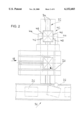
- FIG. 1 is a lateral view of an apparatus in accordance with the invention
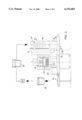
- FIG. 2 is a top view of the apparatus of FIG. 1,
- FIG. 3 is a front view of the apparatus of FIGS. 1 and 2,
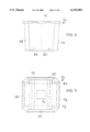
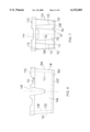
- FIG. 4 is a lateral view of a first embodiment of a container of the invention
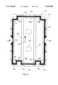
- FIG. 5 is a top view of the container of FIG. 4,
- FIG. 6 is a lateral view of a second embodiment of a container of the invention.
- FIG. 7 is a further lateral view of the container of FIG. 6,
- FIG. 8 is a top view of the container of FIGS. 6 and 7,
- FIG. 9 is a perspective view of a number of containers of FIGS. 6 to 8 stacked inside each other.
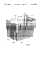
- FIG. 10 is a perspective view of a number of containers of FIGS. 6 to 9 stacked on top of each other.
- FIGS. 1 to 3 An apparatus which can be used for executing a method in accordance with the invention for ready-for-shipment packaging of printed matter in containers suitable therefor is shown in FIGS. 1 to 3.
- printed matter 14 transported by clamping devices 12 disposed on a transport device 10 to a conveyor belt 16 are dropped on the conveyor belt 16 and are transported by it to a folding machine 18.
- the conveyor belt 16 and the folding machine 18 form a conveying device terminating in a supply chute 20 of a device for loading printed matter into a container 26 placed thereunder.
- the printed matter 14 dropped into the supply chute 20 at the end of the folding machine 18 forms a stack 25 of printed matter on the comb-like tines 24 of a stacking device 22 disposed in the interior of the supply chute, which can be introduced crosswise to the direction of the force of gravity into the lower area of the supply chute 20.
- the comb-like tines 24 of the stacking device 22 can be removed from the interior of the supply chute 20, so that the stack 25 of printed matter previously placed on them can fall into a container 26 disposed underneath the supply chute 20.
- the folding edges of the printed matter in the stack 25 of printed matter lie on top of each other.
- a support disk 28 embodied as a rotating lifting platform is disposed below the supply chute 20.
- the support disk 28 can be brought into contact with the bottom of the container 26 by means of a lift piston device 30 or can possibly be introduced into a receptacle provided on the bottom of the container 26 for the coupling, fixed against relative rotation, of the container with the support disk in order to subsequently release the former from a transport device 32 used for transporting the container 26 underneath the supply chute 20.
- the transport device 32 has two horizontal conveyor belts 34 extending parallel with each other at a distance, between which the support disk 28 can be brought to rest against the container bottom or can possibly be introduced into a receptacle disposed on the bottom of the shipping container 26.
- the lift piston device 30 for introducing the support disk 28 into the receptacle provided on the bottom of the container 26, it is also provided to lower the conveyor belts 34 in the area below the supply chute 20 by means of a lowering device in order to free the container 26 from the conveyor belts 34 and to make possible the turning of the container 26 which then rests on the support disk 28.
- the containers 26 can be transferred by means of the transport device 32 to a further conveyor belt 36, which then transports the loaded containers to a loading station.
- catches 38 are fixed on its conveyor belts 34 and form a stop for the containers 26 to be transported on them.
- the apparatus of the invention has a vertically disposed magazine 40 for receiving the containers 26 stacked inside each other.
- the magazine 40 is bordered by a guide wall 42 and two oppositely disposed vertical conveyors 44.
- Gripping finger 46 are fixed on the vertical conveyors 44, as can be seen in FIG. 2, on which rest the lower edges of handling strips 48 which encircle the upper edges of the containers 26 received in the magazine and stacked inside each other.
- the gripping fingers with the vertical conveyors 44 are moved downward.
- the gripping fingers 46 forming the support for the handling strip 48 of the lowest container in the magazine 40 release this lowest container, so that it falls on the conveyor belts 36 by the action of the force of gravity. In this way it is possible to realize a particularly simple separation of the containers 26 stacked inside each other in the magazine.
- the distance of the lower end of the vertical conveyor from the conveyor belts 36 in this case approximately corresponds to twice the height of the container 26.
- the device for transporting the containers 26 extends approximately vertically to the direction in which the printed matter 14 is brought to the supply chute 20. If it is necessary for spatial reasons, however, an arrangement can also be used wherein the two transport devices extend parallel to each other.
- the printed matter is dropped by the transport device 10 in a regular formation, namely as a stream of pieces placed on top of each other in a fish-scale pattern, on the conveyor belt 16, which forms a part of the device for conveying printed matter to the supply chute 20.
- the transport device can be used, for example, for transporting printed matter 14 from the end of an inserting machine or a collecting folder to the conveyor belt 16.
- the functions of the transport device 10, the conveyor belt 16, the folding machine 20, the stacking device 22, the lift piston device 30, the transport device 32 and the vertical conveyors 44 are customarily adjusted to each other by computer control.
- the printed matter 14 is transported in a container 26 to a distribution point 80, where the printed matter is removed prior to returning the container to the packaging device, as shown in FIG. 3.
- the apparatus as a whole can be embodied as a mobile unit.
- a container of the invention comprises a bottom 60 and, extending therefrom, lateral pieces 62, 64, 66 and 68, which respectively enclose an obtuse angle with the bottom 60.
- the lateral pieces 62 and 66 extend from lateral edges of a deposit surface 70, which is adapted to the format of the printed matter to be placed into the container and indicated by dashed lines.
- the lateral pieces 62 and 66 extend over the entire length of the shortest edges of the deposit surface 70 and at their respective ends also cover the end areas of the longer lateral edges of the deposit surface 70.
- the inner surfaces of the lateral pieces 62 and 66 form resting surfaces along all lateral edges of the deposit surface 70 for printed matter to be placed on the deposit surface 70. In this way it is possible to prevent an essentially lateral shifting of the deposited printed matter in the container.
- a free space between the resting surfaces for the printed matter to be deposited into the container is respectively formed between the ends of the lateral pieces 62 and 66 extending from the end areas of the longer lateral edges of the deposit surface 70.
- the lateral edges of the printed matter to be deposited on the deposit surface 70 are free in the area of these free spaces, because of which a possibility of grasping the printed matter to be introduced into the container and for their easier removal from the container is created.
- further lateral pieces 64 and 68 start outside of the deposit surface 70 and extend to the upper container edge.
- a free space, open at the top, which assures a simple removal of the printed matter, is bordered by the further lateral pieces 64 and 68 and by the printed matter placed on the deposit surface 70.
- the further lateral pieces 64 and 68 directly adjoining the lateral pieces 62 and 66 provide protection for the printed matter on the deposit surface 70 not enclosed by the lateral pieces 62 and 66.
- a particularly good protection is achieved in that the lateral pieces constitute continuous lateral walls completely enclosing the container interior.
- the further lateral pieces 64 and 68 extend from lateral edges of a second deposit surface 72 on the bottom 60, which corresponds to a second piece of printed matter indicated by dash-dotted lines.
- the embodiment of the further lateral pieces 64 and 68 in respect to the second deposit surface 72 completely corresponds to that of the lateral pieces 62 and 66 in respect to the first deposit surface 70.
- an essential lateral shifting of printed matter placed on the deposit surface 72 is prevented by the lateral pieces 64 and 68 in a manner similar to that of the lateral pieces 62 and 66.
- the deposit free from jamming and bending of printed matter on the second deposit surface 72 is assured and access to the printed matter placed thereupon is made easier.
- the lateral pieces 62 and 66 delimit a free space, open to the top, for printed matter placed on the deposit surface 72.
- the deposit surfaces 70 and 72 correspond to the same printed matter formats.
- the use of deposit surfaces corresponding to the format of several pieces of printed matter placed next to each other has been considered.
- the embodiment of the lateral pieces 62 and 68 enclosing an obtuse angle with the bottom 60 also allows the stacking of several containers of the same shape inside each other. More exactly stated, this embodiment makes it possible that an area of the lateral wall of the container 26 extending from the bottom 60 to the container edge adjoining the bottom 60 and formed by the lateral pieces 62 to 68 can be received in the upper area of the container interior of a container of the same type, by means of which the capability of stacking them inside each other is assured in the end.
- the outer contour of the container essentially corresponds to its inner contour in the exemplary embodiment illustrated, so that in general the exterior wall of a container to be stacked in a container of the same type disposed under it comes to rest completely against the interior wall of the container underneath.
- a through-opening 74 is formed in the container bottom 60, which is simultaneously used for coupling, in a manner fixed against relative rotation, with the turntable 28 when introduced in an apparatus of the invention for the ready-for-shipment packaging of printed matter.
- a handling strip 76 which projects toward the outside and extends around the upper container edge, is attached on the upper container edge and is intended to ease the transport of individual containers.
- the underside of the handling strip 74 forms a support for the gripping fingers 46 attached to the vertical conveyor 44 used as the separating device in the apparatus of the invention (see FIG. 3).
- Support surfaces are furthermore formed by the handling strip 76, on which containers stacked inside each other can be supported.
- FIGS. 6 to 10 An embodiment of a container in accordance with the invention, which can be stacked inside and on top of each other will be described below by means of FIGS. 6 to 10.
- lateral pieces 104 to 114 enclosing an obtuse angle with the container bottom 100, extend from the lateral edges of a deposit surface 102 on the container bottom 100, which is adapted to the format of a piece of printed matter and is indicated in the drawing by dashed lines, to the upper edge of the container (see FIGS. 6 and 7).
- the interior surfaces of the lateral pieces 104 to 114 form resting surfaces for the printed matter to be placed on the deposit surface 102 and which prevent an essentially lateral shifting of these pieces of printed matter in the container.
- the angle between the lateral pieces 104 to 114 and the container bottom 100 is less than 100°, particularly preferred are approximately 95°. Free spaces are formed between the lateral pieces 114 and 104 or 108 and 110, which ease access to the printed matter to be placed on the deposit surface 102.
- the lateral pieces 104 and 114 extending from one of the shorter edges of the rectangular deposit surface 102 are disposed on the respective ends of this shorter edge, while the lateral pieces 108 and 110 associated with the other shorter lateral edge of the deposit surface 102 extend from the bottom 100, keeping a distance from the ends of this lateral edge.
- the end of the lateral piece 114 (104) facing away from the lateral piece 112 (106) is offset in the direction toward the center of the shorter edge of the deposit surface 102 in relation to the end of the lateral piece 110 (108) facing the lateral piece 112 (106).
- the further lateral pieces 118 to 136 extending from areas of the bottom 100 located outside the deposit surface 102 connect the lateral pieces 104 to 114 forming the resting surfaces for the printed matter to be placed on the deposit surface 102 in such a way that a lateral container wall is formed which is continuous in the circumferential direction.
- a first free space, open at the top is formed by the lateral pieces 134, 136 and 118, together with the corresponding lateral edges of the printed matter to be placed on the deposit surface 102
- a second free space, open at the top, located opposite the first free space is formed by the lateral pieces 124, 126 and 128, together with the corresponding lateral edges of the printed matter to be placed on the deposit surface 102.
- the second free space has a lesser width along the corresponding lateral edge of the deposit surface 102 than the first free space.
- the further lateral pieces 118 to 136 also enclose an obtuse angle of preferably less than 100°, particularly preferred of approximately 95°, with the bottom 100. It is assured by this that several containers of the same type can be stacked inside each other if they have the same orientation, as indicated by the arrows 140 in FIG. 9. On the other hand, the particular arrangement of the lateral pieces 104 to 136 makes it possible to stack several containers of the same type, but with alternating orientation 140 (see FIG.
- the lower edges of the lateral pieces 134, 136 and 118 come to rest against the upper edges of the lateral pieces 110, 128 and 108 of a container disposed below it, having an orientation turned by 180° in relation to the upper container. Furthermore, the lower edges of the lateral pieces 122 and 130 of the container on the top come to rest on the upper edges of the lateral pieces 114 or 104 of the container on the bottom. Thus, in the stacked position the edges of one of the lateral pieces forming a resting surface respectively rest against the edges of a further lateral piece.
- a handling strip 142 which projects outward and, in respect to the upper edges of the lateral pieces, also upward and essentially extends all around is provided on the upper container edge.
- a receptacle for the bottom of a container of the same kind to be stacked on it is realized by means of this arrangement of the handling strip in respect to the upper container edge, by means of which during stacking of the described containers a displacement of the upper container in respect to the container disposed under it can be prevented (see FIG. 10).
- recesses 144 forming transport handles are provided in the lateral pieces 126 and 136 in the embodiment shown in FIGS. 6 to 10. Furthermore, two through-openings 146 have been cut in the bottom of this container, which serve the same purpose as the through-opening 74 of the container of the invention in accordance with FIGS. 4 and 5.
- the described container shape allows transport of printed matter in containers stacked on top of each other, wherein damage of the piece of printed matter respectively placed on top in one of the containers is prevented by the bottom of the container stacked on top of it, as well as the space-saving return of the containers to the packaging apparatus in stacked form after removal of the printed matter.
- a guide device formed by two guide grooves 150 extending parallel to each other is provided on the container bottom 100, as can be seen particularly clearly in FIG. 7.
- these guide grooves can be used for receiving guide rails (not shown) disposed between the conveyor belts, in order to assure in this way the orientation below the supply chute 20 required for loading.
- the walls of the guide grooves 150 project into the container interior for forming a resting strip therein in order to assure in this way a particularly rapid removal by means of a lateral venting of an air cushion created by the pieces of printed material falling into the container.
- the containers described by means of FIGS. 4 to 10 are essentially cube-shaped, because of which a space-saving transport of containers stacked inside and/or on top of each other is made possible.
- different container shapes are conceivable for shipping printed matter of other formats, for example essentially circular-cylindrical container shapes.
- the containers are preferably made of plastic.
- a different material for example metal
Landscapes
- Engineering & Computer Science (AREA)
- Mechanical Engineering (AREA)
- Stacking Of Articles And Auxiliary Devices (AREA)
- Stackable Containers (AREA)
Applications Claiming Priority (2)
| Application Number | Priority Date | Filing Date | Title |
|---|---|---|---|
| CH323293 | 1993-10-27 | ||
| CH03232/93 | 1993-10-27 |
Publications (1)
| Publication Number | Publication Date |
|---|---|
| US6152683A true US6152683A (en) | 2000-11-28 |
Family
ID=4251513
Family Applications (1)
| Application Number | Title | Priority Date | Filing Date |
|---|---|---|---|
| US08/330,127 Expired - Fee Related US6152683A (en) | 1993-10-27 | 1994-10-27 | Method, apparatus and container for shipping printed matter |
Country Status (4)
| Country | Link |
|---|---|
| US (1) | US6152683A (fr) |
| EP (1) | EP0654435B1 (fr) |
| JP (1) | JPH07206160A (fr) |
| DE (1) | DE59408112D1 (fr) |
Cited By (5)
| Publication number | Priority date | Publication date | Assignee | Title |
|---|---|---|---|---|
| US6488154B1 (en) * | 2000-10-16 | 2002-12-03 | Ming-Chuan Yeh | Chip tray |
| US20030138312A1 (en) * | 2002-01-22 | 2003-07-24 | Watson Michael B. | Depalletizer for a material handling system |
| US20040098948A1 (en) * | 2002-11-19 | 2004-05-27 | Caporali Michael E. | Vertical flat stacking apparatus and method of use |
| US6769862B1 (en) * | 2002-12-03 | 2004-08-03 | Jeffrey B. Kuhl | Apparatus and method for placing horizontally oriented flats into vertically extending stacks thereof |
| US11427361B2 (en) * | 2017-07-03 | 2022-08-30 | Giesecke+Devrient Currency Technology Gmbh | Device and method for filling containers with value documents, in particular banknotes, and system for processing value documents |
Families Citing this family (1)
| Publication number | Priority date | Publication date | Assignee | Title |
|---|---|---|---|---|
| GB9915467D0 (en) * | 1999-07-02 | 1999-09-01 | Rotapak Ltd | Container handling |
Citations (30)
| Publication number | Priority date | Publication date | Assignee | Title |
|---|---|---|---|---|
| US1690920A (en) * | 1925-07-02 | 1928-11-06 | Bergmann Packaging Machine Com | Cup-depositing mechanism for unit-measuring machines |
| CH367750A (fr) * | 1960-03-04 | 1963-02-28 | Rose Brothers Ltd | Appareil pour transférer un à un des récipients emboîtés constituant une pile |
| FR1363792A (fr) * | 1963-07-19 | 1964-06-12 | Diamond National Corp | Machine à distribuer et à désemboîter |
| US3283955A (en) * | 1964-01-29 | 1966-11-08 | Keyes Fibre Co | Dispensing apparatus for nested articles |
| US3403814A (en) * | 1967-09-26 | 1968-10-01 | Shell Oil Co | Stacking container with tapered ledge and rib for stacking interlock |
| US3491681A (en) * | 1968-03-07 | 1970-01-27 | Joseph Z Saro Jr | Baling and storage container |
| US3658194A (en) * | 1970-05-11 | 1972-04-25 | Baker Perkins Inc | Gravity type pan unstacker |
| GB1281757A (en) * | 1969-08-11 | 1972-07-12 | Yuji Fujishiro | Bundling printed sheets |
| US3734341A (en) * | 1971-07-12 | 1973-05-22 | North American Rockwell | Nestable and stackable container |
| US3773213A (en) * | 1971-07-23 | 1973-11-20 | Gilbert N | Shipping and dispensing container |
| US4027796A (en) * | 1975-12-01 | 1977-06-07 | Consumers Glass Company Limited | Stackable and nestable container |
| DE2715705A1 (de) * | 1976-04-23 | 1977-11-03 | Grapha Holding Ag | Paketausleger |
| DE2756473A1 (de) * | 1977-12-17 | 1979-06-21 | Will E C H Gmbh & Co | Vorrichtung zum einfuellen von papierstapeln in schachteln |
| US4214743A (en) * | 1977-10-24 | 1980-07-29 | Ferag Ag | Apparatus for dividing a continuous stream of flat products, especially printed products, into individual sections |
| US4293272A (en) * | 1978-11-20 | 1981-10-06 | Staalkat B.V. | Method and apparatus for denesting a plurality of containers filled with articles |
| GB2082548A (en) * | 1980-08-15 | 1982-03-10 | Ferag Ag | Apparatus for forming stacks from continuously arriving substantially flat products |
| DE3104279A1 (de) * | 1981-02-07 | 1982-09-16 | Franz Delbrouck Gmbh, 5750 Menden | Steige, insbesondere fuer obst oder gemuese |
| EP0067399A1 (fr) * | 1981-06-12 | 1982-12-22 | Albert-Frankenthal AG | Dispositif pour ajuster des produits |
| GB2116514A (en) * | 1982-03-09 | 1983-09-28 | Will E C H | Apparatus for introducing stacks of paper sheets or the like into cartons |
| EP0095576A2 (fr) * | 1982-05-27 | 1983-12-07 | Rockwell International Corporation | Appareil de chargement d'un conteneur pour journaux |
| EP0263735A1 (fr) * | 1986-09-26 | 1988-04-13 | Garnier Ponsonnet-Vuillard S.A. | Dispositif de conditionnement automatique de produits plats tels que des enveloppes |
| DE3637610A1 (de) * | 1986-11-05 | 1988-05-11 | Stiegler Maschf Gmbh | Vorrichtung zum verpacken von beutelstapeln |
| DD265601A1 (de) * | 1987-11-02 | 1989-03-08 | Konsum Rationalisierungszentru | Bechervereinzelungseinrichtung |
| US4829742A (en) * | 1987-03-09 | 1989-05-16 | Centind - Centro Studi Industriali - S.R.L. | Automatic machine for the continuous production of dual-use filter sachets for infusion products |
| US4915578A (en) * | 1988-07-25 | 1990-04-10 | Total Tote, Inc. | Bin unstacking machine |
| EP0365870A2 (fr) * | 1988-10-24 | 1990-05-02 | Am International Incorporated | Dispositif de manipulation de cahiers |
| US5046617A (en) * | 1988-08-17 | 1991-09-10 | Focke & Co. (Gmbh & Co.) | Apparatus for the feeding of blanks to a packaging machine |
| US5069598A (en) * | 1988-10-24 | 1991-12-03 | Am International Incorporated | Apparatus and method for loading sheet material articles |
| US5176494A (en) * | 1989-12-14 | 1993-01-05 | Nigrelli Systems, Inc. | Stacked article destacking and feeding system |
| US5344021A (en) * | 1993-09-21 | 1994-09-06 | Formall, Inc. | Molded crate with interlocking rim appliances |
-
1994
- 1994-10-19 DE DE59408112T patent/DE59408112D1/de not_active Expired - Fee Related
- 1994-10-19 EP EP94810608A patent/EP0654435B1/fr not_active Expired - Lifetime
- 1994-10-24 JP JP6258463A patent/JPH07206160A/ja active Pending
- 1994-10-27 US US08/330,127 patent/US6152683A/en not_active Expired - Fee Related
Patent Citations (30)
| Publication number | Priority date | Publication date | Assignee | Title |
|---|---|---|---|---|
| US1690920A (en) * | 1925-07-02 | 1928-11-06 | Bergmann Packaging Machine Com | Cup-depositing mechanism for unit-measuring machines |
| CH367750A (fr) * | 1960-03-04 | 1963-02-28 | Rose Brothers Ltd | Appareil pour transférer un à un des récipients emboîtés constituant une pile |
| FR1363792A (fr) * | 1963-07-19 | 1964-06-12 | Diamond National Corp | Machine à distribuer et à désemboîter |
| US3283955A (en) * | 1964-01-29 | 1966-11-08 | Keyes Fibre Co | Dispensing apparatus for nested articles |
| US3403814A (en) * | 1967-09-26 | 1968-10-01 | Shell Oil Co | Stacking container with tapered ledge and rib for stacking interlock |
| US3491681A (en) * | 1968-03-07 | 1970-01-27 | Joseph Z Saro Jr | Baling and storage container |
| GB1281757A (en) * | 1969-08-11 | 1972-07-12 | Yuji Fujishiro | Bundling printed sheets |
| US3658194A (en) * | 1970-05-11 | 1972-04-25 | Baker Perkins Inc | Gravity type pan unstacker |
| US3734341A (en) * | 1971-07-12 | 1973-05-22 | North American Rockwell | Nestable and stackable container |
| US3773213A (en) * | 1971-07-23 | 1973-11-20 | Gilbert N | Shipping and dispensing container |
| US4027796A (en) * | 1975-12-01 | 1977-06-07 | Consumers Glass Company Limited | Stackable and nestable container |
| DE2715705A1 (de) * | 1976-04-23 | 1977-11-03 | Grapha Holding Ag | Paketausleger |
| US4214743A (en) * | 1977-10-24 | 1980-07-29 | Ferag Ag | Apparatus for dividing a continuous stream of flat products, especially printed products, into individual sections |
| DE2756473A1 (de) * | 1977-12-17 | 1979-06-21 | Will E C H Gmbh & Co | Vorrichtung zum einfuellen von papierstapeln in schachteln |
| US4293272A (en) * | 1978-11-20 | 1981-10-06 | Staalkat B.V. | Method and apparatus for denesting a plurality of containers filled with articles |
| GB2082548A (en) * | 1980-08-15 | 1982-03-10 | Ferag Ag | Apparatus for forming stacks from continuously arriving substantially flat products |
| DE3104279A1 (de) * | 1981-02-07 | 1982-09-16 | Franz Delbrouck Gmbh, 5750 Menden | Steige, insbesondere fuer obst oder gemuese |
| EP0067399A1 (fr) * | 1981-06-12 | 1982-12-22 | Albert-Frankenthal AG | Dispositif pour ajuster des produits |
| GB2116514A (en) * | 1982-03-09 | 1983-09-28 | Will E C H | Apparatus for introducing stacks of paper sheets or the like into cartons |
| EP0095576A2 (fr) * | 1982-05-27 | 1983-12-07 | Rockwell International Corporation | Appareil de chargement d'un conteneur pour journaux |
| EP0263735A1 (fr) * | 1986-09-26 | 1988-04-13 | Garnier Ponsonnet-Vuillard S.A. | Dispositif de conditionnement automatique de produits plats tels que des enveloppes |
| DE3637610A1 (de) * | 1986-11-05 | 1988-05-11 | Stiegler Maschf Gmbh | Vorrichtung zum verpacken von beutelstapeln |
| US4829742A (en) * | 1987-03-09 | 1989-05-16 | Centind - Centro Studi Industriali - S.R.L. | Automatic machine for the continuous production of dual-use filter sachets for infusion products |
| DD265601A1 (de) * | 1987-11-02 | 1989-03-08 | Konsum Rationalisierungszentru | Bechervereinzelungseinrichtung |
| US4915578A (en) * | 1988-07-25 | 1990-04-10 | Total Tote, Inc. | Bin unstacking machine |
| US5046617A (en) * | 1988-08-17 | 1991-09-10 | Focke & Co. (Gmbh & Co.) | Apparatus for the feeding of blanks to a packaging machine |
| EP0365870A2 (fr) * | 1988-10-24 | 1990-05-02 | Am International Incorporated | Dispositif de manipulation de cahiers |
| US5069598A (en) * | 1988-10-24 | 1991-12-03 | Am International Incorporated | Apparatus and method for loading sheet material articles |
| US5176494A (en) * | 1989-12-14 | 1993-01-05 | Nigrelli Systems, Inc. | Stacked article destacking and feeding system |
| US5344021A (en) * | 1993-09-21 | 1994-09-06 | Formall, Inc. | Molded crate with interlocking rim appliances |
Cited By (8)
| Publication number | Priority date | Publication date | Assignee | Title |
|---|---|---|---|---|
| US6488154B1 (en) * | 2000-10-16 | 2002-12-03 | Ming-Chuan Yeh | Chip tray |
| US20030138312A1 (en) * | 2002-01-22 | 2003-07-24 | Watson Michael B. | Depalletizer for a material handling system |
| US7033130B2 (en) * | 2002-01-22 | 2006-04-25 | Rapistan Systems Advertising Corp. | Depalletizer for a material handling system |
| US20040098948A1 (en) * | 2002-11-19 | 2004-05-27 | Caporali Michael E. | Vertical flat stacking apparatus and method of use |
| US7137234B2 (en) | 2002-11-19 | 2006-11-21 | Lockheed Martin Corporation | Vertical flat stacking apparatus and method of use |
| US20060272292A1 (en) * | 2002-11-19 | 2006-12-07 | Lockheed Martin Corporation | Vertical flat stacking apparatus and method of use |
| US6769862B1 (en) * | 2002-12-03 | 2004-08-03 | Jeffrey B. Kuhl | Apparatus and method for placing horizontally oriented flats into vertically extending stacks thereof |
| US11427361B2 (en) * | 2017-07-03 | 2022-08-30 | Giesecke+Devrient Currency Technology Gmbh | Device and method for filling containers with value documents, in particular banknotes, and system for processing value documents |
Also Published As
| Publication number | Publication date |
|---|---|
| EP0654435A3 (fr) | 1995-08-09 |
| EP0654435A2 (fr) | 1995-05-24 |
| JPH07206160A (ja) | 1995-08-08 |
| EP0654435B1 (fr) | 1999-04-14 |
| DE59408112D1 (de) | 1999-05-20 |
Similar Documents
| Publication | Publication Date | Title |
|---|---|---|
| EP1799554B1 (fr) | Dispositif pour remplir des cartons | |
| US5794416A (en) | Computer controlled system for loading pallets in a confined cargo area | |
| FI3858768T3 (fi) | Menetelmä pinottavien kappaletavarapakkausten purkamiseksi lavalta | |
| JP2982643B2 (ja) | 袋自動解荷供給方法並びにその装置、及び該装置で使用される袋輸送コンテナ、解束装置、トレー | |
| EP0361128B1 (fr) | Dispositif pour le déballage et l'alimentation de flans pour des emballages | |
| EP1607332A1 (fr) | Barquette de stockage de sachets vides, conteneur de transport de barquettes, procédé et dispositif de transport et d'approvisionnement de groupes de sachets | |
| US6152683A (en) | Method, apparatus and container for shipping printed matter | |
| JP3088942B2 (ja) | 製品パッケージ箱詰め装置 | |
| JPH05330528A (ja) | ケースの自動開箱・物品取り出し・折畳装置 | |
| WO2000071448A1 (fr) | Procede de transfert d'objets individuels jusqu'a une unite remplie de palettes | |
| CN1329250C (zh) | 形成负载单元的系统和方法 | |
| JPH07291451A (ja) | 箱物の段積み方法及びその装置 | |
| US6679030B2 (en) | Installation for treating bottles | |
| EP0365870B1 (fr) | Dispositif de manipulation de cahiers | |
| US6189294B1 (en) | Packaging for highly perishable, flexible slices of food, and process for inserting the slices | |
| JPH07101550A (ja) | 物品処理装置 | |
| JP3732949B2 (ja) | 書籍等の取出装置 | |
| JP3232978B2 (ja) | 個装単位切出し装置 | |
| JPH0326143Y2 (fr) | ||
| JPH01247328A (ja) | 円柱状包装体の移送装置と移送方法 | |
| ES2170736T3 (es) | Dispositivo para formar y alinear paquetes de productos de imprenta apilados en forma suelta. | |
| JP3942229B2 (ja) | 物品の集積体 | |
| JPH0457707A (ja) | 物品の集積箱詰装置における内外フラップ開放閉鎖方法および開放閉鎖機構 | |
| JPH08169543A (ja) | 箱の段積格納装置 | |
| JP2002249202A (ja) | 搬送保管装置 |
Legal Events
| Date | Code | Title | Description |
|---|---|---|---|
| AS | Assignment |
Owner name: GRAPHA-HOLDING AG, SWITZERLAND Free format text: ASSIGNMENT OF ASSIGNORS INTEREST;ASSIGNOR:LINDER, HEINZ;REEL/FRAME:007315/0815 Effective date: 19941116 |
|
| FEPP | Fee payment procedure |
Free format text: PAYOR NUMBER ASSIGNED (ORIGINAL EVENT CODE: ASPN); ENTITY STATUS OF PATENT OWNER: LARGE ENTITY |
|
| FPAY | Fee payment |
Year of fee payment: 4 |
|
| REMI | Maintenance fee reminder mailed | ||
| LAPS | Lapse for failure to pay maintenance fees | ||
| STCH | Information on status: patent discontinuation |
Free format text: PATENT EXPIRED DUE TO NONPAYMENT OF MAINTENANCE FEES UNDER 37 CFR 1.362 |
|
| FP | Lapsed due to failure to pay maintenance fee |
Effective date: 20081128 |