US7963050B2 - Sports boot with articulated upper cuff to provide a position for walking - Google Patents
Sports boot with articulated upper cuff to provide a position for walking Download PDFInfo
- Publication number
- US7963050B2 US7963050B2 US11/973,789 US97378907A US7963050B2 US 7963050 B2 US7963050 B2 US 7963050B2 US 97378907 A US97378907 A US 97378907A US 7963050 B2 US7963050 B2 US 7963050B2
- Authority
- US
- United States
- Prior art keywords
- fastening
- rocker
- cable
- unfastening
- boot
- Prior art date
- Legal status (The legal status is an assumption and is not a legal conclusion. Google has not performed a legal analysis and makes no representation as to the accuracy of the status listed.)
- Expired - Fee Related, expires
Links
Images




Classifications
-
- A—HUMAN NECESSITIES
- A43—FOOTWEAR
- A43B—CHARACTERISTIC FEATURES OF FOOTWEAR; PARTS OF FOOTWEAR
- A43B5/00—Footwear for sporting purposes
- A43B5/04—Ski or like boots
- A43B5/0427—Ski or like boots characterised by type or construction details
- A43B5/047—Ski or like boots characterised by type or construction details provided with means to improve walking with the skiboot
- A43B5/0474—Ski or like boots characterised by type or construction details provided with means to improve walking with the skiboot having a walk/ski position
-
- A—HUMAN NECESSITIES
- A43—FOOTWEAR
- A43C—FASTENINGS OR ATTACHMENTS OF FOOTWEAR; LACES IN GENERAL
- A43C11/00—Other fastenings specially adapted for shoes
- A43C11/16—Fastenings secured by wire, bolts, or the like
Definitions
- the invention relates to a sports boot in the form of a rigid upper made up of an upper cuff articulated to a shell surrounding the foot and equipped with a device for fastening the upper cuff to the shell in order to fasten the upper cuff in an inclined position relative to the shell in a first position for practicing the sport, and to unfasten the upper cuff from the shell in a second position for not practicing the sport, for example to make the boot easier to put on and to walk in.
- the invention is specifically concerned with the device for fastening the upper cuff to the shell, the operation of which is linked to a remote fastening and unfastening member, such as a lever connected to the means used to fasten and tighten the sports boot, for example.
- the device for fastening the upper cuff to the shell relies on a rocker positioned on the upper cuff and collaborating with a stop piece belonging to the shell, the operation of which is controlled by a buckle used to open the boot via a connecting cable.
- a buckle used to open the boot via a connecting cable.
- a second solution reuses the essential features of the mechanism, that is to say a rocker connected by a cable to a buckle of the boot.
- the rocker is actuated by pulling the cable, this being brought about by opening the boot buckle.
- This principle guarantees better unfastening of the upper cuff.
- this solution has the disadvantage of being highly complex because it relies on a first spring to compensate for the differences between the long travel of the cable and the small-amplitude of the movement of the rocker, and then on a second spring to actuate the rocker.
- a general subject of the present invention is a sports boot with a device for fastening/unfastening the upper cuff with respect to the shell but not having the disadvantages of the prior art.
- a first subject of the present invention is a sports boot with a fastening/unfastening device that performs well, particularly in the phase of unfastening the upper cuff.
- the second subject of the present invention is a sports boot with a fastening/unfastening device the mechanism of which is simple, not very bulky, and inexpensive.
- the invention relies on a solution involving tension in the cable in order to unfasten the upper cuff, in combination with an element for controlling this unfastening that uses a cam surface.
- FIG. 1 is a side view in section on a vertical plane of part of a boot with a fastening mechanism according to a first embodiment of the invention, in a fastened position;
- FIG. 2 is a side view of a ski boot incorporating a fastening mechanism according to the first embodiment of the invention, in a fastened position;
- FIG. 3 is a perspective view of the fastening mechanism according to the first embodiment of the invention.
- FIG. 4 is a side view in section on a vertical plane of part of a boot with a fastening mechanism according to the first embodiment of the invention, in an unfastened position;
- FIG. 5 is a side view in section on a vertical plane of part of a boot with a fastening mechanism according to the first embodiment of the invention, in an unfastened position with the upper cuff standing up straight;
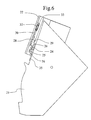
- FIG. 6 is a side view in section on a vertical plane of part of a boot with a fastening mechanism according to a second embodiment of the invention, in a fastened position;
- FIG. 7 is a cross section through a perspective view of the fastening mechanism according to the second embodiment of the invention.
- FIG. 8 is a perspective view of the fastening mechanism according to the second embodiment of the invention.
- FIG. 9 is a side view in section on a vertical plane of part of a boot with a fastening mechanism according to the second embodiment of the invention, in an unfastened position;
- FIG. 10 is a side view in section on a vertical plane of part of a boot with a fastening mechanism according to the second embodiment of the invention in an unfastened position with the upper cuff standing up;
- FIG. 11 is a side view in section on a vertical plane of part of a boot with a fastening mechanism according to a third embodiment of the invention, in a fastened position;
- FIG. 12 is an exploded perspective view of the fastening mechanism according to the third embodiment of the invention.
- FIG. 13 is another exploded perspective view of the fastening mechanism according to the third embodiment of the invention.
- FIG. 14 is a side view in section on a vertical plane of part of a boot with a fastening mechanism according to the third embodiment of the invention, in an unfastened position;
- FIG. 15 is a side view in section on a vertical plane of part of a boot with a fastening mechanism according to the third embodiment of the invention in an unfastened position with the upper cuff standing up straight;
- FIG. 16 is a side view in section on a vertical plane of part of a boot with a fastening mechanism according to a fourth embodiment of the invention, in a fastened position;
- FIG. 17 is an exploded perspective view of the fastening mechanism according to the fourth embodiment of the invention.
- FIG. 18 is a side view in section on a vertical plane of part of a boot with a fastening mechanism according to the fourth embodiment of the invention in an unfastening phase;
- FIG. 19 is a side view in section on a vertical plane of part of a boot with a fastening mechanism according to the fourth embodiment of the invention in an unfastened position;
- FIG. 20 is a side view in section on a vertical plane of part of a boot with a fastening mechanism according to the fourth embodiment of the invention in an unfastened position with the upper cuff stood up straight;
- FIG. 21 is a side view in section on a vertical plane of part of a boot with a fastening mechanism according to an alternative form of the fourth embodiment of the invention, in a fastened position.
- the invention will be described in its application to a ski boot. However, it could be applied to any kind of sports boot or shoe with a rigid upper, that is to say an upper comprising an upper cuff and a shell substantially made of a material at least as rigid as a polyurethane with a hardness of 40 Shore D.
- the upper cuff 2 is connected to the shell 1 by a rear fastening/unfastening device positioned in a housing 3 provided between the two elements.
- the fastening/unfastening device relies on a rocker 4 mounted such that it can move in terms of rotation about a pivot 5 secured to the upper cuff and which has a lower free end 6 that can collaborate with a stop piece 7 belonging to the shell 1 .
- the device further comprises a rotary component 8 of the drum type, mounted such that it can move on the upper cuff, in the form of a disk of which the opposite surface to the one facing the interior surface 14 of the upper cuff has an irregular relief so as to form a cam surface 9 which collaborates with the rocker 4 .
- This drum 8 comprises a hollowed annular part 11 to accept a cable 10 over its circumference.
- the cable 10 has a first end connected to a fastening and unfastening member, which corresponds to the upper fastening and tightening buckle 80 of the upper cuff 2 , and a second end connected to the drum 8 subjected to a return spring 12 fixed to the upper cuff 2 at a point 13 .
- This return spring 12 acts on the drum 8 via a direct connection with the end of the cable 10 .
- a spiral-shaped spring positioned within the drum could perform an equivalent return function.
- This device is secured to the interior surface 14 of the upper cuff 2 by at least one support and reinforcing plate 15 comprising arms 16 between which the substantially horizontal pivot 5 is mounted parallel to the wall 14 of the rocker 4 .
- This plate 15 additionally comprises a housing for the pivot perpendicular to the wall 14 of the drum 8 .
- a spring 17 positioned at the pivot 5 acts on the rocker 4 to cause it to tend to rotate in the direction that moves it away from the shell 1 and therefore towards the position in which the upper cuff 2 is unfastened.
- FIG. 1 illustrates the fastened position of the upper cuff 2 , which occupies an inclined position optimal for skiing relative to the shell 1 .
- the cable 10 is released but kept taut, its end occupying a raised position in the space 3 under the effect of the spring 12 .
- This position of the cable 10 corresponds to a position of the drum 8 in which the thickest portion 18 of its cam surface 9 bears against the rocker 4 so as to keep the end 6 thereof pressed against the stop piece 7 belonging to the shell.
- the upper cuff 2 cannot straighten up and therefore does remain in the fastened inclined position needed for skiing.
- FIGS. 4 and 5 illustrate the unfastened configuration of the upper cuff 2 .
- the skier By opening the fastening buckle 80 to which the cable 10 is fixed, the skier introduces tension into the cable and this causes the drum 8 to rotate through half a revolution allowing the thickest part 18 of the cam surface 9 to be directed downwards, while the thinner surface 19 finds itself positioned towards the top, thus releasing the rocker 4 which moves away from the shell 1 under the effect of the return spring 17 while at the same time remaining in contact with the cam surface 9 of the drum 8 .
- the geometry of the cam surface 9 of the drum 8 is such that it allows the end 6 of the rocker 4 to escape the actions of the stop piece 7 of the shell 1 in this configuration.
- the upper cuff 2 is properly unfastened and is free to pivot backwards with respect to the shell, until it reaches an almost vertical position as illustrated in FIG. 5 .
- This last position makes it easier to walk in the boot and makes it easier to put the boot on and take it off.
- the diameter of the drum 8 is specifically chosen so that the travel of the cable 10 when closing or opening the boot buckle 80 causes it to rotate through half a revolution.
- the diameter of the drum 8 combined with the geometry of its cam surface 9 allows the long travel of the cable 10 to be converted in a very simple way into a small movement of the rocker 4 .
- Closing the boot buckle conversely allows the rocker 4 to be pushed back into the fastened position of FIG. 1 as soon as the upper cuff is returned to the inclined position.
- FIGS. 6 to 10 illustrate a second embodiment of the invention. This relies on a rocker 24 mounted such that it can move elastically on a pivot 25 mounted on the rear surface of the shell 21 , via a support 35 comprising arms 36 that support the pivot 25 . A leaf spring 37 resting against this rocker 24 is able to return it elastically to its rest position illustrated in FIG. 6 .
- the upper cuff 22 still comprises a drum 28 mounted such that it can move in terms of rotation on its interior surface 34 and comprising a housing 31 on its circumference to accommodate a cable 30 connected, on the one hand, to the drum 28 and to a return spring 32 to perform the drum return function, this spring being fixed to the upper cuff 22 at a point 33 and, on the other hand, to a fastening and unfastening member, not depicted, which may be a buckle used to fasten and unfasten the boot.
- FIG. 6 illustrates the fastened position in which the annular surface of a thick portion 38 of the cam surface 29 of the drum 28 butts against the upper end of the rocker 24 , thus preventing any standing-up straight of the upper cuff 22 .
- the skier unfastens his buckle, he applies tension to the cable 30 which causes the drum 28 to rotate through half a revolution, the thinnest cam surface 39 of which drum then finds itself facing the stop piece 24 .
- This cam surface 29 is such that, in this second configuration illustrated in FIGS. 9 and 10 , it escapes any contact with the stop piece 24 , thus freeing the upper cuff 22 which can be stood up straight vertically into the position illustrated in FIG. 10 .
- FIGS. 11 to 15 illustrate a third embodiment of the invention which relies on a rocker 44 mounted such that it can move in terms of rotation about a pivot 45 on the shell 41 . It is directed upward so that its end 46 collaborates with a stop piece 47 formed of an elbow of a support plate 55 fixed to the interior surface 54 of the upper cuff 42 .
- This plate 55 has a longitudinal opening 51 forming a guideway for a slider 48 , connected to the end of the cable 50 .
- the movement of the slider 48 is thus directly connected with that of the cable, a return spring 52 positioned helically around the cable 50 in its end part and placed between a stop piece 53 belonging to the upper cuff 42 and the slider 48 allowing this slider to be returned when the cable is released.
- a second return spring 57 positioned on the pivot 45 about which the rocker 44 rotates exerts a force which keeps this rocker in contact with the slider 48 .
- the rocker 44 has a cam surface 49 in the form of a hollowed shape with an initial surface 59 that is not particularly deep and a final surface 58 set at a greater depth, in order to collaborate with the slider 48 .
- FIG. 11 illustrates the fastened position in which the cable 50 is released.
- this released position its end reaches its lowermost position, guaranteed by the spring 52 which may or may not bear against its upper limit stop piece 53 .
- This position is accompanied by a positioning of the slider 48 at its lowermost point, resting against the deepest surface 58 of the cam surface 49 of the rocker 44 .
- the geometry of the slider 48 and of the cam surface 49 of the rocker are chosen such that, in this position, the upper end 46 of the rocker comes into contact with the stop piece 47 of the upper cuff 42 , preventing any rotation of the latter that might tend to stand it up straight.
- This position is provided and maintained by the return spring 57 associated with the rocker 44 .
- the skier When the skier activates the fastening and unfastening member, for example by opening his boot buckle, connected to the cable 50 , he applies tension to the cable 50 which causes the slider 48 to move up along its guideways within the opening 51 on the interior surface of the upper cuff 42 , and the spring 52 to be compressed. During this upward movement, the slider 48 slides over the cam surface 49 of the rocker 44 which remains in permanent contact with the slider under the effect of the return spring 57 associated with the rocker. During this movement of the slider 48 , the rocker 44 is driven in a rotational movement about its pivot 45 under the effect of the shape of the cam surface 49 .
- the cam surface 49 of the rocker 44 allows the long travel of the cable 50 to be converted into a small rotation of the rocker 44 .
- FIGS. 16 to 20 illustrate a fourth embodiment of the invention.
- a rocker 64 is mounted such that it can move in terms of rotation about a pivot 65 fixed to two arms 76 of a support 75 positioned on the interior surface 74 of the upper cuff 62 .
- the rocker 64 is in the form of a hollow body within which there is housed a slider 68 connected to the end of the cable 70 , and a spring 72 bearing against the slider 68 , on the one hand, and against a stop piece 73 of the rocker at its pivot 65 .
- a spring 77 permanently acts on the rocker 64 to tend to rotate it toward the shell 61 in order to tend toward collaboration between the end of the rocker 66 and a stop piece 67 of the shell 61 .
- one of the arms 76 of the support 75 of the rocker forms a cam surface 69 intended to collaborate with the slider 68 .
- FIG. 16 illustrates the fastened position in which the cable 70 is released, leading to the slider 68 being positioned toward the end 66 of the rocker 64 under the effect of the spring 72 .
- the spring 77 keeps the end 66 of the rocker 64 pressed against the stop piece 67 of the shell 61 , thus preventing any rotation of the upper cuff 62 which maintains its fastened inclined position.
- the upper cuff 62 is then free to rotate relative to the shell 61 to occupy a standing position illustrated in FIG. 20 . Conversely, closing the boot buckle will release the cable 70 and the slider will then return to its fastened position illustrated in FIG. 16 , under the effect of the compression spring 72 .
- FIG. 21 depicts an alternative form of the fourth embodiment, in which the various elements remain the same and the operation remains identical, although their positions on the upper cuff and the shell are now reversed.
- the cable may be fixed by any means to a fastening and unfastening member, of the lever type for example.
- this member may advantageously coincide with one of the buckles used to fasten the boot, which may be the top buckle 80 at shin level, or another buckle 81 at instep level, for example, so that undoing the device used to fasten the boot upper introduces tension into the cable.
- this member could be separate from the buckle and independent of the movement of the buckle or operate in a way that is not completely independent but, for example, synchronized with, the movement of the buckle.
Landscapes
- Health & Medical Sciences (AREA)
- General Health & Medical Sciences (AREA)
- Physical Education & Sports Medicine (AREA)
- Footwear And Its Accessory, Manufacturing Method And Apparatuses (AREA)
Applications Claiming Priority (3)
| Application Number | Priority Date | Filing Date | Title |
|---|---|---|---|
| EP06425699A EP1915917B1 (fr) | 2006-10-11 | 2006-10-11 | Chaussure de sport avec collier articulé pour une position de marche |
| EP06425699 | 2006-10-11 | ||
| EP06425699.3 | 2006-10-11 |
Publications (2)
| Publication Number | Publication Date |
|---|---|
| US20080172907A1 US20080172907A1 (en) | 2008-07-24 |
| US7963050B2 true US7963050B2 (en) | 2011-06-21 |
Family
ID=37805950
Family Applications (1)
| Application Number | Title | Priority Date | Filing Date |
|---|---|---|---|
| US11/973,789 Expired - Fee Related US7963050B2 (en) | 2006-10-11 | 2007-10-10 | Sports boot with articulated upper cuff to provide a position for walking |
Country Status (4)
| Country | Link |
|---|---|
| US (1) | US7963050B2 (fr) |
| EP (1) | EP1915917B1 (fr) |
| AT (1) | ATE416642T1 (fr) |
| DE (1) | DE602006004226D1 (fr) |
Cited By (7)
| Publication number | Priority date | Publication date | Assignee | Title |
|---|---|---|---|---|
| US20090178304A1 (en) * | 2007-12-14 | 2009-07-16 | Salomon S.A.S. | Sports boot with blocking device |
| US20090277046A1 (en) * | 2008-05-08 | 2009-11-12 | Mario Sartor | Ski boot, in particular for ski mountaineering |
| US20120198725A1 (en) * | 2011-02-03 | 2012-08-09 | Rossignol Lange S.r.I. | Sports boot with a collar articulated for a walking position |
| US20130074373A1 (en) * | 2011-09-26 | 2013-03-28 | Rossignol Lange S.R.L. | Ski boot shell with spoiler |
| US20130180133A1 (en) * | 2012-01-17 | 2013-07-18 | La Sportiva S.P.A. | Boot, particularly for ski-mountaineering or telemark skiing |
| US9241532B2 (en) | 2012-01-04 | 2016-01-26 | K-2 Corporation | Ski/walk mechanism |
| US11589641B2 (en) * | 2020-01-20 | 2023-02-28 | Tecnica Group S.P.A. | Ski boot, more particularly boot for ski mountaineering |
Families Citing this family (9)
| Publication number | Priority date | Publication date | Assignee | Title |
|---|---|---|---|---|
| US8943033B2 (en) * | 2009-01-30 | 2015-01-27 | International Business Machines Corporation | System and method for avoiding duplication of effort in drafting documents |
| ITMO20110069A1 (it) * | 2011-04-01 | 2012-10-02 | Andrea Bazzani | Sistema gancio/leva per scarponi da sci alpinismo a chiusura/apertura perfezionato |
| ITTV20120053A1 (it) * | 2012-04-04 | 2013-10-05 | Scarpa Calzaturificio Spa | Scarpone da sci |
| ITTV20130198A1 (it) * | 2013-11-29 | 2015-05-30 | Scarpa Calzaturificio Spa | Scarpone da sci |
| ES2906567T3 (es) * | 2015-05-06 | 2022-04-19 | Ober Alp Spa | Bota de esquí provista de un mecanismo de selección de esquí-marcha mejorado |
| IT201600107111A1 (it) * | 2016-10-25 | 2018-04-25 | La Sportiva S P A | Scarpone, particolarmente per scialpinismo o telemark. |
| IT202100030257A1 (it) * | 2021-11-30 | 2023-05-30 | Oberalp S P A | Scarpone da sci alpino o da scialpinismo con meccanismo di selezione sciata-camminata migliorato |
| EP4316304A1 (fr) | 2022-08-05 | 2024-02-07 | Rossignol Lange S.R.L. | Dispositif de manoeuvre pour une chaussure de sport |
| EP4397202A1 (fr) * | 2023-01-04 | 2024-07-10 | Rossignol Lange S.R.L. | Dispositif de verrouillage pour une chaussure de sport |
Citations (12)
| Publication number | Priority date | Publication date | Assignee | Title |
|---|---|---|---|---|
| US4897940A (en) * | 1987-09-15 | 1990-02-06 | Nordica S.P.A. | Ski boot with heel securing device |
| DE3911012A1 (de) | 1989-04-05 | 1990-10-11 | Josef Lederer | Skistiefel |
| FR2661076A1 (fr) | 1990-04-24 | 1991-10-25 | Lange Int Sa | Chaussure de ski a tige articulee avec position verrouillee de descente et position liberee de repos ou de marche. |
| EP0521282A1 (fr) | 1991-07-01 | 1993-01-07 | Salomon S.A. | Chaussure de ski munie d'un dispositif d'immobilisation en pivotement de la tige |
| EP0521283A1 (fr) | 1991-07-01 | 1993-01-07 | Salomon S.A. | Chaussure de ski avec dispositif de blocage de tige |
| US5341584A (en) * | 1992-06-22 | 1994-08-30 | Salomon S.A. | Ski boot having a closure device |
| US5457899A (en) * | 1992-08-11 | 1995-10-17 | Salomon S.A. | Alpine ski boot with adjustable upper |
| US5564204A (en) * | 1994-07-01 | 1996-10-15 | Lange International S.A. | Ski boot with a pole-activated stop release |
| EP0740909A1 (fr) | 1995-05-03 | 1996-11-06 | Lange International S.A. | Chaussure de ski |
| US5588229A (en) * | 1993-04-02 | 1996-12-31 | Lange International S.A. | Ski boot |
| US6643955B2 (en) * | 1998-06-19 | 2003-11-11 | Lange International S.A. | Retention and release mechanism for a ski boot and ski boot incorporating the same |
| US20050016027A1 (en) | 2003-07-24 | 2005-01-27 | Atomic Austria Gmbh | Sports shoe, in particular a ski shoe |
-
2006
- 2006-10-11 AT AT06425699T patent/ATE416642T1/de active
- 2006-10-11 DE DE602006004226T patent/DE602006004226D1/de active Active
- 2006-10-11 EP EP06425699A patent/EP1915917B1/fr not_active Not-in-force
-
2007
- 2007-10-10 US US11/973,789 patent/US7963050B2/en not_active Expired - Fee Related
Patent Citations (16)
| Publication number | Priority date | Publication date | Assignee | Title |
|---|---|---|---|---|
| US4897940A (en) * | 1987-09-15 | 1990-02-06 | Nordica S.P.A. | Ski boot with heel securing device |
| DE3911012A1 (de) | 1989-04-05 | 1990-10-11 | Josef Lederer | Skistiefel |
| FR2661076A1 (fr) | 1990-04-24 | 1991-10-25 | Lange Int Sa | Chaussure de ski a tige articulee avec position verrouillee de descente et position liberee de repos ou de marche. |
| US5136794A (en) | 1990-04-24 | 1992-08-11 | Lange International S.A. | Ski boot |
| EP0521282A1 (fr) | 1991-07-01 | 1993-01-07 | Salomon S.A. | Chaussure de ski munie d'un dispositif d'immobilisation en pivotement de la tige |
| EP0521283A1 (fr) | 1991-07-01 | 1993-01-07 | Salomon S.A. | Chaussure de ski avec dispositif de blocage de tige |
| US5265352A (en) | 1991-07-01 | 1993-11-30 | Salomon S.A. | Ski boot equipped with a device for immobilizing the upper in its pivoting motion |
| US5283964A (en) | 1991-07-01 | 1994-02-08 | Salomon S.A. | Ski boot with upper locking device |
| US5341584A (en) * | 1992-06-22 | 1994-08-30 | Salomon S.A. | Ski boot having a closure device |
| US5457899A (en) * | 1992-08-11 | 1995-10-17 | Salomon S.A. | Alpine ski boot with adjustable upper |
| US5588229A (en) * | 1993-04-02 | 1996-12-31 | Lange International S.A. | Ski boot |
| US5564204A (en) * | 1994-07-01 | 1996-10-15 | Lange International S.A. | Ski boot with a pole-activated stop release |
| EP0740909A1 (fr) | 1995-05-03 | 1996-11-06 | Lange International S.A. | Chaussure de ski |
| US6643955B2 (en) * | 1998-06-19 | 2003-11-11 | Lange International S.A. | Retention and release mechanism for a ski boot and ski boot incorporating the same |
| US20050016027A1 (en) | 2003-07-24 | 2005-01-27 | Atomic Austria Gmbh | Sports shoe, in particular a ski shoe |
| FR2857831A1 (fr) | 2003-07-24 | 2005-01-28 | Atomic Austria Gmbh | Chaussure de sport, notamment chaussure de ski |
Non-Patent Citations (1)
| Title |
|---|
| Search Report issued by European Patent Office for priority European Application No. EP 06 42 5699, report issued Mar. 8, 2007. |
Cited By (11)
| Publication number | Priority date | Publication date | Assignee | Title |
|---|---|---|---|---|
| US20090178304A1 (en) * | 2007-12-14 | 2009-07-16 | Salomon S.A.S. | Sports boot with blocking device |
| US8132343B2 (en) * | 2007-12-14 | 2012-03-13 | Salomon S.A.S. | Sports boot with blocking device |
| US20090277046A1 (en) * | 2008-05-08 | 2009-11-12 | Mario Sartor | Ski boot, in particular for ski mountaineering |
| US8065820B2 (en) * | 2008-05-08 | 2011-11-29 | Ober Alp S.P.A. | Ski boot, in particular for ski mountaineering |
| US20120198725A1 (en) * | 2011-02-03 | 2012-08-09 | Rossignol Lange S.r.I. | Sports boot with a collar articulated for a walking position |
| US9770063B2 (en) * | 2011-02-03 | 2017-09-26 | Rossignol Lange S.R.L. | Sports boot with a collar articulated for a walking position |
| US20130074373A1 (en) * | 2011-09-26 | 2013-03-28 | Rossignol Lange S.R.L. | Ski boot shell with spoiler |
| US10531703B2 (en) * | 2011-09-26 | 2020-01-14 | Rossignol Lange S.R.L. | Ski boot shell with spoiler |
| US9241532B2 (en) | 2012-01-04 | 2016-01-26 | K-2 Corporation | Ski/walk mechanism |
| US20130180133A1 (en) * | 2012-01-17 | 2013-07-18 | La Sportiva S.P.A. | Boot, particularly for ski-mountaineering or telemark skiing |
| US11589641B2 (en) * | 2020-01-20 | 2023-02-28 | Tecnica Group S.P.A. | Ski boot, more particularly boot for ski mountaineering |
Also Published As
| Publication number | Publication date |
|---|---|
| US20080172907A1 (en) | 2008-07-24 |
| DE602006004226D1 (de) | 2009-01-22 |
| EP1915917B1 (fr) | 2008-12-10 |
| EP1915917A1 (fr) | 2008-04-30 |
| ATE416642T1 (de) | 2008-12-15 |
Similar Documents
| Publication | Publication Date | Title |
|---|---|---|
| US20080172907A1 (en) | Sports boot with articulated upper cuff to provide a position for walking | |
| US7059069B2 (en) | Shoe comprising automatic closing system | |
| JP3120937U (ja) | スポーツシューズ用紐結び装置 | |
| EP3725175B1 (fr) | Chaussure de ski | |
| US8499474B2 (en) | Hands-free step-in closure apparatus | |
| RU2288017C2 (ru) | Устройство крепления ботинка к спортивному изделию | |
| US8065820B2 (en) | Ski boot, in particular for ski mountaineering | |
| US5746016A (en) | Ski boot having walking and skiing positions | |
| EP3266327A1 (fr) | Chaussures de ski | |
| JP5319537B2 (ja) | 調整可能な甲要素を備えるスノーボード用ビンディング | |
| US6892429B2 (en) | Brake device for a lace | |
| RU2372126C2 (ru) | Устройство крепления ботинка на спортивном изделии с отдельной системой упругого возврата | |
| JPH05184404A (ja) | 胴部固定装置を備えたスキー靴 | |
| JPS6389101A (ja) | 靴およびブ−ツのクランプ装置 | |
| US9770063B2 (en) | Sports boot with a collar articulated for a walking position | |
| JPS63264001A (ja) | アルペンスキー靴 | |
| JPH05184403A (ja) | 胴部の枢動を不動固定する装置を備えたスキー靴 | |
| KR20050095542A (ko) | 자동 덮개가 달린 신발 | |
| JPH11505150A (ja) | 滑走ボードに靴を保持する装置 | |
| EP3175730B1 (fr) | Chaussure de ski | |
| JPH0724602B2 (ja) | スキー靴 | |
| JPH0637682Y2 (ja) | スキー靴の締付装置 | |
| JPH0399601A (ja) | 特にスキー靴用の調節可能な閉鎖装置 | |
| EP3053469B1 (fr) | Botte de ski | |
| JP3677255B2 (ja) | スノーボード用ブーツ |
Legal Events
| Date | Code | Title | Description |
|---|---|---|---|
| AS | Assignment |
Owner name: LISA LANGE INTERNATIONAL SARL, SWITZERLAND Free format text: ASSIGNMENT OF ASSIGNORS INTEREST;ASSIGNORS:SARTOR, PAOLO;FREGONI, ANDREA;REEL/FRAME:020009/0723 Effective date: 20070927 |
|
| STCF | Information on status: patent grant |
Free format text: PATENTED CASE |
|
| FPAY | Fee payment |
Year of fee payment: 4 |
|
| FEPP | Fee payment procedure |
Free format text: MAINTENANCE FEE REMINDER MAILED (ORIGINAL EVENT CODE: REM.); ENTITY STATUS OF PATENT OWNER: LARGE ENTITY |
|
| LAPS | Lapse for failure to pay maintenance fees |
Free format text: PATENT EXPIRED FOR FAILURE TO PAY MAINTENANCE FEES (ORIGINAL EVENT CODE: EXP.); ENTITY STATUS OF PATENT OWNER: LARGE ENTITY |
|
| STCH | Information on status: patent discontinuation |
Free format text: PATENT EXPIRED DUE TO NONPAYMENT OF MAINTENANCE FEES UNDER 37 CFR 1.362 |
|
| FP | Lapsed due to failure to pay maintenance fee |
Effective date: 20190621 |