US9487843B2 - Method for producing a bearing ring - Google Patents
Method for producing a bearing ring Download PDFInfo
- Publication number
- US9487843B2 US9487843B2 US13/980,834 US201213980834A US9487843B2 US 9487843 B2 US9487843 B2 US 9487843B2 US 201213980834 A US201213980834 A US 201213980834A US 9487843 B2 US9487843 B2 US 9487843B2
- Authority
- US
- United States
- Prior art keywords
- bearing
- formed body
- contact surface
- rolling contact
- mass
- Prior art date
- Legal status (The legal status is an assumption and is not a legal conclusion. Google has not performed a legal analysis and makes no representation as to the accuracy of the status listed.)
- Expired - Fee Related
Links
- 238000004519 manufacturing process Methods 0.000 title claims abstract description 109
- 238000005096 rolling process Methods 0.000 claims abstract description 333
- 229910000831 Steel Inorganic materials 0.000 claims abstract description 109
- 239000010959 steel Substances 0.000 claims abstract description 109
- 238000010438 heat treatment Methods 0.000 claims abstract description 98
- 230000006698 induction Effects 0.000 claims abstract description 91
- 238000001816 cooling Methods 0.000 claims abstract description 62
- OKTJSMMVPCPJKN-UHFFFAOYSA-N Carbon Chemical compound [C] OKTJSMMVPCPJKN-UHFFFAOYSA-N 0.000 claims description 32
- 229910052799 carbon Inorganic materials 0.000 claims description 32
- XEEYBQQBJWHFJM-UHFFFAOYSA-N Iron Chemical compound [Fe] XEEYBQQBJWHFJM-UHFFFAOYSA-N 0.000 claims description 20
- VYZAMTAEIAYCRO-UHFFFAOYSA-N Chromium Chemical compound [Cr] VYZAMTAEIAYCRO-UHFFFAOYSA-N 0.000 claims description 12
- 229910052804 chromium Inorganic materials 0.000 claims description 12
- 239000011651 chromium Substances 0.000 claims description 12
- 229910052710 silicon Inorganic materials 0.000 claims description 12
- 239000010703 silicon Substances 0.000 claims description 12
- 230000000717 retained effect Effects 0.000 claims description 11
- ZOKXTWBITQBERF-UHFFFAOYSA-N Molybdenum Chemical compound [Mo] ZOKXTWBITQBERF-UHFFFAOYSA-N 0.000 claims description 10
- 229910052742 iron Inorganic materials 0.000 claims description 10
- 229910052750 molybdenum Inorganic materials 0.000 claims description 10
- 239000011733 molybdenum Substances 0.000 claims description 10
- 239000012535 impurity Substances 0.000 claims description 7
- WPBNNNQJVZRUHP-UHFFFAOYSA-L manganese(2+);methyl n-[[2-(methoxycarbonylcarbamothioylamino)phenyl]carbamothioyl]carbamate;n-[2-(sulfidocarbothioylamino)ethyl]carbamodithioate Chemical compound [Mn+2].[S-]C(=S)NCCNC([S-])=S.COC(=O)NC(=S)NC1=CC=CC=C1NC(=S)NC(=O)OC WPBNNNQJVZRUHP-UHFFFAOYSA-L 0.000 claims description 7
- 238000010791 quenching Methods 0.000 description 196
- 230000000171 quenching effect Effects 0.000 description 106
- 239000010410 layer Substances 0.000 description 52
- 239000000463 material Substances 0.000 description 38
- 238000005299 abrasion Methods 0.000 description 27
- 230000002093 peripheral effect Effects 0.000 description 26
- 238000000034 method Methods 0.000 description 24
- 238000012360 testing method Methods 0.000 description 23
- 239000006185 dispersion Substances 0.000 description 19
- 230000015572 biosynthetic process Effects 0.000 description 15
- 238000012546 transfer Methods 0.000 description 13
- 238000005336 cracking Methods 0.000 description 12
- FXNGWBDIVIGISM-UHFFFAOYSA-N methylidynechromium Chemical group [Cr]#[C] FXNGWBDIVIGISM-UHFFFAOYSA-N 0.000 description 12
- 239000002344 surface layer Substances 0.000 description 12
- 238000005496 tempering Methods 0.000 description 12
- 230000009467 reduction Effects 0.000 description 11
- XUIMIQQOPSSXEZ-UHFFFAOYSA-N Silicon Chemical compound [Si] XUIMIQQOPSSXEZ-UHFFFAOYSA-N 0.000 description 10
- 238000005422 blasting Methods 0.000 description 10
- 230000000694 effects Effects 0.000 description 10
- 239000003921 oil Substances 0.000 description 9
- 230000009466 transformation Effects 0.000 description 9
- 239000002245 particle Substances 0.000 description 8
- 229910001567 cementite Inorganic materials 0.000 description 7
- 239000000110 cooling liquid Substances 0.000 description 7
- 230000007423 decrease Effects 0.000 description 7
- 238000010586 diagram Methods 0.000 description 7
- 229910000734 martensite Inorganic materials 0.000 description 7
- 239000000203 mixture Substances 0.000 description 7
- 238000010248 power generation Methods 0.000 description 7
- PWHULOQIROXLJO-UHFFFAOYSA-N Manganese Chemical compound [Mn] PWHULOQIROXLJO-UHFFFAOYSA-N 0.000 description 5
- 229910001566 austenite Inorganic materials 0.000 description 5
- 229910052748 manganese Inorganic materials 0.000 description 5
- 239000011572 manganese Substances 0.000 description 5
- 238000005507 spraying Methods 0.000 description 5
- XLYOFNOQVPJJNP-UHFFFAOYSA-N water Substances O XLYOFNOQVPJJNP-UHFFFAOYSA-N 0.000 description 5
- 230000008859 change Effects 0.000 description 4
- 230000000052 comparative effect Effects 0.000 description 4
- 238000002474 experimental method Methods 0.000 description 4
- 230000006872 improvement Effects 0.000 description 4
- KSOKAHYVTMZFBJ-UHFFFAOYSA-N iron;methane Chemical compound C.[Fe].[Fe].[Fe] KSOKAHYVTMZFBJ-UHFFFAOYSA-N 0.000 description 4
- 239000000314 lubricant Substances 0.000 description 4
- OXNIZHLAWKMVMX-UHFFFAOYSA-N picric acid Chemical compound OC1=C([N+]([O-])=O)C=C([N+]([O-])=O)C=C1[N+]([O-])=O OXNIZHLAWKMVMX-UHFFFAOYSA-N 0.000 description 4
- 229910001018 Cast iron Inorganic materials 0.000 description 3
- 230000008901 benefit Effects 0.000 description 3
- 230000005674 electromagnetic induction Effects 0.000 description 3
- 230000001747 exhibiting effect Effects 0.000 description 3
- 238000005242 forging Methods 0.000 description 3
- 238000002844 melting Methods 0.000 description 3
- 230000008018 melting Effects 0.000 description 3
- 239000002923 metal particle Substances 0.000 description 3
- 238000005498 polishing Methods 0.000 description 3
- 238000002360 preparation method Methods 0.000 description 3
- 230000008569 process Effects 0.000 description 3
- 230000005855 radiation Effects 0.000 description 3
- 230000008439 repair process Effects 0.000 description 3
- LFQSCWFLJHTTHZ-UHFFFAOYSA-N Ethanol Chemical compound CCO LFQSCWFLJHTTHZ-UHFFFAOYSA-N 0.000 description 2
- 239000007788 liquid Substances 0.000 description 2
- 239000000155 melt Substances 0.000 description 2
- 229910052751 metal Inorganic materials 0.000 description 2
- 239000002184 metal Substances 0.000 description 2
- 102220259718 rs34120878 Human genes 0.000 description 2
- 239000000161 steel melt Substances 0.000 description 2
- 230000003746 surface roughness Effects 0.000 description 2
- 229910000859 α-Fe Inorganic materials 0.000 description 2
- 229910045601 alloy Inorganic materials 0.000 description 1
- 239000000956 alloy Substances 0.000 description 1
- 239000012141 concentrate Substances 0.000 description 1
- 238000005520 cutting process Methods 0.000 description 1
- 230000003247 decreasing effect Effects 0.000 description 1
- 238000007598 dipping method Methods 0.000 description 1
- 238000011835 investigation Methods 0.000 description 1
- 238000012986 modification Methods 0.000 description 1
- 230000004048 modification Effects 0.000 description 1
- 230000003287 optical effect Effects 0.000 description 1
- 238000012545 processing Methods 0.000 description 1
- 229920006395 saturated elastomer Polymers 0.000 description 1
- 238000004088 simulation Methods 0.000 description 1
Images




Classifications
-
- C—CHEMISTRY; METALLURGY
- C21—METALLURGY OF IRON
- C21D—MODIFYING THE PHYSICAL STRUCTURE OF FERROUS METALS; GENERAL DEVICES FOR HEAT TREATMENT OF FERROUS OR NON-FERROUS METALS OR ALLOYS; MAKING METAL MALLEABLE, e.g. BY DECARBURISATION OR TEMPERING
- C21D9/00—Heat treatment, e.g. annealing, hardening, quenching or tempering, adapted for particular articles; Furnaces therefor
- C21D9/40—Heat treatment, e.g. annealing, hardening, quenching or tempering, adapted for particular articles; Furnaces therefor for rings; for bearing races
-
- C—CHEMISTRY; METALLURGY
- C21—METALLURGY OF IRON
- C21D—MODIFYING THE PHYSICAL STRUCTURE OF FERROUS METALS; GENERAL DEVICES FOR HEAT TREATMENT OF FERROUS OR NON-FERROUS METALS OR ALLOYS; MAKING METAL MALLEABLE, e.g. BY DECARBURISATION OR TEMPERING
- C21D1/00—General methods or devices for heat treatment, e.g. annealing, hardening, quenching or tempering
- C21D1/06—Surface hardening
- C21D1/09—Surface hardening by direct application of electrical or wave energy; by particle radiation
- C21D1/10—Surface hardening by direct application of electrical or wave energy; by particle radiation by electric induction
-
- C—CHEMISTRY; METALLURGY
- C21—METALLURGY OF IRON
- C21D—MODIFYING THE PHYSICAL STRUCTURE OF FERROUS METALS; GENERAL DEVICES FOR HEAT TREATMENT OF FERROUS OR NON-FERROUS METALS OR ALLOYS; MAKING METAL MALLEABLE, e.g. BY DECARBURISATION OR TEMPERING
- C21D1/00—General methods or devices for heat treatment, e.g. annealing, hardening, quenching or tempering
- C21D1/18—Hardening; Quenching with or without subsequent tempering
- C21D1/19—Hardening; Quenching with or without subsequent tempering by interrupted quenching
-
- C—CHEMISTRY; METALLURGY
- C21—METALLURGY OF IRON
- C21D—MODIFYING THE PHYSICAL STRUCTURE OF FERROUS METALS; GENERAL DEVICES FOR HEAT TREATMENT OF FERROUS OR NON-FERROUS METALS OR ALLOYS; MAKING METAL MALLEABLE, e.g. BY DECARBURISATION OR TEMPERING
- C21D1/00—General methods or devices for heat treatment, e.g. annealing, hardening, quenching or tempering
- C21D1/26—Methods of annealing
- C21D1/28—Normalising
-
- C—CHEMISTRY; METALLURGY
- C21—METALLURGY OF IRON
- C21D—MODIFYING THE PHYSICAL STRUCTURE OF FERROUS METALS; GENERAL DEVICES FOR HEAT TREATMENT OF FERROUS OR NON-FERROUS METALS OR ALLOYS; MAKING METAL MALLEABLE, e.g. BY DECARBURISATION OR TEMPERING
- C21D1/00—General methods or devices for heat treatment, e.g. annealing, hardening, quenching or tempering
- C21D1/26—Methods of annealing
- C21D1/30—Stress-relieving
-
- C—CHEMISTRY; METALLURGY
- C22—METALLURGY; FERROUS OR NON-FERROUS ALLOYS; TREATMENT OF ALLOYS OR NON-FERROUS METALS
- C22C—ALLOYS
- C22C38/00—Ferrous alloys, e.g. steel alloys
-
- F—MECHANICAL ENGINEERING; LIGHTING; HEATING; WEAPONS; BLASTING
- F16—ENGINEERING ELEMENTS AND UNITS; GENERAL MEASURES FOR PRODUCING AND MAINTAINING EFFECTIVE FUNCTIONING OF MACHINES OR INSTALLATIONS; THERMAL INSULATION IN GENERAL
- F16C—SHAFTS; FLEXIBLE SHAFTS; ELEMENTS OR CRANKSHAFT MECHANISMS; ROTARY BODIES OTHER THAN GEARING ELEMENTS; BEARINGS
- F16C23/00—Bearings for exclusively rotary movement adjustable for aligning or positioning
- F16C23/06—Ball or roller bearings
- F16C23/08—Ball or roller bearings self-adjusting
- F16C23/082—Ball or roller bearings self-adjusting by means of at least one substantially spherical surface
- F16C23/086—Ball or roller bearings self-adjusting by means of at least one substantially spherical surface forming a track for rolling elements
-
- F—MECHANICAL ENGINEERING; LIGHTING; HEATING; WEAPONS; BLASTING
- F16—ENGINEERING ELEMENTS AND UNITS; GENERAL MEASURES FOR PRODUCING AND MAINTAINING EFFECTIVE FUNCTIONING OF MACHINES OR INSTALLATIONS; THERMAL INSULATION IN GENERAL
- F16C—SHAFTS; FLEXIBLE SHAFTS; ELEMENTS OR CRANKSHAFT MECHANISMS; ROTARY BODIES OTHER THAN GEARING ELEMENTS; BEARINGS
- F16C33/00—Parts of bearings; Special methods for making bearings or parts thereof
- F16C33/30—Parts of ball or roller bearings
- F16C33/58—Raceways; Race rings
- F16C33/64—Special methods of manufacture
-
- C—CHEMISTRY; METALLURGY
- C21—METALLURGY OF IRON
- C21D—MODIFYING THE PHYSICAL STRUCTURE OF FERROUS METALS; GENERAL DEVICES FOR HEAT TREATMENT OF FERROUS OR NON-FERROUS METALS OR ALLOYS; MAKING METAL MALLEABLE, e.g. BY DECARBURISATION OR TEMPERING
- C21D2211/00—Microstructure comprising significant phases
- C21D2211/004—Dispersions; Precipitations
-
- C—CHEMISTRY; METALLURGY
- C21—METALLURGY OF IRON
- C21D—MODIFYING THE PHYSICAL STRUCTURE OF FERROUS METALS; GENERAL DEVICES FOR HEAT TREATMENT OF FERROUS OR NON-FERROUS METALS OR ALLOYS; MAKING METAL MALLEABLE, e.g. BY DECARBURISATION OR TEMPERING
- C21D2211/00—Microstructure comprising significant phases
- C21D2211/008—Martensite
-
- C—CHEMISTRY; METALLURGY
- C21—METALLURGY OF IRON
- C21D—MODIFYING THE PHYSICAL STRUCTURE OF FERROUS METALS; GENERAL DEVICES FOR HEAT TREATMENT OF FERROUS OR NON-FERROUS METALS OR ALLOYS; MAKING METAL MALLEABLE, e.g. BY DECARBURISATION OR TEMPERING
- C21D2221/00—Treating localised areas of an article
- C21D2221/10—Differential treatment of inner with respect to outer regions, e.g. core and periphery, respectively
-
- F—MECHANICAL ENGINEERING; LIGHTING; HEATING; WEAPONS; BLASTING
- F16—ENGINEERING ELEMENTS AND UNITS; GENERAL MEASURES FOR PRODUCING AND MAINTAINING EFFECTIVE FUNCTIONING OF MACHINES OR INSTALLATIONS; THERMAL INSULATION IN GENERAL
- F16C—SHAFTS; FLEXIBLE SHAFTS; ELEMENTS OR CRANKSHAFT MECHANISMS; ROTARY BODIES OTHER THAN GEARING ELEMENTS; BEARINGS
- F16C19/00—Bearings with rolling contact, for exclusively rotary movement
- F16C19/22—Bearings with rolling contact, for exclusively rotary movement with bearing rollers essentially of the same size in one or more circular rows, e.g. needle bearings
- F16C19/34—Bearings with rolling contact, for exclusively rotary movement with bearing rollers essentially of the same size in one or more circular rows, e.g. needle bearings for both radial and axial load
- F16C19/38—Bearings with rolling contact, for exclusively rotary movement with bearing rollers essentially of the same size in one or more circular rows, e.g. needle bearings for both radial and axial load with two or more rows of rollers
-
- F—MECHANICAL ENGINEERING; LIGHTING; HEATING; WEAPONS; BLASTING
- F16—ENGINEERING ELEMENTS AND UNITS; GENERAL MEASURES FOR PRODUCING AND MAINTAINING EFFECTIVE FUNCTIONING OF MACHINES OR INSTALLATIONS; THERMAL INSULATION IN GENERAL
- F16C—SHAFTS; FLEXIBLE SHAFTS; ELEMENTS OR CRANKSHAFT MECHANISMS; ROTARY BODIES OTHER THAN GEARING ELEMENTS; BEARINGS
- F16C2202/00—Solid materials defined by their properties
- F16C2202/02—Mechanical properties
- F16C2202/04—Hardness
-
- F—MECHANICAL ENGINEERING; LIGHTING; HEATING; WEAPONS; BLASTING
- F16—ENGINEERING ELEMENTS AND UNITS; GENERAL MEASURES FOR PRODUCING AND MAINTAINING EFFECTIVE FUNCTIONING OF MACHINES OR INSTALLATIONS; THERMAL INSULATION IN GENERAL
- F16C—SHAFTS; FLEXIBLE SHAFTS; ELEMENTS OR CRANKSHAFT MECHANISMS; ROTARY BODIES OTHER THAN GEARING ELEMENTS; BEARINGS
- F16C2204/00—Metallic materials; Alloys
- F16C2204/60—Ferrous alloys, e.g. steel alloys
- F16C2204/66—High carbon steel, i.e. carbon content above 0.8 wt%, e.g. through-hardenable steel
-
- F—MECHANICAL ENGINEERING; LIGHTING; HEATING; WEAPONS; BLASTING
- F16—ENGINEERING ELEMENTS AND UNITS; GENERAL MEASURES FOR PRODUCING AND MAINTAINING EFFECTIVE FUNCTIONING OF MACHINES OR INSTALLATIONS; THERMAL INSULATION IN GENERAL
- F16C—SHAFTS; FLEXIBLE SHAFTS; ELEMENTS OR CRANKSHAFT MECHANISMS; ROTARY BODIES OTHER THAN GEARING ELEMENTS; BEARINGS
- F16C2204/00—Metallic materials; Alloys
- F16C2204/60—Ferrous alloys, e.g. steel alloys
- F16C2204/70—Ferrous alloys, e.g. steel alloys with chromium as the next major constituent
-
- F—MECHANICAL ENGINEERING; LIGHTING; HEATING; WEAPONS; BLASTING
- F16—ENGINEERING ELEMENTS AND UNITS; GENERAL MEASURES FOR PRODUCING AND MAINTAINING EFFECTIVE FUNCTIONING OF MACHINES OR INSTALLATIONS; THERMAL INSULATION IN GENERAL
- F16C—SHAFTS; FLEXIBLE SHAFTS; ELEMENTS OR CRANKSHAFT MECHANISMS; ROTARY BODIES OTHER THAN GEARING ELEMENTS; BEARINGS
- F16C2204/00—Metallic materials; Alloys
- F16C2204/60—Ferrous alloys, e.g. steel alloys
- F16C2204/74—Ferrous alloys, e.g. steel alloys with manganese as the next major constituent
-
- F—MECHANICAL ENGINEERING; LIGHTING; HEATING; WEAPONS; BLASTING
- F16—ENGINEERING ELEMENTS AND UNITS; GENERAL MEASURES FOR PRODUCING AND MAINTAINING EFFECTIVE FUNCTIONING OF MACHINES OR INSTALLATIONS; THERMAL INSULATION IN GENERAL
- F16C—SHAFTS; FLEXIBLE SHAFTS; ELEMENTS OR CRANKSHAFT MECHANISMS; ROTARY BODIES OTHER THAN GEARING ELEMENTS; BEARINGS
- F16C2300/00—Application independent of particular apparatuses
- F16C2300/10—Application independent of particular apparatuses related to size
- F16C2300/14—Large applications, e.g. bearings having an inner diameter exceeding 500 mm
-
- F—MECHANICAL ENGINEERING; LIGHTING; HEATING; WEAPONS; BLASTING
- F16—ENGINEERING ELEMENTS AND UNITS; GENERAL MEASURES FOR PRODUCING AND MAINTAINING EFFECTIVE FUNCTIONING OF MACHINES OR INSTALLATIONS; THERMAL INSULATION IN GENERAL
- F16C—SHAFTS; FLEXIBLE SHAFTS; ELEMENTS OR CRANKSHAFT MECHANISMS; ROTARY BODIES OTHER THAN GEARING ELEMENTS; BEARINGS
- F16C2360/00—Engines or pumps
- F16C2360/31—Wind motors
-
- Y—GENERAL TAGGING OF NEW TECHNOLOGICAL DEVELOPMENTS; GENERAL TAGGING OF CROSS-SECTIONAL TECHNOLOGIES SPANNING OVER SEVERAL SECTIONS OF THE IPC; TECHNICAL SUBJECTS COVERED BY FORMER USPC CROSS-REFERENCE ART COLLECTIONS [XRACs] AND DIGESTS
- Y02—TECHNOLOGIES OR APPLICATIONS FOR MITIGATION OR ADAPTATION AGAINST CLIMATE CHANGE
- Y02P—CLIMATE CHANGE MITIGATION TECHNOLOGIES IN THE PRODUCTION OR PROCESSING OF GOODS
- Y02P10/00—Technologies related to metal processing
- Y02P10/25—Process efficiency
-
- Y02P10/253—
-
- Y—GENERAL TAGGING OF NEW TECHNOLOGICAL DEVELOPMENTS; GENERAL TAGGING OF CROSS-SECTIONAL TECHNOLOGIES SPANNING OVER SEVERAL SECTIONS OF THE IPC; TECHNICAL SUBJECTS COVERED BY FORMER USPC CROSS-REFERENCE ART COLLECTIONS [XRACs] AND DIGESTS
- Y10—TECHNICAL SUBJECTS COVERED BY FORMER USPC
- Y10T—TECHNICAL SUBJECTS COVERED BY FORMER US CLASSIFICATION
- Y10T29/00—Metal working
- Y10T29/49—Method of mechanical manufacture
- Y10T29/49636—Process for making bearing or component thereof
- Y10T29/49643—Rotary bearing
- Y10T29/49679—Anti-friction bearing or component thereof
- Y10T29/49689—Race making
Definitions
- the present invention relates to a method for producing a bearing ring, a bearing ring, and a rolling bearing. More particularly, the present invention relates to a method for producing a bearing ring, which makes it possible to homogeneously form a quench-hardened layer by induction quenching along a rolling contact surface over the entire circumference while suppressing the production cost for a quenching apparatus, a bearing ring of a rolling bearing in which a quench-hardened layer is formed by induction quenching along a rolling contact surface over the entire circumference, and a rolling bearing including the bearing ring.
- Induction quenching may be employed as quench hardening on a bearing ring of a rolling bearing made of steel.
- This induction quenching has such advantages that equipment can be simplified and heat treatment in a short time is enabled, as compared with general quench hardening of heating the bearing ring in a furnace and thereafter dipping the same in a cooling liquid such as oil.
- an induction heating member such as a coil for induction-heating the bearing ring must be arranged to be opposed to the rolling contact surface.
- Transfer quenching employing a small-sized induction heating coil may be employed as a countermeasure for avoiding such problems.
- high-frequency induction heating is executed with a coil arranged to be opposed to part of an annular region, to be heated, of a bearing ring for relatively moving along this region, and a cooling liquid such as water is injected toward the heated region immediately after passage of the coil thereby successively quench-hardening this region.
- a quench starting region and a quench ending region partially overlap with each other when the coil goes around from a region (quench starting region) where the quenching has been started and quench-hardens a region (quench ending region) to be finally subjected to the quenching. Therefore, occurrence of quench cracking resulting from re-quenching of the overlapping regions is apprehended. Further, regions adjacent to the aforementioned overlapping regions are heated to a temperature of not more than an A 1 point and tempered following heating of the quench ending region, and hence there is also such an apprehension that hardness lowers.
- Patent Document 1 Japanese Patent Laying-Open No. 6-17823
- Patent Document 2 Japanese Patent Laying-Open No. 6-200326 (Patent Document 2), for example). According to this method, occurrence of a re-quenched region can also be avoided while avoiding formation of a soft zone by starting quenching in a state where the two coils are arranged to be adjacent to each other and ending the quenching on a position where the same butt against each other again.
- An object of the present invention is to provide a method for producing a bearing ring, which makes it possible to homogeneously form a quench-hardened layer by induction quenching along a rolling contact surface over the entire circumference while suppressing the production cost for a quenching apparatus, a bearing ring of a rolling bearing in which a quench-hardened layer is formed by induction quenching along a rolling contact surface over the entire circumference, and a rolling bearing including the bearing ring.
- a method for producing a bearing ring according to the present invention is a method for producing a bearing ring of a rolling bearing.
- This method for producing a bearing ring includes the steps of preparing a formed body constituted of hypereutectoid steel, forming an annular heated region heated to a temperature of at least an A 1 point on the formed body by relatively rotating an induction heating member arranged to face part of an annular region for becoming a rolling contact surface of the bearing ring in the formed body to induction-heat the formed body along the circumferential direction of the annular region, and simultaneously cooling the whole of the heated region to a temperature of not more than an M s point.
- the induction heating member arranged to face part of the annular region for becoming the rolling contact surface relatively rotates along the circumferential direction, whereby the heated region is formed on the formed body. Therefore, it is possible to employ an induction heating member small with respect to the outer shape of the bearing ring. Consequently, the production cost for a quenching apparatus can be suppressed also in a case of quench-hardening a large-sized bearing ring.
- the whole of the heated region is simultaneously cooled to the temperature of not more than the M s point.
- the quench-hardened layer can be homogeneously formed by induction quenching along the rolling contact surface over the entire circumference while suppressing the production cost for the quenching apparatus.
- Carbide refers to carbide that is formed mainly of carbide of iron expressed by Fe 3 C (cementite).
- the A 1 point denotes a point corresponding to a temperature at which the structure of steel starts transformation from ferrite to austenite in a case of heating the steel.
- the M s point denotes a point corresponding to a temperature at which austenized steel starts martensitation when cooled.
- the temperature of the heated region in the step of cooling the whole of the heated region, may be retained within a range of predetermined temperature and time in which at least a prescribed amount of carbide remains in the rolling contact surface and the rolling contact surface has a hardness of at least a prescribed hardness after the whole of the heated region is cooled, and thereafter, the whole of the heated region may be cooled.
- the hypereutectoid steel is employed as the material and quenching is executed at the heating time and the heating temperature where not only the hardness but also the amount of remaining carbide is within the preferable range, whereby a bearing ring excellent in durability including abrasion resistance can be produced.
- the temperature of the heated region in the step of cooling the whole of the heated region, may be retained within a range of predetermined temperature and time in which an area ratio of carbide in the rolling contact surface becomes at least 5.2% and a hardness of the rolling contact surface becomes at least 62 HRC after the whole of the heated region is cooled, and thereafter, the whole of the heated region may be cooled.
- quenching is executed at the heating time and the heating temperature where the hardness and the amount of remaining carbide capable of sufficiently bringing out the characteristics of the hypereutectoid steel employed as the material are achieved, whereby a bearing ring more excellent in durability including abrasion resistance can be produced.
- the hypereutectoid steel is JIS-defined high carbon-chromium bearing steel.
- the high carbon-chromium bearing steel is standardized steel, the high carbon-chromium bearing steel is easily available and suitable as the material of the bearing ring.
- SUJ3 or SUJ5 among the high carbon-chromium bearing steel is preferably employed.
- the aforementioned method for producing a bearing ring may further include a step of executing normalizing on the formed body in advance of the step of forming the heated region.
- the bearing ring produced by partially quench-hardening the region including the rolling contact surface by induction quenching must have hardness capable of ensuring prescribed strength also in a region (unhardened region) not quench-hardened.
- tempering may be further executed after executing quenching on the whole formed body (bearing ring) before the induction quenching.
- the hypereutectoid steel having a high carbon content as described above is employed as the material, however, there is such a problem that quench cracking easily takes place.
- the formed body consisting of the aforementioned hypereutectoid steel on the other hand, sufficient hardness can be ensured by normalizing. Therefore, proper hardness can be supplied to the unhardened region by executing normalizing in advance of the induction quenching, in place of the ensuring of the hardness by the aforementioned quenching and tempering.
- shot blasting may be executed while the formed body is cooled, by spraying hard particles onto the formed body along with gas in the step of executing the normalizing.
- the shot blasting can be executed simultaneously with air-blast cooling at the time of the normalizing. Therefore, scales formed on a surface layer portion of the formed body due to heating in the normalizing are removed, and characteristic reduction of the bearing ring resulting from formation of the scales or reduction of thermal conductivity resulting from formation of the scales is suppressed.
- the induction heating member may relatively rotate at least twice along the circumferential direction of the formed body in the step of forming the heated region.
- homogeneous quench hardening can be implemented by suppressing dispersion in temperature in the circumferential direction of the rolling contact surface.
- a plurality of induction heating members may be arranged along the circumferential direction of the formed body in the step of forming the heated region.
- homogeneous quench hardening can be implemented by suppressing dispersion in temperature in the circumferential direction of the rolling contact surface.
- temperatures on a plurality of portions of the heated region may be measured in the step of forming the heated region.
- the quench hardening can be executed by performing rapid cooling after confirming that homogeneous heating is implemented in the circumferential direction of the rolling contact surface. Consequently, homogeneous quench hardening can be implemented in the circumferential direction of the rolling contact surface.
- a required depth of the hardened layer is up to approximately 4.7 mm.
- grinding must be executed on the quench-hardened bearing ring to remove a region of the surface layer portion by a thickness of approximately 3 mm. Therefore, in quench hardening on the large-sized bearing ring of the rolling bearing, a region having a thickness of approximately 8 mm from the surface is preferably quench-hardened.
- selection of steel as the material is important and steel exhibiting high quenchability is desirably employed as the material.
- the critical cooling rate refers to a minimum cooling rate required to martensitically transform and sufficiently harden the steel by quench hardening.
- the critical cooling rate at a position located at a depth of 8 mm from the surface is estimated at approximately 3.5° C./s. Therefore, it can be said that steel whose critical cooling rate is not more than 3.5° C./s is preferably employed as the material. Steel that satisfies such condition includes, for example, JIS SUJ3, SUJ5 or the like.
- a method for producing a bearing ring according to one aspect of the present invention is a method for producing a bearing ring of a rolling bearing.
- This method for producing a bearing ring includes the steps of preparing a formed body constituted of steel containing at least 0.95 mass % and not more than 1.10 mass % of carbon, at least 0.40 mass % and not more than 0.70 mass % of silicon, at least 0.90 mass % and not more than 1.15 mass % of manganese, and at least 0.90 mass % and not more than 1.20 mass % of chromium with the rest consisting of iron and an impurity, forming an annular heated region heated to a temperature of at least an A 1 point on the formed body by relatively rotating an induction heating member arranged to face part of an annular region for becoming a rolling contact surface of the bearing ring in the formed body to induction-heat the formed body along the circumferential direction of the annular region, and simultaneously cooling the whole of the heated region to a temperature of not more than an M s
- a method for producing a bearing ring according to another aspect of the present invention is a method for producing a bearing ring of a rolling bearing.
- This method for producing a bearing ring includes the steps of preparing a formed body constituted of steel containing at least 0.95 mass % and not more than 1.10 mass % of carbon, at least 0.40 mass % and not more than 0.70 mass % of silicon, at least 0.90 mass % and not more than 1.15 mass % of manganese, at least 0.90 mass % and not more than 1.20 mass % of chromium, and at least 0.10 mass % and not more than 0.25 mass % of molybdenum with the rest consisting of iron and an impurity, forming an annular heated region heated to a temperature of at least an A 1 point on the formed body by relatively rotating an induction heating member arranged to face part of an annular region for becoming a rolling contact surface of the bearing ring in the formed body to induction-heat the formed body along the circumferential direction of the annular
- the induction heating member arranged to face part of the annular region for becoming the rolling contact surface relatively rotates along the circumferential direction, whereby the heated region is formed on the formed body. Therefore, it is possible to employ an induction heating member small with respect to the outer shape of the bearing ring. Consequently, the production cost for a quenching apparatus can be suppressed also in a case of quench-hardening a large-sized bearing ring.
- the whole of the heated region is simultaneously cooled to the temperature of not more than the M s point.
- the quench-hardened layer can be homogeneously formed by induction quenching along the rolling contact surface over the entire circumference while suppressing the production cost for the quenching apparatus.
- Carbide refers to carbide that is formed mainly of carbide of iron expressed by Fe 3 C (cementite).
- Carbon at least 0.95 mass % and not more than 1.10 mass %
- the carbon content exerts a remarkable influence on the amount of carbide of the rolling contact surface of the bearing ring after the quench hardening. If the carbon content in the steel constituting the formed body (bearing ring) is less than 0.95 mass %, it becomes difficult that a sufficient amount of carbide exists in the rolling contact surface after the quench hardening. If the carbon content exceeds 1.10 mass %, on the other hand, occurrence of cracking (quench cracking) at the time of the quench hardening is apprehended. Therefore, the carbon content has been set to at least 0.95 mass % and not more than 1.10 mass %.
- Silicon at least 0.40 mass % and not more than 0.70 mass %
- Silicon contributes to improvement in temper softening resistance of the steel.
- the silicon content in the steel constituting the formed body (bearing ring) is less than 0.40 mass %, the temper softening resistance becomes insufficient, and there is a possibility that the hardness of the rolling contact surface remarkably lowers due to tempering after the quench hardening or temperature rise during use of the bearing ring. If the silicon content exceeds 0.70 mass %, on the other hand, the hardness of the material before the quenching increases, and workability at the time of forming the material into the bearing ring lowers. Therefore, the silicon content has been set to at least 0.40 mass % and not more than 0.70 mass %.
- Manganese contributes to improvement in quenchability of the steel. If the manganese content is less than 0.90 mass %, this effect is not sufficiently attained. If the manganese content exceeds 1.15 mass %, on the other hand, the hardness of the material before the quenching increases, and the workability in forming the material into the bearing ring lowers. Therefore, the manganese content has been set to at least 0.90 mass % and not more than 1.15 mass %.
- Chromium at least 0.90 mass % and not more than 1.20 mass %
- Chromium contributes to improvement in quenchability of the steel. If the chromium content is less than 0.90 mass %, this effect is not sufficiently attained. If the chromium content exceeds 1.20 mass %, on the other hand, the material cost rises, the hardness of the material before the quenching increases, and the workability in forming the material into the bearing ring lowers. Therefore, the chromium content has been set to at least 0.90 mass % and not more than 1.20 mass %.
- Molybdenum at least 0.10 mass % and not more than 0.25 mass %
- Molybdenum also contributes to improvement in quenchability of the steel. While molybdenum is not an essential component in the steel constituting the bearing ring according to the present invention, the same can be added in a case where particularly high quenchability is required to the steel constituting the bearing ring such as a case where the outer shape of the bearing ring is large. If the molybdenum content is less than 0.10 mass %, this effect is not sufficiently attained. If the molybdenum content exceeds 0.25 mass %, on the other hand, there arises such a problem that the material cost rises. Therefore, molybdenum is preferably added as necessary in the range of at least 0.10 mass % and not more than 0.25 mass %.
- the aforementioned method for producing a bearing ring may further include a step of executing normalizing on the formed body in advance of the step of forming the heated region.
- the bearing ring produced by partially quench-hardening the region including the rolling contact surface by induction quenching must have hardness capable of ensuring prescribed strength also in a region (unhardened region) not quench-hardened.
- tempering may be further executed after executing quenching on the whole formed body (bearing ring) before the induction quenching.
- the steel having a relatively high carbon content and having the aforementioned component composition exhibiting high quenchability as described above is employed as the material, however, there is such a problem that quench cracking easily takes place.
- sufficient hardness can be ensured by normalizing. Therefore, proper hardness can be supplied to the unhardened region by executing normalizing in advance of the induction quenching, in place of the ensuring of the hardness by the aforementioned quenching and tempering.
- shot blasting may be executed while the formed body is cooled, by spraying hard particles onto the formed body along with gas in the step of executing the normalizing.
- the shot blasting can be executed simultaneously with air-blast cooling at the time of the normalizing. Therefore, scales formed on a surface layer portion of the formed body due to heating in the normalizing are removed, and characteristic reduction of the bearing ring resulting from formation of the scales or reduction of thermal conductivity resulting from formation of the scales is suppressed.
- the induction heating member may relatively rotate at least twice along the circumferential direction of the formed body in the step of forming the heated region.
- homogeneous quench hardening can be implemented by suppressing dispersion in temperature in the circumferential direction of the rolling contact surface.
- a plurality of induction heating members may be arranged along the circumferential direction of the formed body in the step of forming the heated region.
- homogeneous quench hardening can be implemented by suppressing dispersion in temperature in the circumferential direction of the rolling contact surface.
- temperatures on a plurality of portions of the heated region may be measured in the step of forming the heated region.
- the quench hardening can be executed by performing rapid cooling after confirming that homogeneous heating is implemented in the circumferential direction of the rolling contact surface. Consequently, homogeneous quench hardening can be implemented in the circumferential direction of the rolling contact surface.
- a bearing ring according to one aspect of the present invention is produced by the aforementioned method for producing a bearing ring according to the present invention, and has an inner diameter of at least 1000 mm.
- a large-sized bearing ring in which a quench-hardened layer is homogeneously formed by induction quenching along a rolling contact surface over the entire circumference can be provided while the cost for heat treatment is suppressed, since the same is produced by the aforementioned method for producing a bearing ring according to the present invention.
- a bearing ring according to another aspect of the present invention is a bearing ring of a rolling bearing having an inner diameter of at least 1000 mm.
- This bearing ring is constituted of steel containing at least 0.95 mass % and not more than 1.10 mass % of carbon, at least 0.40 mass % and not more than 0.70 mass % of silicon, at least 0.90 mass % and not more than 1.15 mass % of manganese, and at least 0.90 mass % and not more than 1.20 mass % of chromium with the rest consisting of iron and an impurity, and a quench-hardened layer is formed by induction quenching along a rolling contact surface over the entire circumference.
- a bearing ring according to still another aspect of the present invention is a bearing ring of a rolling bearing having an inner diameter of at least 1000 mm.
- This bearing ring is constituted of steel containing at least 0.95 mass % and not more than 1.10 mass % of carbon, at least 0.40 mass % and not more than 0.70 mass % of silicon, at least 0.90 mass % and not more than 1.15 mass % of manganese, at least 0.90 mass % and not more than 1.20 mass % of chromium, and at least 0.10 mass % and not more than 0.25 mass % of molybdenum with the rest consisting of iron and an impurity, and a quench-hardened layer is formed by induction quenching along a rolling contact surface over the entire circumference.
- the quench-hardened layer is formed by induction quenching along the rolling contact surface over the entire circumference. Therefore, the aforementioned bearing ring according to another aspect or still another aspect has become a bearing ring excellent in durability capable of converting any region of the rolling contact surface to a load region.
- steel capable of implementing sufficiently high hardness and a sufficient amount of carbide by quench hardening and having a proper component composition capable of suppressing quench cracking while ensuring high quenchability is employed as the material.
- a large-sized bearing ring excellent in durability can be provided.
- a rolling bearing according to the present invention includes an inner ring, an outer ring arranged to enclose the outer peripheral side of the inner ring, and a plurality of rolling elements arranged between the inner ring and the outer ring. At least either one of the inner ring and the outer ring is the aforementioned bearing ring according to the present invention.
- a large-sized rolling bearing excellent in durability can be provided since the same includes the aforementioned bearing ring according to the present invention.
- a main shaft connected to a blade is penetratingly fixed to the inner ring and the outer ring is fixed to a housing in a wind turbine generator, whereby the aforementioned rolling bearing can be employed as a rolling bearing (rolling bearing for a wind turbine generator) rotatably supporting the main shaft with respect to the housing.
- the rolling bearing according to the present invention which is the aforementioned large-sized rolling bearing excellent in durability is suitable as the rolling bearing for a wind turbine generator.
- a bearing ring according to the present invention is a bearing ring of a rolling bearing having an inner diameter of at least 1000 mm.
- This bearing ring is constituted of hypereutectoid steel, and a quench-hardened layer is formed by induction quenching along a rolling contact surface over the entire circumference.
- hypoeutectoid steel has been employed as the material of the bearing ring in which the quench-hardened layer is formed by induction quenching.
- the hypoeutectoid steel when employed as the material, the intrinsic characteristics are obtained by melting a total amount of carbon contained in the steel into the steel base during heating in the quenching, and cooling and hardening the steel in this state.
- the hypereutectoid steel when employed as the material, on the other hand, the characteristics are not obtained sufficiently and quench cracking may occur in some cases if the quench hardening is similarly executed. Therefore, the hypoeutectoid steel has been employed as the material of the bearing ring in which the quench-hardened layer is formed by induction quenching.
- transfer quenching employing a small-sized induction heating coil may be employed.
- high-frequency induction heating is executed with a coil arranged to be opposed to part of an annular region, to be heated, of a bearing ring for relatively moving along this region, and a cooling liquid such as water is injected toward the heated region immediately after passage of the coil thereby successively quench-hardening this region.
- a quench starting region and a quench ending region partially overlap with each other when the coil goes around from a region (quench starting region) where the quenching has been started and quench-hardens a region (quench ending region) to be finally subjected to the quenching. Therefore, a region with reduced hardness is formed around this region and the quench-hardened layer cannot be formed along the rolling contact surface over the entire circumference. Therefore, there has been such a problem that reduction in durability caused by insufficient hardness of the interrupted region of the hardened layer cannot be avoided.
- a bearing ring more excellent in durability than the conventional bearing rings is obtained by forming the quench-hardened layer along the rolling contact surface over the entire circumference, using the hypereutectoid steel that can be cooled and hardened, with a part of carbon contained in the steel remaining as carbide, in the quench hardening, and the inventor has arrived at the present invention.
- a bearing ring according to the present invention is a bearing ring of a large-sized bearing in which hypereutectoid steel is employed as a material and a quench-hardened layer is formed by induction quenching along a rolling contact surface over the entire circumference.
- a bearing ring of a rolling bearing in which the quench-hardened layer is formed by induction quenching along the rolling contact surface over the entire circumference and durability is excellent.
- an area ratio of carbide in the rolling contact surface may be at least 5.2% and a hardness of the rolling contact surface may be at least 60 HRC.
- Carbide refers to carbide that is formed mainly of carbide of iron expressed by Fe 3 C (cementite).
- the area ratio of carbide can be investigated, for example, by the following method. First, the bearing ring is cut along a section perpendicular to the rolling contact surface, and this section is polished. Thereafter, the section is corroded using picral (picric acid alcohol solution) as a corrosive liquid, and the metal structure directly under the rolling contact surface is observed by an optical microscope or a scanning electron microscope, and photographs are taken. Then, these photographs are image processed by an image processing device. The area ratio of carbide is thus calculated.
- the hypereutectoid steel may be JIS-defined high carbon-chromium bearing steel. Since the high carbon-chromium bearing steel is standardized steel, the high carbon-chromium bearing steel is easily available and suitable as the material of the bearing ring. When the bearing ring has a large volume and high quenchability is required, SUJ3 or SUJ5 among the high carbon-chromium bearing steel is preferably employed.
- the rolling contact surface may serve as a load region over the entire circumference.
- the bearing ring according to the present invention in which the quench-hardened layer is formed by induction quenching along the rolling contact surface over the entire circumference is suitable for the bearing ring in which the rolling contact surface serves as the load region over the entire circumference.
- the load region refers to a region where the contact stress occurs between the rolling element and the bearing ring on the rolling contact surface.
- a rolling bearing according to the present invention includes an inner ring, an outer ring arranged to enclose the outer peripheral side of the inner ring, and a plurality of rolling elements arranged between the inner ring and the outer ring. At least either one of the inner ring and the outer ring is the aforementioned bearing ring according to the present invention.
- a large-sized rolling bearing excellent in durability can be provided since the same includes the aforementioned bearing ring according to the present invention.
- the aforementioned rolling bearing may be used in an environment where a value of an oil film parameter ⁇ is not more than 1.
- the rolling bearing according to the present invention including the bearing ring in which the hypereutectoid steel is employed as the material and durability improves is suitable for use in a severe environment where the value of oil film parameter ⁇ is not more than 1.
- a main shaft connected to a blade is penetratingly fixed to the inner ring and the outer ring is fixed to a housing in a wind turbine generator, whereby the aforementioned rolling bearing can be employed as a rolling bearing (rolling bearing for a wind turbine generator) rotatably supporting the main shaft with respect to the housing.
- the rolling bearing according to the present invention which is the aforementioned large-sized rolling bearing excellent in durability is suitable as a rolling bearing for a wind turbine generator.
- the aforementioned wind turbine generator may be used for offshore wind power generation. Since repair of the rolling bearing used for offshore wind power generation is difficult, it is preferable that the rolling bearing has particularly high durability.
- the rolling bearing according to the present invention including the bearing ring excellent in durability is suitable for such an application.
- a method for producing a bearing ring which makes it possible to homogeneously form a quench-hardened layer by induction quenching along a rolling contact surface over the entire circumference while suppressing the production cost for a quenching apparatus, a bearing ring of a rolling bearing in which a quench-hardened layer is formed by induction quenching along a rolling contact surface over the entire circumference, and a rolling bearing including the bearing ring.
- FIG. 1 is a flow chart showing an outline of a method for producing an inner ring of a rolling bearing.
- FIG. 2 is a schematic diagram for illustrating a quench hardening step.
- FIG. 3 is a schematic sectional view showing a section taken along the line segment III-III in FIG. 2 .
- FIG. 4 is a schematic diagram for illustrating a quench hardening step.
- FIG. 5 is a schematic diagram for illustrating a quench hardening step.
- FIG. 6 is a schematic diagram showing the structure of a wind turbine generator including a rolling bearing for a wind turbine generator.
- FIG. 7 is a schematic sectional view showing the periphery of a main shaft bearing in FIG. 6 in an enlarged manner.
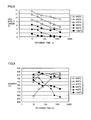
- FIG. 8 is a graph showing a relationship between the retaining time and the area ratio of carbide at each temperature.
- FIG. 9 is a graph showing a relationship between the retaining time and the hardness at each temperature.
- FIG. 10 is a graph showing the proper range of the retaining time and the retaining temperature.
- FIG. 11 is a graph showing a temperature history at one arbitrary point of a rolling contact surface when transfer quenching is executed.
- FIG. 12 is a graph showing a temperature history at one arbitrary point of the rolling contact surface.
- a formed body preparation step is first carried out as a step (S 10 ) in the method for producing an inner ring according to this embodiment.
- a steel stock of hypereutectoid steel is prepared, and working such as forging or turning is executed, whereby a formed body having a shape responsive to a desired shape of an inner ring is prepared. More specifically, a formed body having a shape responsive to a shape of an inner ring having an inner diameter of, for example, at least 1000 mm is prepared.
- SUJ3, SUJ5 or the like which is JIS-defined high carbon-chromium bearing steel can, for example, be employed as the aforementioned hypereutectoid steel.
- a normalizing step is carried out as a step (S 20 ).
- the formed body prepared in the step (S 10 ) is heated to a temperature of at least a transformation A 1 point and thereafter cooled to a temperature of less than the transformation A 1 point, whereby normalizing is executed.
- a cooling rate in the cooling in the normalizing may simply be a cooling rate at which the steel constituting the formed body does not transform into martensite, i.e., a cooling rate of less than a critical cooling rate. Hardness of the formed body after the normalizing becomes high when this cooling rate increases, and becomes low when the cooling rate decreases. Therefore, desired hardness can be supplied to the formed body by adjusting the cooling rate.
- This quench hardening step includes an induction heating step carried out as a step (S 30 ) and a cooling step carried out as a step (S 40 ).
- a coil 21 as an induction heating member is arranged to face part of a rolling contact surface 11 (annular region) which is a surface where a rolling element must roll in a formed body 10 .
- a surface of coil 21 opposed to rolling contact surface 11 has a shape along rolling contact surface 11 , as shown in FIG. 3 .
- formed body 10 is rotated on a central axis, more specifically in a direction of arrow ⁇ , while a high-frequency current is supplied to coil 21 from a power source (not shown).
- a surface layer region of formed body 10 including rolling contact surface 11 is induction-heated to a temperature of at least an A 1 point, and an annular heated region 11 A along rolling contact surface 11 is formed.
- the temperature on the surface of rolling contact surface 11 is measured with a thermometer 22 such as a radiation thermometer, and managed.
- step (S 40 ) water as a cooling liquid, for example, is injected toward the whole of formed body 10 including heated region 11 A formed in the step (S 30 ), whereby the whole of heated region 11 A is simultaneously cooled to a temperature of not more than an M s point.
- heated region 11 A transforms into martensite, and hardens.
- the temperature of heated region 11 A within a range of predetermined temperature and time in which at least a prescribed amount of carbide remains in rolling contact surface 11 and rolling contact surface 11 has a hardness of at least a prescribed hardness after the whole of heated region 11 A is cooled, and thereafter, to cool the whole of heated region 11 A.
- an inner ring (bearing ring) excellent in durability including abrasion resistance can be produced.
- the A 1 point denotes a point corresponding to a temperature at which the structure of steel starts transformation from ferrite to austenite in a case of heating the steel.
- the M s point denotes a point corresponding to a temperature at which austenized steel starts martensitation when cooled.
- a tempering step is carried out as a step (S 50 ).
- formed body 10 quench-hardened in the steps (S 30 ) and (S 40 ) is charged into a furnace, for example, heated to a temperature of not more than the A 1 point and retained for a prescribed time, whereby tempering is executed.
- the hardness of at least 60 HRC is preferably ensured although the hardness of rolling contact surface 11 lowers.
- inner ring 10 according to this embodiment produced as described above has an inner diameter d 3 of, for example, at least 1000 mm and is constituted of hypereutectoid steel such as high carbon-chromium bearing steel (SUJ3, SUJ5 or the like).
- quench-hardened layer 11 A is homogeneously formed by induction quenching along rolling contact surface 11 over the entire circumference.
- inner ring 10 according to this embodiment is a bearing ring of a rolling bearing in which quench-hardened layer 11 A is formed by induction quenching along rolling contact surface 11 over the entire circumference and durability is excellent.
- the area ratio of carbide in rolling contact surface 11 is preferably at least 5.2% and the hardness of rolling contact surface 11 is preferably at least 60 HRC.
- inner ring 10 having sufficient durability even when inner ring 10 is used in an environment where the contact stress between a rolling element and inner ring 10 is large and formation of an oil film between the rolling element and inner ring 10 is insufficient.
- Such a structure is obtained by retaining the temperature of heated region 11 A within the range of predetermined temperature and time in which the aforementioned area ratio of carbide in and the aforementioned hardness of rolling contact surface 11 can be achieved, and thereafter, cooling the whole of heated region 11 A in the aforementioned quench hardening step.
- coil 21 arranged to face part of the rolling contact surface of formed body 10 is relatively rotated along the circumferential direction in the step (S 30 ), whereby heated region 11 A is formed on formed body 10 . Therefore, it is possible to employ coil 21 small with respect to the outer shape of formed body 10 , and the production cost for a quenching apparatus can be suppressed also in a case of quench-hardening large-sized formed body 10 .
- the whole of heated region 11 A is simultaneously cooled to the temperature of not more than the M s point. Therefore, it becomes possible to form an annular quench-hardened region homogeneous in the circumferential direction, and residual stress is inhibited from concentrating on a partial region.
- a second embodiment which is another embodiment of the present invention is now described.
- a method for producing an inner ring according to the second embodiment is basically carried out similarly to the case of the first embodiment, and attains similar effects.
- the method for producing an inner ring according to the second embodiment is different from the case of the first embodiment in arrangement of coils 21 in a step (S 30 ).
- a pair of coils 21 are arranged to hold a formed body 10 therebetween in the step (S 30 ) in the second embodiment. Then, formed body 10 is rotated in a direction of arrow ⁇ , while a high-frequency current is supplied to coils 21 from a power source (not shown).
- a surface layer region of formed body 10 including a rolling contact surface 11 is induction-heated to a temperature of at least an A 1 point, and an annular heated region 11 A along rolling contact surface 11 is formed.
- plurality of (in this embodiment two) coils 21 are arranged along the circumferential direction of formed body 10 , whereby the method for producing an inner ring of a rolling bearing according to the second embodiment has become a method for producing a bearing ring capable of implementing homogeneous quench hardening by suppressing dispersion in temperature in the circumferential direction.
- coils 21 are preferably arranged at regular intervals in the circumferential direction of formed body 10 .
- temperatures on a plurality of portions (four portions here) of a rolling contact surface 11 which is a heated region are measured in the step (S 30 ) in the third embodiment. More specifically, a plurality of thermometers 22 are arranged at regular intervals along the circumferential direction of rolling contact surface 11 of a formed body 10 in the step (S 30 ) in the third embodiment.
- the temperatures on the plurality of portions are simultaneously measured in the circumferential direction of rolling contact surface 11 , whereby quench hardening can be executed by rapidly cooling formed body 10 after confirming that homogeneous heating is implemented in the circumferential direction of rolling contact surface 11 . Consequently, more homogeneous quench hardening can be implemented in the circumferential direction of rolling contact surface 11 according to the method for producing an inner ring of a rolling bearing according to the third embodiment.
- coils 21 may be rotated in the circumferential direction of formed body 10 while fixing formed body 10 , or coils 21 may be relatively rotated along the circumferential direction of formed body 10 by rotating both of coils 21 and formed body 10 .
- wires or the like supplying a current to coils 21 are necessary for coils 21 , and hence it is for the most part rational to fix coils 21 as described above.
- the length of coils 21 as induction heating members in the circumferential direction of formed body 10 can be so properly decided as to efficiently implement homogeneous heating, the same can be set to about 1/12 of the length of the region to be heated, i.e., a length of such a degree that a central angle with respect to the central axis of the formed body (bearing ring) becomes 30°, for example.
- specific conditions for the induction quenching in the present invention can be properly set in consideration of conditions such as the size and the thickness of and the material for the bearing ring (formed body), the capacity of the power source and the like.
- a step of retaining the formed body in a state where the heating is stopped is preferably provided after completion of the induction heating and before the cooling to the temperature of not more than the M s point. More specifically, dispersion in temperature in the circumferential direction on the surface of the heated region can be suppressed to about not more than 20° C. under the aforementioned conditions of the shape of the formed body and the heating, by retaining the formed body in the state where the heating is stopped for three seconds after completion of the heating, for example.
- bearing rings according to the present invention are employed as bearing rings constituting bearings for a wind turbine generator (rolling bearings for a wind turbine generator) is now described.
- a wind turbine generator 50 includes a blade 52 which is a swirler, a main shaft 51 connected to blade 52 on one end to include a center shaft of blade 52 , and a speed increaser 54 connected to another end of main shaft 51 . Further, speed increaser 54 includes an output shaft 55 , and output shaft 55 is connected to a generator 56 .
- Main shaft 51 is supported by main shaft bearings 3 which are rolling bearings for a wind turbine generator, to be rotatable on an axis.
- a plurality of (in FIG. 6 two) main shaft bearings 3 are arranged in line in the axial direction of main shaft 51 , and held by housings 53 respectively.
- Main shaft bearings 3 , housings 53 , speed increaser 54 and generator 56 are stored in a nacelle 59 which is a machinery room.
- Main shaft 51 protrudes from nacelle 59 on one end, and is connected to blade 52 .
- wind turbine generator 50 When blade 52 rotates in the circumferential direction by receiving wind power, main shaft 51 connected to blade 52 rotates on the axis while being supported by main shaft bearings 3 with respect to housings 53 .
- the rotation of main shaft 51 is transmitted to speed increaser 54 to be speeded up, and converted to rotation of output shaft 55 on an axis.
- the rotation of output shaft 55 is transmitted to generator 56 , and electromotive force is so generated by electromagnetic induction that power generation is achieved.
- each main shaft bearing 3 as a rolling bearing for a wind turbine generator includes an annular outer ring 31 as a bearing ring of the rolling bearing for a wind turbine generator, an annular inner ring 32 as another bearing ring of the rolling bearing for a wind turbine generator arranged on the inner peripheral side of outer ring 31 , and a plurality of rollers 33 arranged between outer ring 31 and inner ring 32 and held by an annular cage 34 .
- An outer ring rolling contact surface 31 A is formed on the inner peripheral surface of outer ring 31
- two inner ring rolling contact surfaces 32 A are formed on the outer peripheral surface of inner ring 32 .
- Outer ring 31 and inner ring 32 are so arranged that two inner ring rolling contact surfaces 32 A are opposed to outer ring rolling contact surface 31 A. Further, plurality of rollers 33 are in contact with outer ring rolling contact surface 31 A and inner ring rolling contact surfaces 32 A on roller contact surfaces 33 A along the respective ones of two inner ring rolling contact surfaces 32 A, and held by cage 34 and arranged at a prescribed pitch in the circumferential direction, to be rollably held on double rows (two rows) of annular raceways.
- a through-hole 31 E passing through outer ring 31 in the radial direction is formed in outer ring 31 .
- a lubricant can be supplied to a space between outer ring 31 and inner ring 32 through this through-hole 31 E.
- Outer ring 31 and inner ring 32 of main shaft bearing 3 are mutually relatively rotatable, due to the aforementioned structure.
- flange portions 32 E protruding toward outer ring 31 are formed on both ends of inner ring rolling contact surfaces 32 A in the width direction.
- Outer ring rolling contact surface 31 A has a spherical surface shape. Therefore, outer ring 31 and inner ring 32 can mutually form an angle while centering on the center of this spherical surface on a section perpendicular to the rolling direction of rollers 33 .
- main shaft bearing 3 is a double-row self-aligning roller bearing. Consequently, even in a case where main shaft 51 is deflected due to blade 52 receiving wind, housing 53 can stably rotatably hold main shaft 51 through main shaft bearing 3 .
- outer ring 31 and inner ring 32 have inner diameters of at least 1000 mm, are constituted of hypereutectoid steel, and have quench-hardened layers, formed by induction quenching, of annular shapes along the circumferential direction having uniform depths, and the surfaces of the quench-hardened layers form outer ring rolling contact surface 31 A and inner ring rolling contact surfaces 32 A respectively. Consequently, aforementioned outer ring 31 and inner ring 32 have become large-sized bearing rings excellent in durability, in which quench-hardened layers are homogeneously formed by induction quenching along the rolling contact surfaces over the entire circumference while the cost for heat treatment is suppressed, and have become bearing rings constituting a bearing for a wind turbine generator usable also in a severe environment.
- inner ring rolling contact surface 32 A serves as a load region over the entire circumference.
- the quench-hardened layer is formed by induction quenching along inner ring rolling contact surface 32 A over the entire circumference. Therefore, even when inner ring rolling contact surface 32 A serves as the load region over the entire circumference, inner ring 32 has sufficient durability.
- main shaft bearing 3 may be used in an environment where a value of oil film parameter ⁇ is not more than 1 due to repeated rotation and stop of main shaft 51 , and the like.
- outer ring 31 and inner ring 32 constituting main shaft bearing 3 are bearing rings according to the present invention excellent in durability including abrasion resistance. Therefore, even in a case of use in such a severe environment, main shaft bearing 3 has sufficient durability.
- Main shaft bearing 3 excellent in durability is also suitable as a main shaft bearing for offshore wind power generation where repair is difficult.
- the bearings for a wind turbine generator have been described as examples of the large-sized rolling bearing in the aforementioned fourth embodiment, application to another large-sized rolling bearing is also possible. More specifically, the bearing ring according to the present invention can be suitably applied to a bearing ring of a rolling bearing for a CT scanner supporting a rotatable mounting on which an X-ray irradiation portion of a CT scanner is set to be rotatable with respect to a fixed mounting arranged to be opposed to the rotatable mounting, for example.
- the bearing ring according to the present invention is applicable to a bearing ring of an arbitrary rolling bearing such as a deep groove ball bearing, an angular contact ball bearing, a cylindrical roller bearing, a tapered roller bearing, a self-aligning roller bearing or a thrust ball bearing, for example.
- an arbitrary rolling bearing such as a deep groove ball bearing, an angular contact ball bearing, a cylindrical roller bearing, a tapered roller bearing, a self-aligning roller bearing or a thrust ball bearing, for example.
- a fifth embodiment which is one embodiment of the present invention is first described with reference to a method for producing an inner ring which is a bearing ring of a rolling bearing.
- a formed body preparation step is first carried out as a step (S 10 ) in the method for producing an inner ring according to this embodiment.
- a steel stock containing at least 0.95 mass % and not more than 1.10 mass % of carbon, at least 0.40 mass % and not more than 0.70 mass % of silicon, at least 0.90 mass % and not more than 1.15 mass % of manganese, and at least 0.90 mass % and not more than 1.20 mass % of chromium with the rest consisting of iron and an impurity is prepared and working such as forging or turning is executed, whereby a formed body having a shape responsive to a desired shape of an inner ring is prepared. More specifically, a formed body responsive to the shape of an inner ring having an inner diameter of at least 1000 mm is prepared.
- a steel stock to which at least 0.10 mass % and not more than 0.25 mass % of molybdenum is added in addition to the aforementioned alloy components may be employed.
- JIS SUJ3, SUJ5 or the like can be listed, for example.
- a normalizing step is carried out as a step (S 20 ).
- the formed body prepared in the step (S 10 ) is heated to a temperature of at least a transformation A 1 point and thereafter cooled to a temperature of less than the transformation A 1 point, whereby normalizing is executed.
- a cooling rate in the cooling in the normalizing may simply be a cooling rate at which the steel constituting the formed body does not transform into martensite, i.e., a cooling rate of less than a critical cooling rate. Hardness of the formed body after the normalizing becomes high when this cooling rate increases, and becomes low when the cooling rate decreases. Therefore, desired hardness can be supplied to the formed body by adjusting the cooling rate.
- This quench hardening step includes an induction heating step carried out as a step (S 30 ) and a cooling step carried out as a step (S 40 ).
- a coil 21 as an induction heating member is arranged to face part of a rolling contact surface 11 (annular region) which is a surface where a rolling element must roll in a formed body 10 .
- a surface of coil 21 opposed to rolling contact surface 11 has a shape along rolling contact surface 11 , as shown in FIG. 3 .
- formed body 10 is rotated on a central axis, more specifically in a direction of arrow ⁇ , while a high-frequency current is supplied to coil 21 from a power source (not shown).
- a surface layer region of formed body 10 including rolling contact surface 11 is induction-heated to a temperature of at least the A 1 point, and an annular heated region 11 A along rolling contact surface 11 is formed.
- the temperature on the surface of rolling contact surface 11 is measured with a thermometer 22 such as a radiation thermometer, and managed.
- step (S 40 ) water as a cooling liquid, for example, is injected toward the whole of formed body 10 including heated region 11 A formed in the step (S 30 ), whereby the whole of heated region 11 A is simultaneously cooled to a temperature of not more than an M s point.
- heated region 11 A transforms into martensite, and hardens.
- a tempering step is carried out as a step (S 50 ).
- formed body 10 quench-hardened in the steps (S 30 ) and (S 40 ) is charged into a furnace, for example, heated to a temperature of not more than the A 1 point and retained for a prescribed time, whereby tempering is executed.
- coil 21 arranged to face part of the rolling contact surface of formed body 10 is relatively rotated along the circumferential direction in the step (S 30 ), whereby heated region 11 A is formed on formed body 10 . Therefore, it is possible to employ coil 21 small with respect to the outer shape of formed body 10 , and the production cost for a quenching apparatus can be suppressed also in a case of quench-hardening large-sized formed body 10 . According to this embodiment, further, the whole of heated region 11 A is simultaneously cooled to the temperature of not more than the M s point. Therefore, it becomes possible to form an annular quench-hardened region homogeneous in the circumferential direction, and residual stress is inhibited from concentrating on a partial region.
- the method for producing an inner ring according to this embodiment has become a method for producing a bearing ring capable of homogeneously forming a quench-hardened layer by induction quenching along a rolling contact surface over the entire circumference while suppressing the production cost for a quenching apparatus.
- step (S 20 ) is not an essential step in the method for producing a bearing ring according to the present invention
- the hardness of an unhardened region (region other than the quench-hardened layer) of the produced bearing ring can be adjusted by carrying out this. It is also possible to achieve the adjustment of the hardness of the unhardened region by executing quenching and tempering, in place of the step (S 20 ).
- the steel having a high carbon content and having the aforementioned component composition exhibiting high quenchability is employed as the material in this embodiment, and hence quench cracking easily takes place. Therefore, normalizing is preferably executed as the step (S 20 ) for hardness adjustment of the unhardened region.
- shot blasting may be executed while formed body 10 is cooled, by spraying hard particles onto formed body 10 along with gas.
- the shot blasting can be executed simultaneously with air-blast cooling at the time of the normalizing. Therefore, scales formed on the surface layer portion of formed body 10 due to heating in the normalizing are removed, and characteristic reduction of the bearing ring resulting from formation of the scales or reduction of thermal conductivity resulting from formation of the scales is suppressed.
- the hard particles projection material
- metal particles made of steel or cast iron can be employed, for example.
- While formed body 10 may rotate at least once in the aforementioned step (S 30 ), the same preferably rotates a plurality of times, in order to implement more homogeneous quench hardening by suppressing dispersion in temperature in the circumferential direction.
- coil 21 as an induction heating member preferably relatively rotates at least twice along the circumferential direction of the rolling contact surface of formed body 10 .
- a sixth embodiment which is a further embodiment of the present invention is now described.
- a method for producing an inner ring according to the sixth embodiment is basically carried out similarly to the case of the fifth embodiment, and attains similar effects.
- the method for producing an inner ring according to the sixth embodiment is different from the case of the fifth embodiment in arrangement of coils 21 in a step (S 30 ).
- a pair of coils 21 are arranged to hold a formed body 10 therebetween in the step (S 30 ) in the sixth embodiment. Then, formed body 10 is rotated in a direction of arrow ⁇ , and a high-frequency current is supplied to coils 21 from a power source (not shown). Thus, a surface layer region of formed body 10 including a rolling contact surface 11 is induction-heated to a temperature of at least an A 1 point, and an annular heated region 11 A along rolling contact surface 11 is formed.
- a plurality of (in this embodiment two) coils 21 are arranged along the circumferential direction of formed body 10 , whereby the method for producing an inner ring of a rolling bearing according to the sixth embodiment has become a method for producing a bearing ring capable of implementing homogeneous quench hardening by suppressing dispersion in temperature in the circumferential direction.
- coils 21 are preferably arranged at regular intervals in the circumferential direction of formed body 10 .
- a seventh embodiment which is a further embodiment of the present invention is now described.
- a method for producing an inner ring according to the seventh embodiment is basically carried out similarly to the cases of the fifth and sixth embodiments, and attains similar effects.
- the method for producing an inner ring according to the seventh embodiment is different from the cases of the fifth and sixth embodiments in arrangement of thermometers 22 in a step (S 30 ).
- temperatures on a plurality of portions (four portions here) of a rolling contact surface 11 which is a heated region are measured in the step (S 30 ) in the seventh embodiment. More specifically, a plurality of thermometers 22 are arranged at regular intervals along the circumferential direction of rolling contact surface 11 of a formed body 10 in the step (S 30 ) in the seventh embodiment.
- the temperatures on the plurality of portions are simultaneously measured in the circumferential direction of rolling contact surface 11 , whereby quench hardening can be executed by rapidly cooling formed body 10 after confirming that homogeneous heating is implemented in the circumferential direction of rolling contact surface 11 . Consequently, more homogeneous quench hardening can be implemented in the circumferential direction of rolling contact surface 11 according to the method for producing an inner ring of a rolling bearing according to the seventh embodiment.
- coils 21 may be rotated in the circumferential direction of formed body 10 while fixing formed body 10 , or coils 21 may be relatively rotated along the circumferential direction of formed body 10 by rotating both of coils 21 and formed body 10 .
- wires or the like supplying a current to coils 21 are necessary for coils 21 , and hence it is for the most part rational to fix coils 21 as described above.
- a bearing ring to which the present invention is applicable is not restricted to this, but may be an outer ring of a radial rolling bearing or a bearing ring of a thrust bearing, for example.
- coils 21 may be arranged to face a rolling contact surface formed on an inner peripheral side of a formed body.
- coils 21 may be arranged to face a rolling contact surface formed on an end surface side of a formed body.
- the length of coils 21 as induction heating members in the circumferential direction of formed body 10 can be so properly decided as to efficiently implement homogeneous heating, the same can be set to about 1/12 of the length of the region to be heated, i.e., a length of such a degree that a central angle with respect to the central axis of the formed body (bearing ring) becomes 30°, for example.
- specific conditions for the induction quenching in the present invention can be properly set in consideration of conditions such as the size and the thickness of and the material for the bearing ring (formed body), the capacity of the power source and the like.
- a step of retaining the formed body in a state where the heating is stopped is preferably provided after completion of the induction heating and before the cooling to the temperature of not more than the M s point. More specifically, dispersion in temperature in the circumferential direction on the surface of the heated region can be suppressed to about not more than 20° C. under the aforementioned conditions of the shape of the formed body and the heating, by retaining the formed body in the state where the heating is stopped for three seconds after completion of the heating, for example.
- bearing rings according to the present invention are employed as bearing rings constituting bearings for a wind turbine generator (rolling bearings for a wind turbine generator) is now described.
- a wind turbine generator 50 includes a blade 52 which is a swirler, a main shaft 51 connected to blade 52 on one end to include a center shaft of blade 52 , and a speed increaser 54 connected to another end of main shaft 51 . Further, speed increaser 54 includes an output shaft 55 , and output shaft 55 is connected to a generator 56 .
- Main shaft 51 is supported by main shaft bearings 3 which are rolling bearings for a wind turbine generator, to be rotatable on an axis.
- a plurality of (in FIG. 6 two) main shaft bearings 3 are arranged in line in the axial direction of main shaft 51 , and held by housings 53 respectively.
- Main shaft bearings 3 , housings 53 , speed increaser 54 and generator 56 are stored in a nacelle 59 which is a machinery room.
- Main shaft 51 protrudes from nacelle 59 on one end, and is connected to blade 52 .
- each main shaft bearing 3 as a rolling bearing for a wind turbine generator includes an annular outer ring 31 as a bearing ring of the rolling bearing for a wind turbine generator, an annular inner ring 32 as another bearing ring of the rolling bearing for a wind turbine generator arranged on the inner peripheral side of outer ring 31 , and a plurality of rollers 33 arranged between outer ring 31 and inner ring 32 and held by an annular cage 34 .
- An outer ring rolling contact surface 31 A is formed on the inner peripheral surface of outer ring 31
- two inner ring rolling contact surfaces 32 A are formed on the outer peripheral surface of inner ring 32 .
- Outer ring 31 and inner ring 32 are so arranged that two inner ring rolling contact surfaces 32 A are opposed to outer ring rolling contact surface 31 A. Further, plurality of rollers 33 are in contact with outer ring rolling contact surface 31 A and inner ring rolling contact surfaces 32 A on roller contact surfaces 33 A along the respective ones of two inner ring rolling contact surfaces 32 A, and held by cage 34 and arranged at a prescribed pitch in the circumferential direction, to be rollably held on double rows (two rows) of annular raceways.
- a through-hole 31 E passing through outer ring 31 in the radial direction is formed in outer ring 31 .
- a lubricant can be supplied to a space between outer ring 31 and inner ring 32 through this through-hole 31 E.
- Outer ring 31 and inner ring 32 of main shaft bearing 3 are mutually relatively rotatable, due to the aforementioned structure.
- main shaft 51 connected to blade 52 passes through inner ring 32 of main shaft bearing 3 , is in contact with an inner peripheral surface 32 F of the inner ring on an outer peripheral surface 51 A, and fixed to inner ring 32 .
- Outer ring 31 of main shaft bearing 3 is fitted to come into contact with an inner wall 53 A of a through-hole formed in housing 53 on an outer peripheral surface 31 F, and fixed to housing 53 .
- Main shaft 51 connected to blade 52 is rotatable on the axis with respect to outer ring 31 and housing 53 integrally with inner ring 32 , due to the aforementioned structure.
- flange portions 32 E protruding toward outer ring 31 are formed on both ends of inner ring rolling contact surfaces 32 A in the width direction.
- Outer ring rolling contact surface 31 A has a spherical surface shape. Therefore, outer ring 31 and inner ring 32 can mutually form an angle while centering on the center of this spherical surface on a section perpendicular to the rolling direction of rollers 33 .
- main shaft bearing 3 is a double-row self-aligning roller bearing. Consequently, even in a case where main shaft 51 is deflected due to blade 52 receiving wind, housing 53 can stably rotatably hold main shaft 51 through main shaft bearing 3 .
- Outer ring 31 and inner ring 32 as bearing rings of a rolling bearing for a wind turbine generator according to the eighth embodiment are produced by the method for producing a bearing ring according to the aforementioned fifth to seventh embodiments, for example.
- Outer ring 31 and inner ring 32 are bearing rings of a rolling bearing for a wind turbine generator having inner diameters of at least 1000 mm.
- quench-hardened layers are homogeneously formed by induction quenching along outer ring rolling contact surface 31 A and inner ring rolling contact surfaces 32 A over the entire circumference.
- outer ring 31 and inner ring 32 have inner diameters of at least 1000 mm, and have quench-hardened layers, formed by induction quenching, of annular shapes along the circumferential direction having uniform depths, and the surfaces of the quench-hardened layers form outer ring rolling contact surface 31 A and inner ring rolling contact surfaces 32 A respectively. Consequently, aforementioned outer ring 31 and inner ring 32 have become large-sized bearing rings in which quench-hardened layers are homogeneously formed by induction quenching along the rolling contact surfaces over the entire circumference while the cost for heat treatment is suppressed, and have become bearing rings constituting a bearing for a wind turbine generator usable also in a severe environment.
- the method for producing a bearing ring according to the present invention is suitable for production of a bearing ring of a large-sized rolling bearing. While the bearings for a wind turbine generator have been described as examples of the large-sized rolling bearing in the aforementioned eighth embodiment, application to another large-sized rolling bearing is also possible. More specifically, the method for producing a bearing ring according to the present invention can be suitably applied to production of a bearing ring of a rolling bearing for a CT scanner supporting a rotatable mounting on which an X-ray irradiation portion of a CT scanner is set to be rotatable with respect to a fixed mounting arranged to be opposed to the rotatable mounting, for example.
- the method for producing a bearing ring according to the present invention is applicable to a bearing ring of an arbitrary rolling bearing such as a deep groove ball bearing, an angular contact ball bearing, a cylindrical roller bearing, a tapered roller bearing, a self-aligning roller bearing or a thrust ball bearing, for example.
- a ninth embodiment which is an embodiment of the present invention is described with reference to a method for producing an inner ring which is a bearing ring of a rolling bearing.
- a formed body preparation step is first carried out as a step (S 10 ) in the method for producing an inner ring according to this embodiment.
- a steel stock of hypereutectoid steel is prepared, and working such as forging or turning is executed, whereby a formed body having a shape responsive to a desired shape of an inner ring is prepared. More specifically, a formed body having a shape responsive to a shape of an inner ring having an inner diameter of, for example, at least 1000 mm is prepared.
- SUJ3, SUJ5 or the like which is JIS-defined high carbon-chromium bearing steel can, for example, be employed as the aforementioned hypereutectoid steel.
- a normalizing step is carried out as a step (S 20 ).
- the formed body prepared in the step (S 10 ) is heated to a temperature of at least a transformation A 1 point and thereafter cooled to a temperature of less than the transformation A 1 point, whereby normalizing is executed.
- a cooling rate in the cooling in the normalizing may simply be a cooling rate at which the steel constituting the formed body does not transform into martensite, i.e., a cooling rate of less than a critical cooling rate. Hardness of the formed body after the normalizing becomes high when this cooling rate increases, and becomes low when the cooling rate decreases. Therefore, desired hardness can be supplied to the formed body by adjusting the cooling rate.
- This quench hardening step includes an induction heating step carried out as a step (S 30 ) and a cooling step carried out as a step (S 40 ).
- a coil 21 as an induction heating member is arranged to face part of a rolling contact surface 11 (annular region) which is a surface where a rolling element must roll in a formed body 10 .
- a surface of coil 21 opposed to rolling contact surface 11 has a shape along rolling contact surface 11 , as shown in FIG. 3 .
- formed body 10 is rotated on a central axis, more specifically in a direction of arrow ⁇ , while a high-frequency current is supplied to coil 21 from a power source (not shown).
- a surface layer region of formed body 10 including rolling contact surface 11 is induction-heated to a temperature of at least an A 1 point, and an annular heated region 11 A along rolling contact surface 11 is formed.
- the temperature on the surface of rolling contact surface 11 is measured with a thermometer 22 such as a radiation thermometer, and managed.
- step (S 40 ) water as a cooling liquid, for example, is injected toward the whole of formed body 10 including heated region 11 A formed in the step (S 30 ), whereby the whole of heated region 11 A is simultaneously cooled to a temperature of not more than an M s point.
- heated region 11 A transforms into martensite, and hardens.
- the temperature of heated region 11 A within a range of predetermined temperature and time in which at least a prescribed amount of carbide remains in rolling contact surface 11 and rolling contact surface 11 has a hardness of at least a prescribed hardness after the whole of heated region 11 A is cooled, and thereafter, to cool the whole of heated region 11 A.
- an inner ring (bearing ring) excellent in durability including abrasion resistance can be produced.
- a tempering step is carried out as a step (S 50 ).
- formed body 10 quench-hardened in the steps (S 30 ) and (S 40 ) is charged into a furnace, for example, heated to a temperature of not more than the A 1 point and retained for a prescribed time, whereby tempering is executed.
- a finishing step is carried out as a step (S 60 ).
- finishing such as polishing is executed on rolling contact surface 11 , for example.
- inner ring 10 according to this embodiment produced as described above has an inner diameter d 3 of, for example, at least 1000 mm and is constituted of hypereutectoid steel such as high carbon-chromium bearing steel (SUJ3, SUJ5 or the like).
- quench-hardened layer 11 A is homogeneously formed by induction quenching along rolling contact surface 11 over the entire circumference.
- inner ring 10 according to this embodiment is a bearing ring of a rolling bearing in which quench-hardened layer 11 A is formed by induction quenching along rolling contact surface 11 over the entire circumference and durability is excellent.
- the area ratio of carbide in rolling contact surface 11 is preferably at least 5.2% and the hardness of rolling contact surface 11 is preferably at least 62 HRC.
- inner ring 10 having sufficient durability even when inner ring 10 is used in an environment where the contact stress between a rolling element and inner ring 10 is large and formation of an oil film between the rolling element and inner ring 10 is insufficient.
- Such a structure is obtained by retaining the temperature of heated region 11 A within the range of predetermined temperature and time in which the aforementioned area ratio of carbide in and the aforementioned hardness of rolling contact surface 11 can be achieved, and thereafter, cooling the whole of heated region 11 A in the aforementioned quench hardening step.
- coil 21 arranged to face part of the rolling contact surface of formed body 10 is relatively rotated along the circumferential direction in the step (S 30 ), whereby heated region 11 A is formed on formed body 10 . Therefore, it is possible to employ coil 21 small with respect to the outer shape of formed body 10 , and the production cost for a quenching apparatus can be suppressed also in a case of quench-hardening large-sized formed body 10 .
- the whole of heated region 11 A is simultaneously cooled to the temperature of not more than the M s point. Therefore, it becomes possible to form an annular quench-hardened region homogeneous in the circumferential direction, and residual stress is inhibited from concentrating on a partial region.
- hypereutectoid steel capable of implementing sufficiently high hardness and a sufficient amount of carbide by quench hardening is employed as a material. Consequently, according to the method for producing an inner ring according to this embodiment, the inner ring (bearing ring) in which the quench-hardened layer is homogeneously formed by induction quenching along the rolling contact surface over the entire circumference and durability including abrasion resistance is excellent can be produced while suppressing the production cost for the quenching apparatus.
- step (S 20 ) is not an essential step in the method for producing a bearing ring according to the present invention
- the hardness of an unhardened region (region other than the quench-hardened layer) of the produced bearing ring can be adjusted by carrying out this.
- shot blasting may be executed while formed body 10 is cooled, by spraying hard particles onto formed body 10 along with gas.
- the shot blasting can be executed simultaneously with air-blast cooling at the time of the normalizing. Therefore, scales formed on the surface layer portion of formed body 10 due to heating in the normalizing are removed, and characteristic reduction of the bearing ring resulting from formation of the scales or reduction of thermal conductivity resulting from formation of the scales is suppressed.
- the hard particles projection material
- metal particles made of steel or cast iron can be employed, for example.
- While formed body 10 may rotate at least once in the aforementioned step (S 30 ), the same preferably rotates a plurality of times, in order to implement more homogeneous quench hardening by suppressing dispersion in temperature in the circumferential direction.
- coil 21 as an induction heating member preferably relatively rotates at least twice along the circumferential direction of the rolling contact surface of formed body 10 .
- a tenth embodiment which is another embodiment of the present invention is now described.
- a method for producing an inner ring according to the tenth embodiment is basically carried out similarly to the case of the ninth embodiment, and attains similar effects.
- the method for producing an inner ring according to the tenth embodiment is different from the case of the ninth embodiment in arrangement of coils 21 in a step (S 30 ).
- a pair of coils 21 are arranged to hold a formed body 10 therebetween in the step (S 30 ) in the tenth embodiment. Then, formed body 10 is rotated in a direction of arrow ⁇ , while a high-frequency current is supplied to coils 21 from a power source (not shown).
- a surface layer region of formed body 10 including a rolling contact surface 11 is induction-heated to a temperature of at least an A 1 point, and an annular heated region 11 A along rolling contact surface 11 is formed.
- plurality of (in this embodiment two) coils 21 are arranged along the circumferential direction of formed body 10 , whereby the method for producing an inner ring of a rolling bearing according to the tenth embodiment has become a method for producing a bearing ring capable of implementing homogeneous quench hardening by suppressing dispersion in temperature in the circumferential direction.
- coils 21 are preferably arranged at regular intervals in the circumferential direction of formed body 10 .
- a method for producing an inner ring according to the eleventh embodiment is basically carried out similarly to the cases of the ninth and tenth embodiments, and attains similar effects. However, the method for producing an inner ring according to the eleventh embodiment is different from the cases of the ninth and tenth embodiments in arrangement of thermometers 22 in a step (S 30 ).
- temperatures on a plurality of portions (four portions here) of a rolling contact surface 11 which is a heated region are measured in the step (S 30 ) in the eleventh embodiment. More specifically, a plurality of thermometers 22 are arranged at regular intervals along the circumferential direction of rolling contact surface 11 of a formed body 10 in the step (S 30 ) in the eleventh embodiment.
- the temperatures on the plurality of portions are simultaneously measured in the circumferential direction of rolling contact surface 11 , whereby quench hardening can be executed by rapidly cooling formed body 10 after confirming that homogeneous heating is implemented in the circumferential direction of rolling contact surface 11 . Consequently, more homogeneous quench hardening can be implemented in the circumferential direction of rolling contact surface 11 according to the method for producing an inner ring of a rolling bearing according to the eleventh embodiment.
- coils 21 may be rotated in the circumferential direction of formed body 10 while fixing formed body 10 , or coils 21 may be relatively rotated along the circumferential direction of formed body 10 by rotating both of coils 21 and formed body 10 .
- wires or the like supplying a current to coils 21 are necessary for coils 21 , and hence it is for the most part rational to fix coils 21 as described above.
- a bearing ring to which the present invention is applicable is not restricted to this, but may be an outer ring of a radial rolling bearing or a bearing ring of a thrust bearing, for example.
- coils 21 may be arranged to face a rolling contact surface formed on an inner peripheral side of a formed body.
- coils 21 may be arranged to face a rolling contact surface formed on an end surface side of a formed body.
- the length of coils 21 as induction heating members in the circumferential direction of formed body 10 can be so properly decided as to efficiently implement homogeneous heating, the same can be set to about 1/12 of the length of the region to be heated, i.e., a length of such a degree that a central angle with respect to the central axis of the formed body (bearing ring) becomes 30°, for example.
- specific conditions for the induction quenching in the present invention can be properly set in consideration of conditions such as the size and the thickness of and the material for the bearing ring (formed body), the capacity of the power source and the like.
- a step of retaining the formed body in a state where the heating is stopped is preferably provided after completion of the induction heating and before the cooling to the temperature of not more than the M s point. More specifically, dispersion in temperature in the circumferential direction on the surface of the heated region can be suppressed to about not more than 20° C. under the aforementioned conditions of the shape of the formed body and the heating, by retaining the formed body in the state where the heating is stopped for three seconds after completion of the heating, for example.
- bearing rings according to the present invention are employed as bearing rings constituting bearings for a wind turbine generator (rolling bearings for a wind turbine generator) is now described.
- a wind turbine generator 50 includes a blade 52 which is a swirler, a main shaft 51 connected to blade 52 on one end to include a center shaft of blade 52 , and a speed increaser 54 connected to another end of main shaft 51 . Further, speed increaser 54 includes an output shaft 55 , and output shaft 55 is connected to a generator 56 .
- Main shaft 51 is supported by main shaft bearings 3 which are rolling bearings for a wind turbine generator, to be rotatable on an axis.
- a plurality of (in FIG. 6 two) main shaft bearings 3 are arranged in line in the axial direction of main shaft 51 , and held by housings 53 respectively.
- Main shaft bearings 3 , housings 53 , speed increaser 54 and generator 56 are stored in a nacelle 59 which is a machinery room.
- Main shaft 51 protrudes from nacelle 59 on one end, and is connected to blade 52 .
- wind turbine generator 50 When blade 52 rotates in the circumferential direction by receiving wind power, main shaft 51 connected to blade 52 rotates on the axis while being supported by main shaft bearings 3 with respect to housings 53 .
- the rotation of main shaft 51 is transmitted to speed increaser 54 to be speeded up, and converted to rotation of output shaft 55 on an axis.
- the rotation of output shaft 55 is transmitted to generator 56 , and electromotive force is so generated by electromagnetic induction that power generation is achieved.
- each main shaft bearing 3 as a rolling bearing for a wind turbine generator includes an annular outer ring 31 as a bearing ring of the rolling bearing for a wind turbine generator, an annular inner ring 32 as another bearing ring of the rolling bearing for a wind turbine generator arranged on the inner peripheral side of outer ring 31 , and a plurality of rollers 33 arranged between outer ring 31 and inner ring 32 and held by an annular cage 34 .
- An outer ring rolling contact surface 31 A is formed on the inner peripheral surface of outer ring 31
- two inner ring rolling contact surfaces 32 A are formed on the outer peripheral surface of inner ring 32 .
- Outer ring 31 and inner ring 32 are so arranged that two inner ring rolling contact surfaces 32 A are opposed to outer ring rolling contact surface 31 A. Further, plurality of rollers 33 are in contact with outer ring rolling contact surface 31 A and inner ring rolling contact surfaces 32 A on roller contact surfaces 33 A along the respective ones of two inner ring rolling contact surfaces 32 A, and held by cage 34 and arranged at a prescribed pitch in the circumferential direction, to be rollably held on double rows (two rows) of annular raceways.
- a through-hole 31 E passing through outer ring 31 in the radial direction is formed in outer ring 31 .
- a lubricant can be supplied to a space between outer ring 31 and inner ring 32 through this through-hole 31 E.
- Outer ring 31 and inner ring 32 of main shaft bearing 3 are mutually relatively rotatable, due to the aforementioned structure.
- main shaft 51 connected to blade 52 passes through inner ring 32 of main shaft bearing 3 , is in contact with an inner peripheral surface 32 F of the inner ring on an outer peripheral surface 51 A, and fixed to inner ring 32 .
- Outer ring 31 of main shaft bearing 3 is fitted to come into contact with an inner wall 53 A of a through-hole formed in housing 53 on an outer peripheral surface 31 F, and fixed to housing 53 .
- Main shaft 51 connected to blade 52 is rotatable on the axis with respect to outer ring 31 and housing 53 integrally with inner ring 32 , due to the aforementioned structure.
- flange portions 32 E protruding toward outer ring 31 are formed on both ends of inner ring rolling contact surfaces 32 A in the width direction.
- Outer ring rolling contact surface 31 A has a spherical surface shape. Therefore, outer ring 31 and inner ring 32 can mutually form an angle while centering on the center of this spherical surface on a section perpendicular to the rolling direction of rollers 33 .
- main shaft bearing 3 is a double-row self-aligning roller bearing. Consequently, even in a case where main shaft 51 is deflected due to blade 52 receiving wind, housing 53 can stably rotatably hold main shaft 51 through main shaft bearing 3 .
- Outer ring 31 and inner ring 32 as bearing rings of a rolling bearing for a wind turbine generator according to the twelfth embodiment are produced by the method for producing a bearing ring according to the aforementioned ninth to eleventh embodiments, for example, and have a structure similar to that of inner ring 10 in the aforementioned ninth embodiment.
- outer ring 31 and inner ring 32 are bearing rings of a rolling bearing for a wind turbine generator having inner diameters of at least 1000 mm.
- Outer ring 31 and inner ring 32 are constituted of hypereutectoid steel and quench-hardened layers are homogeneously formed by induction quenching along outer ring rolling contact surface 31 A and inner ring rolling contact surfaces 32 A over the entire circumference.
- outer ring 31 and inner ring 32 have inner diameters of at least 1000 mm, and are constituted of hypereutectoid steel, and have quench-hardened layers, formed by induction quenching, of annular shapes along the circumferential direction having uniform depths, and the surfaces of the quench-hardened layers form outer ring rolling contact surface 31 A and inner ring rolling contact surfaces 32 A respectively.
- outer ring 31 and inner ring 32 have become large-sized bearing rings excellent in durability, in which quench-hardened layers are homogeneously formed by induction quenching along the rolling contact surfaces over the entire circumference while the cost for heat treatment is suppressed, and have become bearing rings constituting a bearing for a wind turbine generator usable also in a severe environment.
- inner ring rolling contact surface 32 A serves as a load region over the entire circumference.
- the quench-hardened layer is formed by induction quenching along inner ring rolling contact surface 32 A over the entire circumference. Therefore, even when inner ring rolling contact surface 32 A serves as the load region over the entire circumference, inner ring 32 has sufficient durability.
- main shaft bearing 3 may be used in an environment where a value of oil film parameter ⁇ is not more than 1 due to repeated rotation and stop of main shaft 51 , and the like.
- outer ring 31 and inner ring 32 constituting main shaft bearing 3 are bearing rings according to the present invention excellent in durability including abrasion resistance. Therefore, even in a case of use in such a severe environment, main shaft bearing 3 has sufficient durability.
- Main shaft bearing 3 excellent in durability is also suitable as a main shaft bearing for offshore wind power generation where repair is difficult.
- the bearings for a wind turbine generator have been described as examples of the large-sized rolling bearing in the aforementioned twelfth embodiment, application to another large-sized rolling bearing is also possible. More specifically, the bearing ring according to the present invention can be suitably applied to a bearing ring of a rolling bearing for a CT scanner supporting a rotatable mounting on which an X-ray irradiation portion of a CT scanner is set to be rotatable with respect to a fixed mounting arranged to be opposed to the rotatable mounting, for example.
- the bearing ring according to the present invention is applicable to a bearing ring of an arbitrary rolling bearing such as a deep groove ball bearing, an angular contact ball bearing, a cylindrical roller bearing, a tapered roller bearing, a self-aligning roller bearing or a thrust ball bearing, for example.
- an arbitrary rolling bearing such as a deep groove ball bearing, an angular contact ball bearing, a cylindrical roller bearing, a tapered roller bearing, a self-aligning roller bearing or a thrust ball bearing, for example.
- test specimen was also prepared by employing JIS S55C as a material and adopting a similar method (Comparative Example).
- the specific abrasion rate of the test specimen in Example is about 63% of the specific abrasion rate of the test specimen in Comparative Example. This is conceivably due to the fact that the area ratio of carbide in the test specimen in Comparative Example is 0.1%, whereas the area ratio of carbide in the test specimen in Example is 8.8%. Thus, it has been confirmed that according to the bearing ring of the rolling bearing according to the present invention, high abrasion resistance can be ensured because a sufficient amount of carbide is contained.
- the area ratio of carbide is preferably at least 2%, and more preferably at least 4%.
- the area ratio of carbide is preferably not more than 11%, and more preferably not more than 9%.
- test specimen constituted of JIS SUJ5 was prepared. Then, this test specimen was retained for each time of 10, 30, 60, 300, 600, and 1800 seconds at each temperature of 800, 850, 875, 900, 950, and 1000° C. at a temperature rise rate of 3° C./sec by high-frequency heating, and thereafter, was rapidly cooled, whereby the test specimen was quench-hardened. Then, the obtained test specimen was cut and the cut surface was polished. Furthermore, the section was corroded using picral (picric acid alcohol solution) as a corrosive liquid and the area ratio of carbide observed in the metal structure was investigated. In addition, the obtained test specimen was cut and the hardness was investigated using a Vickers hardness tester.
- FIGS. 8 and 9 The investigation result is shown in FIGS. 8 and 9 .
- the horizontal axis indicates the retaining time.
- the vertical axis in FIG. 8 indicates the area ratio of carbide, and the vertical axis in FIG. 9 indicates the Vickers hardness.
- the area ratio of carbide becomes smaller as the heating temperature becomes higher, and becomes smaller as the retaining time becomes longer. This is conceivably because a larger amount of carbide melts into the base as the heating temperature becomes higher, and a larger amount of carbide melts into the base as the retaining time becomes longer.
- the hardness becomes higher as the retaining time becomes longer.
- the heating temperature range of 875 to 900° C. the hardness becomes higher as the retaining time becomes longer, and thereafter, the hardness becomes lower as the retaining time becomes further longer.
- the heating temperature range of 950 to 1000° C. the hardness becomes lower as the retaining time becomes longer.
- FIG. 10 is a diagram showing this range.
- the hardness of 62 HRC corresponds to the hardness of 746 HV.
- the horizontal axis indicates the retaining time
- the vertical axis indicates the retaining temperature.
- a simulation of checking an advantage of the method for producing a bearing ring according to the aforementioned embodiments was performed. On the assumption of the case of quench-hardening a bearing ring having an outer diameter of ⁇ 2000 mm, a temperature history at one arbitrary point on the rolling contact surface was calculated.
- a method for quench hardening As a method for quench hardening, the following two methods were studied: a method for executing high-frequency induction heating with a coil arranged to be opposed to part of the rolling contact surface in the circumferential direction, and injecting a cooling liquid toward the heated region immediately after passage of the coil thereby successively quench-hardening this region (transfer quenching); and a method for relatively rotating a coil arranged to face part of the rolling contact surface along the circumferential direction, forming an annular heated region and simultaneously cooling the whole of the heated region to a temperature of not more than the M s point (Example; corresponding to the method for producing a bearing ring according to the aforementioned embodiments).
- the aforementioned transfer quenching corresponds to the aforementioned method described in PTD 2.
- the quench-hardening method in Example corresponding to the method for producing a bearing ring according to the aforementioned embodiments
- the one point on the rolling contact surface is heated to a temperature of at least the transformation A 1 point capable of quench hardening and thereafter retained for a long time with small change in temperature (the cooling to a temperature of not more than the M s point is not shown in the figure because it is executed after the time further elapses). Therefore, in the method in Example, the amount of dissolved carbon can be easily controlled. Consequently, when the quenching method in Example is employed, proper quench hardening can be easily achieved.
- a method for producing a bearing ring, a bearing ring, and a rolling bearing according to the present invention can be applied particularly advantageously to a method for producing a bearing ring which is required to homogeneously form a quench-hardened layer along a rolling contact surface over the entire circumference, while suppressing the production cost for a quenching apparatus, a bearing ring of a rolling bearing which is required to form a quench-hardened layer along a rolling contact surface over the entire circumference, and a rolling bearing including the bearing ring.
Landscapes
- Chemical & Material Sciences (AREA)
- Engineering & Computer Science (AREA)
- Mechanical Engineering (AREA)
- Organic Chemistry (AREA)
- Metallurgy (AREA)
- Materials Engineering (AREA)
- Thermal Sciences (AREA)
- Crystallography & Structural Chemistry (AREA)
- Physics & Mathematics (AREA)
- General Engineering & Computer Science (AREA)
- Manufacturing & Machinery (AREA)
- Health & Medical Sciences (AREA)
- Child & Adolescent Psychology (AREA)
- Heat Treatment Of Articles (AREA)
- Rolling Contact Bearings (AREA)
Applications Claiming Priority (7)
| Application Number | Priority Date | Filing Date | Title |
|---|---|---|---|
| JP2011-010723 | 2011-01-21 | ||
| JP2011010723A JP5665564B2 (ja) | 2011-01-21 | 2011-01-21 | 軌道輪の製造方法 |
| JP2011-010729 | 2011-01-21 | ||
| JP2011-010991 | 2011-01-21 | ||
| JP2011010729A JP5665565B2 (ja) | 2011-01-21 | 2011-01-21 | 軌道輪の製造方法 |
| JP2011010991A JP5721449B2 (ja) | 2011-01-21 | 2011-01-21 | 軌道輪および転がり軸受 |
| PCT/JP2012/050492 WO2012098988A1 (fr) | 2011-01-21 | 2012-01-12 | Procédé de fabrication d'une bague de roulement, bague de roulement et palier à roulement |
Publications (2)
| Publication Number | Publication Date |
|---|---|
| US20130301969A1 US20130301969A1 (en) | 2013-11-14 |
| US9487843B2 true US9487843B2 (en) | 2016-11-08 |
Family
ID=46515617
Family Applications (1)
| Application Number | Title | Priority Date | Filing Date |
|---|---|---|---|
| US13/980,834 Expired - Fee Related US9487843B2 (en) | 2011-01-21 | 2012-01-12 | Method for producing a bearing ring |
Country Status (4)
| Country | Link |
|---|---|
| US (1) | US9487843B2 (fr) |
| EP (1) | EP2666875B1 (fr) |
| CN (1) | CN103314119B (fr) |
| WO (1) | WO2012098988A1 (fr) |
Cited By (1)
| Publication number | Priority date | Publication date | Assignee | Title |
|---|---|---|---|---|
| US11065672B2 (en) * | 2017-06-03 | 2021-07-20 | Atulkumar Raghavjibhai SARADVA | Process of manufacturing of segments for carbon thrust bearing |
Families Citing this family (15)
| Publication number | Priority date | Publication date | Assignee | Title |
|---|---|---|---|---|
| JP2014088607A (ja) | 2012-10-31 | 2014-05-15 | Ntn Corp | 熱処理方法および機械部品の製造方法 |
| CN103725863B (zh) | 2013-12-26 | 2015-12-16 | 北京金风科创风电设备有限公司 | 一种环形部件的加热装置及其环形腔体 |
| CN103878553B (zh) * | 2014-03-31 | 2016-04-06 | 西安北方光电科技防务有限公司 | 高精度v形环状轴承组件的加工方法 |
| JP6507559B2 (ja) * | 2014-10-17 | 2019-05-08 | 株式会社ジェイテクト | 軸受軌道輪及び転がり軸受 |
| JP2017008400A (ja) * | 2015-06-25 | 2017-01-12 | Ntn株式会社 | 軸受部品の製造方法 |
| EP3162903A1 (fr) * | 2015-10-26 | 2017-05-03 | SKF Aerospace France | Procédé de traitement d'une bague pour un palier et palier |
| EP3369953B1 (fr) * | 2015-10-29 | 2021-09-29 | NTN Corporation | Roulement à rouleaux coniques à rangées multiples |
| JP2017082944A (ja) * | 2015-10-29 | 2017-05-18 | Ntn株式会社 | 軌道輪の製造方法および複列円すいころ軸受の製造方法 |
| JP2017082945A (ja) * | 2015-10-29 | 2017-05-18 | Ntn株式会社 | 複列円すいころ軸受、軌道輪および複列円すいころ軸受の製造方法 |
| US11781596B2 (en) | 2016-12-28 | 2023-10-10 | Ntn Corporation | Bearing component and method for manufacturing the same |
| JP6827914B2 (ja) * | 2017-12-18 | 2021-02-10 | Ntn株式会社 | 軸受部品及び転がり軸受 |
| DE102017128951A1 (de) * | 2017-12-06 | 2019-06-06 | Thyssenkrupp Ag | Wälzlageranordnung und Verfahren |
| JP7681942B2 (ja) | 2019-10-01 | 2025-05-23 | Ntn株式会社 | 軸受部品 |
| CN112342362A (zh) * | 2020-09-11 | 2021-02-09 | 瓦房店金冠达轴承制造有限公司 | 一种零件中部环形区域局部淬火的方法 |
| DE102020213411A1 (de) | 2020-10-23 | 2022-04-28 | Thyssenkrupp Ag | Verfahren zur Herstellung eines Lagerrings für ein Wälzlager und Lagerring |
Citations (86)
| Publication number | Priority date | Publication date | Assignee | Title |
|---|---|---|---|---|
| JPS4517125Y1 (fr) | 1967-12-18 | 1970-07-15 | ||
| JPS4881723A (fr) | 1972-02-03 | 1973-11-01 | ||
| JPS59118812A (ja) | 1982-12-27 | 1984-07-09 | Nippon Seiko Kk | 旋回輪軸受の軌道輪の焼入れ方法 |
| JPS60145324A (ja) | 1984-01-10 | 1985-07-31 | Toyota Motor Corp | フライホイ−ルの熱処理方法 |
| JPS61127812A (ja) | 1984-11-26 | 1986-06-16 | Komatsu Ltd | 鋼の熱処理方法 |
| US4808779A (en) | 1988-04-07 | 1989-02-28 | Industrial Electric Heating, Inc. | Single cycle, single frequency induction contour hardening process |
| JPH01152335A (ja) | 1987-12-09 | 1989-06-14 | Fuji Electric Co Ltd | ころがり軸受異常診断装置 |
| JPH02205727A (ja) | 1989-02-03 | 1990-08-15 | Nippon Seiko Kk | 軸受の異常検知装置 |
| JPH04349A (ja) | 1990-04-16 | 1992-01-06 | Kobe Steel Ltd | 加工性および転動疲労性に優れた軸受用鋼 |
| US5085733A (en) | 1989-08-24 | 1992-02-04 | Nippon Seiko Kabushiki Kaisha | Rolling steel bearing |
| JPH05117804A (ja) | 1991-10-24 | 1993-05-14 | Kobe Steel Ltd | 加工性および転動疲労性に優れた軸受用鋼 |
| JPH0617823A (ja) | 1992-06-30 | 1994-01-25 | Ntn Corp | 旋回座用軸受とその製造方法 |
| JPH06200326A (ja) | 1992-12-28 | 1994-07-19 | Ntn Corp | 軸受軌道輪の焼入れ方法 |
| US5456766A (en) * | 1993-05-26 | 1995-10-10 | Skf Industrial Trading & Development Company, B.V. | Process for carbonitriding steel |
| JPH10131970A (ja) | 1996-10-29 | 1998-05-22 | Koyo Seiko Co Ltd | 転がり軸受とその製造方法 |
| JPH1137163A (ja) | 1997-07-16 | 1999-02-09 | Ntn Corp | 転がり軸受の内輪およびその熱処理方法 |
| JPH1161241A (ja) | 1997-08-18 | 1999-03-05 | Fuji Denshi Kogyo Kk | 高周波焼入装置及び方法 |
| JPH11224765A (ja) | 1998-02-06 | 1999-08-17 | Rohm Co Ltd | 液体加熱用電熱式ヒータにおける破損検出装置 |
| JPH11302734A (ja) | 1998-04-17 | 1999-11-02 | Sanyo Special Steel Co Ltd | 冷間加工性及び強度に優れた等速ジョイントの製造方法 |
| US6030471A (en) | 1998-11-30 | 2000-02-29 | Mhe Technologies, Inc. | Method for producing a hardened wheel |
| JP2000356218A (ja) | 1999-04-16 | 2000-12-26 | Nsk Ltd | 転がり軸受 |
| JP2001003118A (ja) | 1999-06-21 | 2001-01-09 | Denki Kogyo Co Ltd | 転動部材の焼入装置 |
| JP2001003116A (ja) | 1999-06-21 | 2001-01-09 | Denki Kogyo Co Ltd | 転動部材の焼入方法 |
| US6179936B1 (en) | 1998-01-29 | 2001-01-30 | Topy Kogyo Kabushiki Kaisha | Method for heat-treating a hollow cylindrical workpiece |
| US6197128B1 (en) | 1997-09-25 | 2001-03-06 | Ntn Corporation | Rolling bearing |
| JP2001248535A (ja) | 2000-03-06 | 2001-09-14 | Kajima Corp | 風力発電装置 |
| US6296721B1 (en) | 1998-11-30 | 2001-10-02 | Mhe Technologies, Inc. | Hardened wheel |
| JP2001288535A (ja) | 2001-01-22 | 2001-10-19 | Ntn Corp | 転がり軸受 |
| JP2002174251A (ja) | 2000-12-04 | 2002-06-21 | Nsk Ltd | 転がり軸受 |
| JP2002242927A (ja) | 2001-02-16 | 2002-08-28 | Denso Corp | スラスト軸受 |
| US20030127161A1 (en) | 2002-01-09 | 2003-07-10 | The Timken Company | Process for hardening a circumferential surface on a steel article |
| JP2003301221A (ja) | 2001-08-03 | 2003-10-24 | Nsk Ltd | 環状部材の熱処理方法及び熱処理装置 |
| US20040000053A1 (en) | 2002-06-26 | 2004-01-01 | Rothe Erde Gmbh | Method of making a bearing ring for a large roller bearing |
| JP2004076003A (ja) | 2002-07-30 | 2004-03-11 | Jfe Steel Kk | 機械要素部品の潤滑方法 |
| JP2004100946A (ja) | 2002-07-15 | 2004-04-02 | Nsk Ltd | 車輪支持用転がり軸受ユニット |
| JP2004150473A (ja) | 2002-10-29 | 2004-05-27 | Jfe Steel Kk | 転がり軸受の潤滑方法 |
| JP2004232858A (ja) | 2003-01-08 | 2004-08-19 | Ntn Corp | ころがり軸受およびその製造方法 |
| JP2004278781A (ja) | 2003-02-28 | 2004-10-07 | Ntn Corp | ころがり軸受およびその製造方法 |
| US20050041901A1 (en) | 2001-09-10 | 2005-02-24 | Kenji Yakura | Roller bearing and double row cylindrical roller bearing |
| JP2005062154A (ja) | 2003-07-29 | 2005-03-10 | Nsk Ltd | 異常診断装置及びこれを有する転がり軸受装置 |
| EP1517058A1 (fr) | 2003-09-19 | 2005-03-23 | Koyo Seiko Co., Ltd. | Elément de roulement et sa méthode de fabrication |
| JP2005133123A (ja) | 2003-10-29 | 2005-05-26 | High Frequency Heattreat Co Ltd | 誘導加熱装置 |
| JP2005146316A (ja) | 2003-11-12 | 2005-06-09 | Dai Ichi High Frequency Co Ltd | 金属旋回輪転動接触面の焼入れ方法及び装置 |
| US20050141799A1 (en) | 2002-07-15 | 2005-06-30 | Hideyuki Uyama | Wheel-support rolling bearing unit |
| JP2005310645A (ja) | 2004-04-23 | 2005-11-04 | Ntn Corp | 高周波焼入装置 |
| JP2005325409A (ja) | 2004-05-14 | 2005-11-24 | Ntn Corp | リング状品の高周波熱処理方法および装置 |
| DE102004047881A1 (de) | 2004-10-01 | 2006-04-06 | Fag Kugelfischer Ag & Co. Ohg | Pendelrollenlager |
| JP2006124780A (ja) | 2004-10-29 | 2006-05-18 | Jtekt Corp | 転がり、摺動部品およびその製造方法 |
| JP2006179359A (ja) | 2004-12-24 | 2006-07-06 | High Frequency Heattreat Co Ltd | 環状部材を内外周から加熱する誘導加熱コイル及び誘導加熱方法 |
| JP2006241559A (ja) | 2005-03-04 | 2006-09-14 | Nsk Ltd | 車輪支持用転がり軸受ユニット |
| US20060213588A1 (en) | 2005-03-23 | 2006-09-28 | Ntn Corporation | Induction heat treatment method, induction heat treatment installation and induction-heat-treated product |
| JP2006292178A (ja) | 2001-09-10 | 2006-10-26 | Nsk Ltd | 複列円筒ころ軸受 |
| CN1863935A (zh) | 2003-10-10 | 2006-11-15 | Ntn株式会社 | 滚动轴承 |
| JP2006329287A (ja) | 2005-05-25 | 2006-12-07 | Nsk Ltd | 車輪支持用転がり軸受ユニット及びその内輪の製造方法 |
| US20070127585A1 (en) | 2005-12-06 | 2007-06-07 | Fujitsu Limited | Encoding apparatus, encoding method, and computer product |
| JP2007162750A (ja) | 2005-12-09 | 2007-06-28 | Ntn Corp | 転がり軸受および風力発電機の主軸支持構造 |
| CN101008044A (zh) | 2007-01-16 | 2007-08-01 | 戴光祖 | 一种冷轧辊整体感应加热深层淬火用盾牌形感应装置 |
| JP2007192828A (ja) | 2003-07-29 | 2007-08-02 | Nsk Ltd | 異常診断装置及びこれを有する転がり軸受装置並びに異常診断方法 |
| JP2007192298A (ja) | 2006-01-19 | 2007-08-02 | Ntn Corp | 車輪用軸受装置 |
| US20070194504A1 (en) | 2003-10-08 | 2007-08-23 | Hirokazu Nakashima | Heat Treatment System |
| JP2007239072A (ja) | 2006-03-10 | 2007-09-20 | Ntn Corp | 転動部材の製造方法および転がり軸受の製造方法 |
| JP2007239043A (ja) | 2006-03-09 | 2007-09-20 | Ntn Corp | 高周波熱処理方法および高周波熱処理品 |
| WO2007116875A1 (fr) * | 2006-04-07 | 2007-10-18 | Ntn Corporation | Procédé de carbonitruration, procédé de production de pièces de machine et pièces de machine |
| JP2007297676A (ja) | 2006-04-28 | 2007-11-15 | Nsk Ltd | 軸の製造方法およびこの方法で得られた軸 |
| CN101111614A (zh) | 2005-02-15 | 2008-01-23 | 罗兹埃德公司 | 用于制造大型滚动轴承的轴承环的方法 |
| US20080073003A1 (en) * | 2004-09-14 | 2008-03-27 | Takumi Fujita | HighFfrequency Induction Heating Treatment Equipment and Method and Induction Heated Thus Treated Product |
| JP2008232212A (ja) | 2007-03-19 | 2008-10-02 | Nsk Ltd | 転動装置 |
| CN101311278A (zh) | 2007-05-25 | 2008-11-26 | 王东华 | 偏心轴表面热处理方法 |
| JP2008303402A (ja) | 2007-06-05 | 2008-12-18 | Nsk Ltd | 高周波焼入れ装置、転がり軸受の製造方法、転がり軸受 |
| JP2009007677A (ja) | 2008-08-05 | 2009-01-15 | Komatsu Ltd | 履帯ブッシュの製造方法 |
| DE102007036891A1 (de) | 2007-08-04 | 2009-02-19 | Ab Skf | Lagerung einer Hauptwelle einer Windkraftanlage |
| US20090069100A1 (en) | 2005-12-22 | 2009-03-12 | Ntn Corporation | Joint Assembly, A Wheel Bearing Apparatus, And The Assemblies Included In An Axle Module |
| JP2009156295A (ja) | 2007-12-25 | 2009-07-16 | Ntn Corp | 風力発電装置用転がり軸受 |
| JP2009174004A (ja) | 2008-01-24 | 2009-08-06 | Nippon Steel Corp | 機械構造用中炭素CrMo鋼およびその製造方法 |
| JP2009197312A (ja) | 2008-02-25 | 2009-09-03 | Nsk Ltd | 環状部材の変形矯正方法 |
| JP2009203498A (ja) | 2008-02-26 | 2009-09-10 | Nsk Ltd | 高周波誘導加熱方法、加熱装置、及び軸受 |
| JP2009209429A (ja) | 2008-03-05 | 2009-09-17 | Kobe Steel Ltd | 耐摩耗性に優れた軸受用鋼材 |
| WO2009118166A1 (fr) | 2008-03-25 | 2009-10-01 | Aktiebolaget Skf | Composant de palier |
| JP2010031307A (ja) | 2008-07-25 | 2010-02-12 | Nsk Ltd | ころ軸受 |
| JP2010048418A (ja) | 2009-10-06 | 2010-03-04 | Ntn Corp | 軸受 |
| JP2010159710A (ja) | 2009-01-09 | 2010-07-22 | Ntn Corp | 風力発電装置の主軸軸受の監視装置 |
| JP2010190292A (ja) | 2009-02-17 | 2010-09-02 | Jtekt Corp | 転がり軸受装置及びその製造方法 |
| JP2014020538A (ja) | 2012-07-23 | 2014-02-03 | Nsk Ltd | 転がり軸受、転がり軸受の製造方法、高周波熱処理装置 |
| US20140305552A1 (en) | 2011-10-28 | 2014-10-16 | Ntn Corporation | Method for heat-treating ring-shaped member and method for producing ring-shaped member |
| JP2015180783A (ja) | 2015-07-02 | 2015-10-15 | Ntn株式会社 | 軌道輪および転がり軸受の製造方法 |
| JP2015193936A (ja) | 2015-07-02 | 2015-11-05 | Ntn株式会社 | 軌道輪および転がり軸受の製造方法 |
Family Cites Families (1)
| Publication number | Priority date | Publication date | Assignee | Title |
|---|---|---|---|---|
| US7918649B2 (en) * | 2003-11-18 | 2011-04-05 | Ntn Corporation | Double-row self-aligning roller bearing and device for supporting wind turbine generator main shaft |
-
2012
- 2012-01-12 CN CN201280005503.7A patent/CN103314119B/zh active Active
- 2012-01-12 WO PCT/JP2012/050492 patent/WO2012098988A1/fr not_active Ceased
- 2012-01-12 US US13/980,834 patent/US9487843B2/en not_active Expired - Fee Related
- 2012-01-12 EP EP12736357.0A patent/EP2666875B1/fr active Active
Patent Citations (93)
| Publication number | Priority date | Publication date | Assignee | Title |
|---|---|---|---|---|
| JPS4517125Y1 (fr) | 1967-12-18 | 1970-07-15 | ||
| JPS4881723A (fr) | 1972-02-03 | 1973-11-01 | ||
| JPS59118812A (ja) | 1982-12-27 | 1984-07-09 | Nippon Seiko Kk | 旋回輪軸受の軌道輪の焼入れ方法 |
| JPS60145324A (ja) | 1984-01-10 | 1985-07-31 | Toyota Motor Corp | フライホイ−ルの熱処理方法 |
| JPS61127812A (ja) | 1984-11-26 | 1986-06-16 | Komatsu Ltd | 鋼の熱処理方法 |
| JPH01152335A (ja) | 1987-12-09 | 1989-06-14 | Fuji Electric Co Ltd | ころがり軸受異常診断装置 |
| US4808779A (en) | 1988-04-07 | 1989-02-28 | Industrial Electric Heating, Inc. | Single cycle, single frequency induction contour hardening process |
| JPH02205727A (ja) | 1989-02-03 | 1990-08-15 | Nippon Seiko Kk | 軸受の異常検知装置 |
| US5085733A (en) | 1989-08-24 | 1992-02-04 | Nippon Seiko Kabushiki Kaisha | Rolling steel bearing |
| JPH04349A (ja) | 1990-04-16 | 1992-01-06 | Kobe Steel Ltd | 加工性および転動疲労性に優れた軸受用鋼 |
| JPH05117804A (ja) | 1991-10-24 | 1993-05-14 | Kobe Steel Ltd | 加工性および転動疲労性に優れた軸受用鋼 |
| JPH0617823A (ja) | 1992-06-30 | 1994-01-25 | Ntn Corp | 旋回座用軸受とその製造方法 |
| JPH06200326A (ja) | 1992-12-28 | 1994-07-19 | Ntn Corp | 軸受軌道輪の焼入れ方法 |
| US5456766A (en) * | 1993-05-26 | 1995-10-10 | Skf Industrial Trading & Development Company, B.V. | Process for carbonitriding steel |
| JPH10131970A (ja) | 1996-10-29 | 1998-05-22 | Koyo Seiko Co Ltd | 転がり軸受とその製造方法 |
| JPH1137163A (ja) | 1997-07-16 | 1999-02-09 | Ntn Corp | 転がり軸受の内輪およびその熱処理方法 |
| JPH1161241A (ja) | 1997-08-18 | 1999-03-05 | Fuji Denshi Kogyo Kk | 高周波焼入装置及び方法 |
| US6197128B1 (en) | 1997-09-25 | 2001-03-06 | Ntn Corporation | Rolling bearing |
| US6179936B1 (en) | 1998-01-29 | 2001-01-30 | Topy Kogyo Kabushiki Kaisha | Method for heat-treating a hollow cylindrical workpiece |
| JPH11224765A (ja) | 1998-02-06 | 1999-08-17 | Rohm Co Ltd | 液体加熱用電熱式ヒータにおける破損検出装置 |
| JPH11302734A (ja) | 1998-04-17 | 1999-11-02 | Sanyo Special Steel Co Ltd | 冷間加工性及び強度に優れた等速ジョイントの製造方法 |
| US6030471A (en) | 1998-11-30 | 2000-02-29 | Mhe Technologies, Inc. | Method for producing a hardened wheel |
| US6296721B1 (en) | 1998-11-30 | 2001-10-02 | Mhe Technologies, Inc. | Hardened wheel |
| JP2000356218A (ja) | 1999-04-16 | 2000-12-26 | Nsk Ltd | 転がり軸受 |
| JP2001003116A (ja) | 1999-06-21 | 2001-01-09 | Denki Kogyo Co Ltd | 転動部材の焼入方法 |
| JP2001003118A (ja) | 1999-06-21 | 2001-01-09 | Denki Kogyo Co Ltd | 転動部材の焼入装置 |
| JP2001248535A (ja) | 2000-03-06 | 2001-09-14 | Kajima Corp | 風力発電装置 |
| JP2002174251A (ja) | 2000-12-04 | 2002-06-21 | Nsk Ltd | 転がり軸受 |
| JP2001288535A (ja) | 2001-01-22 | 2001-10-19 | Ntn Corp | 転がり軸受 |
| JP2002242927A (ja) | 2001-02-16 | 2002-08-28 | Denso Corp | スラスト軸受 |
| JP2003301221A (ja) | 2001-08-03 | 2003-10-24 | Nsk Ltd | 環状部材の熱処理方法及び熱処理装置 |
| US20050041901A1 (en) | 2001-09-10 | 2005-02-24 | Kenji Yakura | Roller bearing and double row cylindrical roller bearing |
| JP2006292178A (ja) | 2001-09-10 | 2006-10-26 | Nsk Ltd | 複列円筒ころ軸受 |
| US20030127161A1 (en) | 2002-01-09 | 2003-07-10 | The Timken Company | Process for hardening a circumferential surface on a steel article |
| JP2004044802A (ja) | 2002-06-26 | 2004-02-12 | Rothe Erde Gmbh | 大形ころがり軸受用の軸受レースを製造する方法 |
| US7146735B2 (en) | 2002-06-26 | 2006-12-12 | Rothe Erde Gmbh | Method of making a bearing ring for a large roller bearing |
| US20040000053A1 (en) | 2002-06-26 | 2004-01-01 | Rothe Erde Gmbh | Method of making a bearing ring for a large roller bearing |
| JP2004100946A (ja) | 2002-07-15 | 2004-04-02 | Nsk Ltd | 車輪支持用転がり軸受ユニット |
| US20050141799A1 (en) | 2002-07-15 | 2005-06-30 | Hideyuki Uyama | Wheel-support rolling bearing unit |
| JP2004076003A (ja) | 2002-07-30 | 2004-03-11 | Jfe Steel Kk | 機械要素部品の潤滑方法 |
| JP2004150473A (ja) | 2002-10-29 | 2004-05-27 | Jfe Steel Kk | 転がり軸受の潤滑方法 |
| JP2004232858A (ja) | 2003-01-08 | 2004-08-19 | Ntn Corp | ころがり軸受およびその製造方法 |
| JP2004278781A (ja) | 2003-02-28 | 2004-10-07 | Ntn Corp | ころがり軸受およびその製造方法 |
| JP2007192828A (ja) | 2003-07-29 | 2007-08-02 | Nsk Ltd | 異常診断装置及びこれを有する転がり軸受装置並びに異常診断方法 |
| JP2005062154A (ja) | 2003-07-29 | 2005-03-10 | Nsk Ltd | 異常診断装置及びこれを有する転がり軸受装置 |
| CN1611628A (zh) | 2003-09-19 | 2005-05-04 | 光洋精工株式会社 | 滚动轴承部件和制造该滚动轴承部件的方法 |
| EP1517058A1 (fr) | 2003-09-19 | 2005-03-23 | Koyo Seiko Co., Ltd. | Elément de roulement et sa méthode de fabrication |
| US20070194504A1 (en) | 2003-10-08 | 2007-08-23 | Hirokazu Nakashima | Heat Treatment System |
| US20070269336A1 (en) | 2003-10-10 | 2007-11-22 | Chikara Ohki | Ball-and-Roller Bearing |
| CN1863935A (zh) | 2003-10-10 | 2006-11-15 | Ntn株式会社 | 滚动轴承 |
| JP2005133123A (ja) | 2003-10-29 | 2005-05-26 | High Frequency Heattreat Co Ltd | 誘導加熱装置 |
| JP2005146316A (ja) | 2003-11-12 | 2005-06-09 | Dai Ichi High Frequency Co Ltd | 金属旋回輪転動接触面の焼入れ方法及び装置 |
| JP2005310645A (ja) | 2004-04-23 | 2005-11-04 | Ntn Corp | 高周波焼入装置 |
| JP2005325409A (ja) | 2004-05-14 | 2005-11-24 | Ntn Corp | リング状品の高周波熱処理方法および装置 |
| US20080073003A1 (en) * | 2004-09-14 | 2008-03-27 | Takumi Fujita | HighFfrequency Induction Heating Treatment Equipment and Method and Induction Heated Thus Treated Product |
| DE102004047881A1 (de) | 2004-10-01 | 2006-04-06 | Fag Kugelfischer Ag & Co. Ohg | Pendelrollenlager |
| JP2006124780A (ja) | 2004-10-29 | 2006-05-18 | Jtekt Corp | 転がり、摺動部品およびその製造方法 |
| JP2006179359A (ja) | 2004-12-24 | 2006-07-06 | High Frequency Heattreat Co Ltd | 環状部材を内外周から加熱する誘導加熱コイル及び誘導加熱方法 |
| US20080141535A1 (en) | 2005-02-15 | 2008-06-19 | Joerg Rollmann | Method For The Production Of A Bearing Ring For Large-Size Rolling Bearings |
| CN101111614A (zh) | 2005-02-15 | 2008-01-23 | 罗兹埃德公司 | 用于制造大型滚动轴承的轴承环的方法 |
| JP2006241559A (ja) | 2005-03-04 | 2006-09-14 | Nsk Ltd | 車輪支持用転がり軸受ユニット |
| US20060213588A1 (en) | 2005-03-23 | 2006-09-28 | Ntn Corporation | Induction heat treatment method, induction heat treatment installation and induction-heat-treated product |
| JP2006329287A (ja) | 2005-05-25 | 2006-12-07 | Nsk Ltd | 車輪支持用転がり軸受ユニット及びその内輪の製造方法 |
| US20070127585A1 (en) | 2005-12-06 | 2007-06-07 | Fujitsu Limited | Encoding apparatus, encoding method, and computer product |
| JP2007162750A (ja) | 2005-12-09 | 2007-06-28 | Ntn Corp | 転がり軸受および風力発電機の主軸支持構造 |
| US20090069100A1 (en) | 2005-12-22 | 2009-03-12 | Ntn Corporation | Joint Assembly, A Wheel Bearing Apparatus, And The Assemblies Included In An Axle Module |
| US20110053696A1 (en) | 2005-12-22 | 2011-03-03 | Ntn Corporation | Joint Assembly, A Wheel Bearing Apparatus, and the Assemblies Included in an Axle Module |
| JP2007192298A (ja) | 2006-01-19 | 2007-08-02 | Ntn Corp | 車輪用軸受装置 |
| JP2007239043A (ja) | 2006-03-09 | 2007-09-20 | Ntn Corp | 高周波熱処理方法および高周波熱処理品 |
| JP2007239072A (ja) | 2006-03-10 | 2007-09-20 | Ntn Corp | 転動部材の製造方法および転がり軸受の製造方法 |
| WO2007116875A1 (fr) * | 2006-04-07 | 2007-10-18 | Ntn Corporation | Procédé de carbonitruration, procédé de production de pièces de machine et pièces de machine |
| US20100154937A1 (en) * | 2006-04-07 | 2010-06-24 | Chikara Ohki | Carbonitriding method, machinery component fabrication method, and machinery component |
| JP2007297676A (ja) | 2006-04-28 | 2007-11-15 | Nsk Ltd | 軸の製造方法およびこの方法で得られた軸 |
| CN101008044A (zh) | 2007-01-16 | 2007-08-01 | 戴光祖 | 一种冷轧辊整体感应加热深层淬火用盾牌形感应装置 |
| JP2008232212A (ja) | 2007-03-19 | 2008-10-02 | Nsk Ltd | 転動装置 |
| CN101311278A (zh) | 2007-05-25 | 2008-11-26 | 王东华 | 偏心轴表面热处理方法 |
| JP2008303402A (ja) | 2007-06-05 | 2008-12-18 | Nsk Ltd | 高周波焼入れ装置、転がり軸受の製造方法、転がり軸受 |
| DE102007036891A1 (de) | 2007-08-04 | 2009-02-19 | Ab Skf | Lagerung einer Hauptwelle einer Windkraftanlage |
| JP2009156295A (ja) | 2007-12-25 | 2009-07-16 | Ntn Corp | 風力発電装置用転がり軸受 |
| JP2009174004A (ja) | 2008-01-24 | 2009-08-06 | Nippon Steel Corp | 機械構造用中炭素CrMo鋼およびその製造方法 |
| JP2009197312A (ja) | 2008-02-25 | 2009-09-03 | Nsk Ltd | 環状部材の変形矯正方法 |
| JP2009203498A (ja) | 2008-02-26 | 2009-09-10 | Nsk Ltd | 高周波誘導加熱方法、加熱装置、及び軸受 |
| JP2009209429A (ja) | 2008-03-05 | 2009-09-17 | Kobe Steel Ltd | 耐摩耗性に優れた軸受用鋼材 |
| WO2009118166A1 (fr) | 2008-03-25 | 2009-10-01 | Aktiebolaget Skf | Composant de palier |
| JP2010031307A (ja) | 2008-07-25 | 2010-02-12 | Nsk Ltd | ころ軸受 |
| JP2009007677A (ja) | 2008-08-05 | 2009-01-15 | Komatsu Ltd | 履帯ブッシュの製造方法 |
| JP2010159710A (ja) | 2009-01-09 | 2010-07-22 | Ntn Corp | 風力発電装置の主軸軸受の監視装置 |
| JP2010190292A (ja) | 2009-02-17 | 2010-09-02 | Jtekt Corp | 転がり軸受装置及びその製造方法 |
| JP2010048418A (ja) | 2009-10-06 | 2010-03-04 | Ntn Corp | 軸受 |
| US20140305552A1 (en) | 2011-10-28 | 2014-10-16 | Ntn Corporation | Method for heat-treating ring-shaped member and method for producing ring-shaped member |
| JP2014020538A (ja) | 2012-07-23 | 2014-02-03 | Nsk Ltd | 転がり軸受、転がり軸受の製造方法、高周波熱処理装置 |
| JP2015180783A (ja) | 2015-07-02 | 2015-10-15 | Ntn株式会社 | 軌道輪および転がり軸受の製造方法 |
| JP2015193936A (ja) | 2015-07-02 | 2015-11-05 | Ntn株式会社 | 軌道輪および転がり軸受の製造方法 |
Non-Patent Citations (40)
| Title |
|---|
| "Heat treatment Of Steel", Jan. 30, 1989, pp. 426-431, with partial Engliush translation. |
| Chinese Office Action issued in Application No. 201080031258.8 dated Jan. 30, 2014 with English translation. |
| Chinese Office Action issued in Application No. 201080031258.8 dated Sep. 13, 2013 with English translation. |
| Chinese Office Action, and English translation thereof, issued in Chinese Patent Application No. 201080031258.8 dated Feb. 20, 2013. |
| Decision to Grant Patent Japanese Patent Application No. 2009-273388 dated Dec. 10, 2013 with English translation. |
| Decision to Grant Patent Japanese Patent Application No. 2010-281373 dated Mar. 10, 2015 with English translation. |
| Decision to Grant Patent Japanese Patent Application No. 2011-010991 dated Mar. 3, 2015 with full English translation. |
| Edited by Japanese Standards Association, JIS Handbook 2007-1 Tekko 1, 1st Edition, Japanese Standards Association, Jan. 19, 2007, p. 1317. |
| Entire file history of U.S. Appl. No. 13/386,314 filed Jan. 20, 2012. |
| Extended European Search Report issued in Application No. 10802284.9 dated Sep. 18, 2013. |
| Final Office Action U.S. Appl. No. 13/386,314 dated Aug. 12, 2016. |
| International Search Report in PCT/JP2012/050492 dated Apr. 17, 2012 with English Translation. |
| Japanese Office Action issued in Japanese Application No. 2009-273385 dated May 13, 2014, with English translation. |
| Japanese Office Action issued in Japanese Application No. 2009-273386 dated May 13, 2014, with English translation. |
| Japanese Office Action issued in Japanese Application No. 2009-273387 dated Mar. 25, 2014, with English translation. |
| Japanese Office Action issued in Japanese Application No. 2009-273387 dated Sep. 24, 2013 with English translation. |
| Japanese Office Action issued in Japanese Application No. 2011-010723 dated Aug. 26, 2014, w/English translation. |
| Japanese Office Action issued in Japanese Application No. 2011-010729 dated Aug. 26, 2014, w/English translation. |
| Kozo Seto, "Bearing Steel Born in the 20th Century and Having Made Dramatic Progress", Library: The Trends of Iron and Steel Technology, 2nd Series, vol. 9, Dec. 27, 1999, pp. 74-75 with partial English Translation. |
| Machine Translation of JP 2007239043 A. * |
| Machine Translation of JP 2009209429 A. * |
| Machine Translation of JP2009203498 A. * |
| Michael N. Kotzalas et al., "Tribological advancements for reliable wind turbine performance", Phil. Trans. R. Soc. A (2010) 368, pp. 4829-4850. |
| Non-Final Office Action U.S. Appl. No. 13/386,314 dated Feb. 4, 2016. |
| Non-Final Office Action U.S. Appl. No. 13/386,314 dated Oct. 30, 2015. |
| Notice of Grounds for Rejection Japanese Patent Application No. 2015-133699 dated Apr. 26, 2016 with English translation. |
| Notice of Grounds of Rejection in Japanese Patent Application No. 2009-170705 dated Oct. 22, 2013 with English translation. |
| Notice of Grounds of Rejection in Japanese Patent Application No. 2009-273385 dated Dec. 10, 2013 with English translation. |
| Notice of Grounds of Rejection in JP Application No. 2009-273386 dated Dec. 10, 2013 with English translation. |
| Notice of Grounds of Rejection Japanese Application No. 2015-133687 dated May 31, 2016 with English translation. |
| Notice of Grounds of Rejection Japanese Patent Application No. 2009-273385 dated Feb. 10, 2015 with English translation. |
| Notice of Grounds of Rejection Japanese Patent Application No. 2009-273386 dated Feb. 10, 2015 with full English translation. |
| Notice of Grounds of Rejection Japanese Patent Application No. 2011-010723 dated May 27, 2014 with English translation. |
| Notice of Grounds of Rejection Japanese Patent Application No. 2011-010729 dated May 27, 2014 with English translation. |
| Notice of Grounds of Rejection Japanese Patent Application No. 2011-010991 dated Jul. 22, 2014 with English translation. |
| Notice of Grounds of Rejection Japanese Patent Application No. 2015-133700 dated Apr. 26, 2016 with English translation. |
| Notification of Sending Notice of Opposition Japanese Patent No. 5721449 dated Jan. 8, 2016, with English translation. |
| Supplemental Partial European Search Report dated Jul. 17, 2015 issued in corresponding European Patent Application No. 12736357.0. |
| Supplementary European Search Report EP Application No. 12736357.0 dated Oct. 21, 2015. |
| Yoshinabu Akamatsu, "Effects of Low Speed on Rolling Bearing Fatigue Life", NTN Technical Review, No. 67, 1998, pp. 59-64, with English Abstract & partial translation. |
Cited By (1)
| Publication number | Priority date | Publication date | Assignee | Title |
|---|---|---|---|---|
| US11065672B2 (en) * | 2017-06-03 | 2021-07-20 | Atulkumar Raghavjibhai SARADVA | Process of manufacturing of segments for carbon thrust bearing |
Also Published As
| Publication number | Publication date |
|---|---|
| EP2666875A4 (fr) | 2015-11-18 |
| EP2666875B1 (fr) | 2019-11-27 |
| CN103314119B (zh) | 2015-09-02 |
| WO2012098988A1 (fr) | 2012-07-26 |
| US20130301969A1 (en) | 2013-11-14 |
| EP2666875A1 (fr) | 2013-11-27 |
| CN103314119A (zh) | 2013-09-18 |
Similar Documents
| Publication | Publication Date | Title |
|---|---|---|
| EP2666875B1 (fr) | Procédé de fabrication d'une bague de roulement, bague de roulement | |
| US20160153496A1 (en) | Method for heat-treating a ring-shaped member, method for producing a ring-shaped member, ring-shaped member, bearing ring, rolling bearing, and method for producing a bearing ring | |
| US9181599B2 (en) | Method for heat-treating ring-shaped member and method for producing ring-shaped member | |
| JP5665564B2 (ja) | 軌道輪の製造方法 | |
| JP5455031B2 (ja) | 軌道輪の製造方法および転がり軸受の製造方法 | |
| JP5773348B2 (ja) | 軌道輪の製造方法、軌道輪および転がり軸受 | |
| JP5534403B2 (ja) | 軌道輪および転がり軸受 | |
| JP2015180783A (ja) | 軌道輪および転がり軸受の製造方法 | |
| JP5773349B2 (ja) | 軌道輪および転がり軸受の製造方法 | |
| US10718377B2 (en) | Method for producing bearing ring, double row tapered roller bearing, and method for producing double row tapered roller bearing | |
| JP2015212404A (ja) | 軌道輪の製造方法、軌道輪および転がり軸受 | |
| JP6023493B2 (ja) | 軌道輪の製造方法、軌道輪および転がり軸受 | |
| JP6072145B2 (ja) | 軌道輪の製造方法 | |
| JP2015187310A (ja) | 軌道輪の製造方法、軌道輪および転がり軸受 | |
| JP2017210631A (ja) | リング状部材の熱処理方法、リング状部材の製造方法、転がり軸受の軌道輪および転がり軸受 | |
| JP2014025097A (ja) | 軌道輪の製造方法、軌道輪および転がり軸受 | |
| JP5721449B2 (ja) | 軌道輪および転がり軸受 | |
| JP2015193936A (ja) | 軌道輪および転がり軸受の製造方法 | |
| JP6178365B2 (ja) | 軌道輪、円筒ころ軸受および円すいころ軸受の製造方法 | |
| JP5311719B2 (ja) | 高周波焼入方法、機械部材、転動部材および機械部材の製造方法 | |
| US20180320737A1 (en) | Method for producing bearing ring and method for producing double row tapered roller bearing | |
| JP5665565B2 (ja) | 軌道輪の製造方法 | |
| JP2015187311A (ja) | 軌道輪の製造方法、軌道輪および転がり軸受 |
Legal Events
| Date | Code | Title | Description |
|---|---|---|---|
| AS | Assignment |
Owner name: NTN CORPORATION, JAPAN Free format text: ASSIGNMENT OF ASSIGNORS INTEREST;ASSIGNORS:YUKI, HIROSHI;OHKI, CHIKARA;YAGIDA, KAZUHIRO;REEL/FRAME:030842/0256 Effective date: 20130716 |
|
| AS | Assignment |
Owner name: NTN CORPORATION, JAPAN Free format text: CORRECTIVE ASSIGNMENT TO CORRECT THE THIRD INVENTORS NAME PREVIOUSLY RECORDED AT REEL: 030842 FRAME: 0256. ASSIGNOR(S) HEREBY CONFIRMS THE ASSIGNMENT;ASSIGNORS:YUKI, HIROSHI;OHKI, CHIKARA;YAGITA, KAZUHIRO;SIGNING DATES FROM 20130716 TO 20140716;REEL/FRAME:034013/0092 |
|
| AS | Assignment |
Owner name: NTN CORPORATION, JAPAN Free format text: CORRECTIVE ASSIGNMENT TO CORRECT THE 2ND AND 3RD ASSIGNOR EXECUTION DATE PREVIOUSLY RECORDED AT REEL: 034013 FRAME: 0092. ASSIGNOR(S) HEREBY CONFIRMS THE ASSIGNMENT;ASSIGNORS:YUKI, HIROSHI;OHKI, CHIKARA;YAGITA, KAZUHIRO;REEL/FRAME:036053/0213 Effective date: 20130716 |
|
| STCF | Information on status: patent grant |
Free format text: PATENTED CASE |
|
| MAFP | Maintenance fee payment |
Free format text: PAYMENT OF MAINTENANCE FEE, 4TH YEAR, LARGE ENTITY (ORIGINAL EVENT CODE: M1551); ENTITY STATUS OF PATENT OWNER: LARGE ENTITY Year of fee payment: 4 |
|
| LAPS | Lapse for failure to pay maintenance fees |
Free format text: PATENT EXPIRED FOR FAILURE TO PAY MAINTENANCE FEES (ORIGINAL EVENT CODE: EXP.); ENTITY STATUS OF PATENT OWNER: LARGE ENTITY |
|
| STCH | Information on status: patent discontinuation |
Free format text: PATENT EXPIRED DUE TO NONPAYMENT OF MAINTENANCE FEES UNDER 37 CFR 1.362 |
|
| FP | Lapsed due to failure to pay maintenance fee |
Effective date: 20241108 |